patent · US3933409
Bifurcated fiberoptic adaptors
20 January 1976
Page 1 — bibliographic record
also 3O (e /
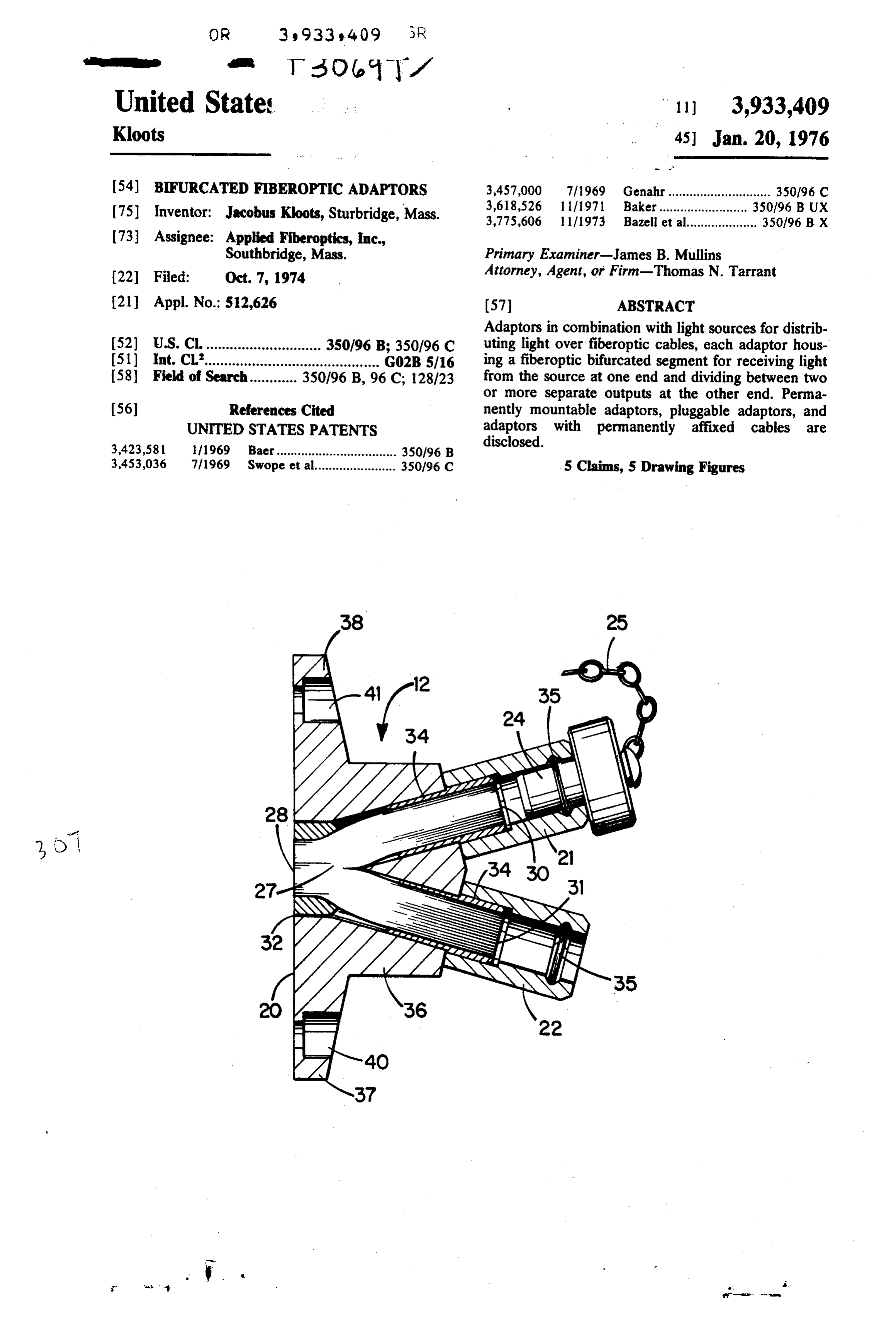
United State 11 3,933,409 Kloots 45) Jan. 20, 1976 (54) BFURCATED FIBEROPTIC ADAPTORS 3,457,000 7/1969 Genahr............................. 350/96 C (75) Inventor: Jacobus Kloots, Sturbridge, Mass. 3,618,526 1 1/1971 Baker......................... 350/96 BUX 3,775,606 1 1/1973 Bazell et al.................... 350/96 B X 73 Assignee: Applied Fiberoptics, Inc.,
Southbridge, Mass. Primary Examiner-James B. Mullins 22 Filed: Oct. 7, 1974 Attorney, Agent, or Firm-Thomas N. Tarrant (21) Appl. No.: 512,626 (57) ABSTRACT Adaptors in combination with light sources for distrib (52) U.S. C. ............................. 350/96 B; 350/96 C uting light over fiberoptic cables, each adaptor hous (51) int. Cl'............................................ G02B 5/16 ing a fiberoptic bifurcated segment for receiving light 58 Field of Search............ 350/96 B, 96 C; 128/23 from the source at one end and dividing between two or more separate outputs at the other end. Perma 56) References Cited nently mountable adaptors, pluggable adaptors, and UNITED STATES PATENTS adaptors with permanently affixed cables are 3,423,581 111969 Baer.................................. 350/96 B disclosed.
3,453,036 7/1969 Swope et al....................... 350/96 C 5 Claims, 5 Drawing Figures
Page 2
Drawing sheet — no readable text.
Page 3
Drawing sheet — no readable text.
Page 4
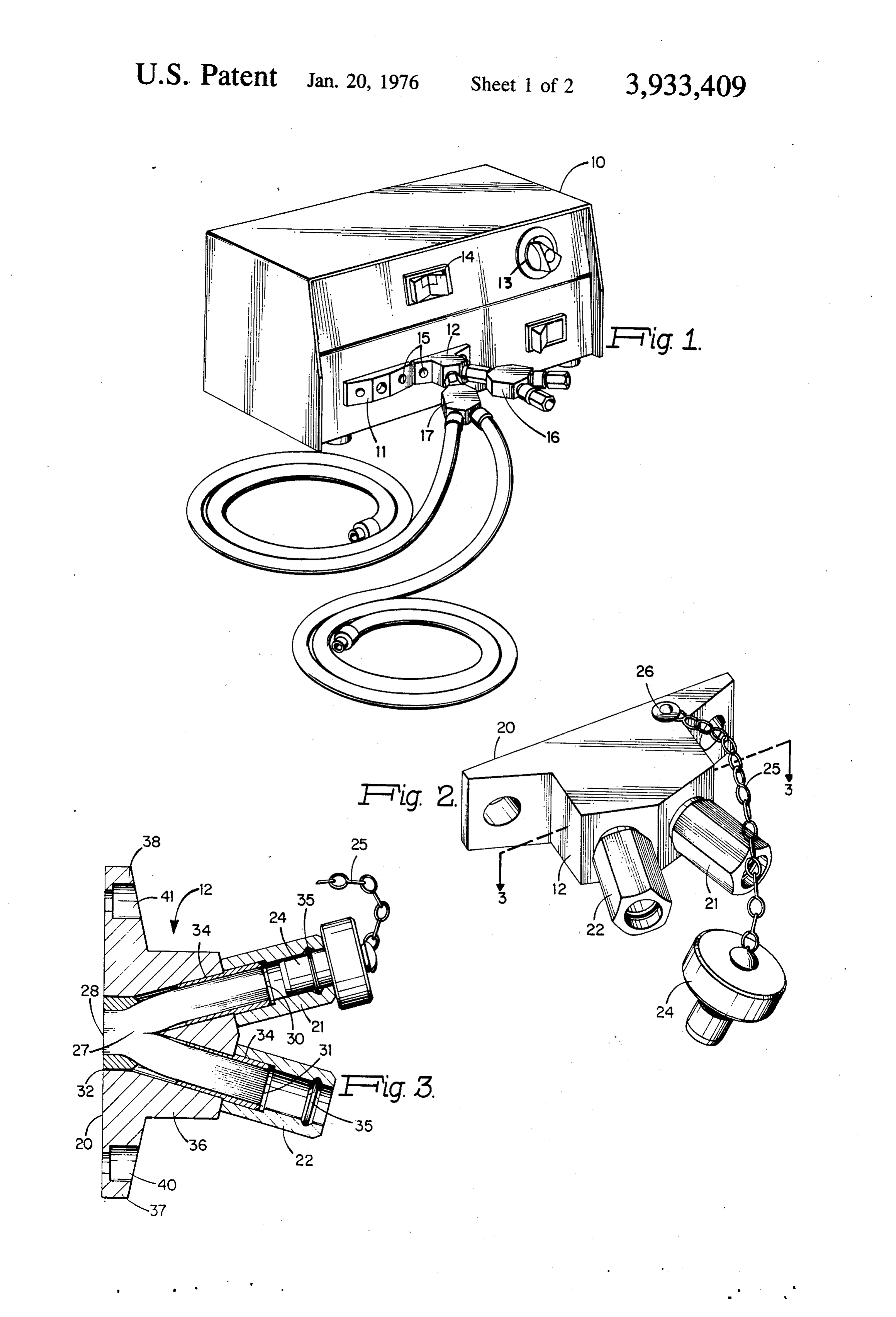
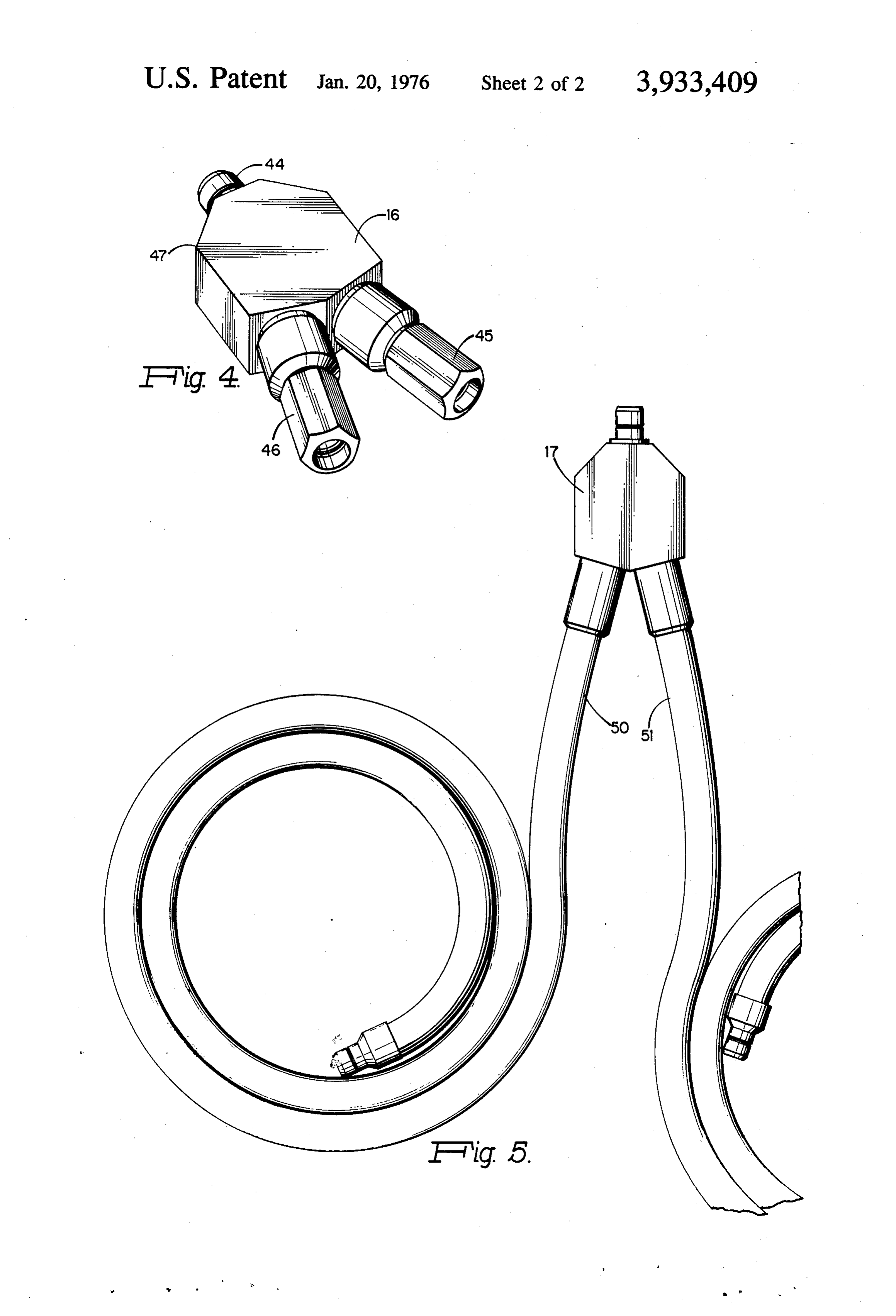
BIFURCATED FIBEROPTIC ADAPTORs FG, 4 is a plan view of a plug-in adaptor according to a second embodiment of the invention. . . '
BACKGROUND OF THE INVENTION FIG, S is a plan view of a plug-in adaptor with perma 1. Field of the Invention nently attached fiberoptic cables according to a third embodiment of the invention.
The present invention relates to apparatus for provid ing light from a source along flexible fiberoptic cables DESCRIPTION OF THE PREFERRED and particularly to such apparatus including adaptors EMBODIMENTS using bifurcated fiberoptic segments for splitting light While light sources for fiberoptics may take many from a source between a plurality of terminal illuminat 10 forms, a preferred arrangement for surgical purposes ing devices. has two nearly independent sources of light in a single 2. Description of the Prior Art unit making it possible to cover nearly all possible fail In surgical medicine today, fiberoptics has come to ures by switching the unit from one source to the other play an important role in providing illumination to previously inaccessible areas as well as better con 15 as can be done in twin source 10 of FIG. 1. Source 10 has a first light outputat socket 11 and a second light trolled illumination to previously accessible areas. An output at permanently mounted bifurcated adapter 12. example of the latter is the surgeon's headlamp. Since, Internally, source 10 has two independent light units during a surgical operation, continuous performance of selectable, by switches 14. Intensity control 13 varies all equipment is critical, light sources feeding fiberoptic the intensity, of the selected light unit or units in a con cables for medical use commonly have provision for an 20 ventional manner permitting intensity correction when immediate changeover in case of failure of a lightbulb. the light is reduced by division along several paths. Some sources have two or more lightbulbs that may be While adaptor. 12 is described as permanently switched into position by a panel switch' while others mounted, mounting is by means of screws 15 permit have two or more complete light sources within the ting change if desired. Adaptor 12 is in accordance same housing selectable by a panel switch simulta 25 with FIG. 2 while connected to one output socket of neously or in the alternative. adaptor 12 is plug-in adaptor 16 according to FIG. 4. In surgical use, it is not uncommon to require fiber Connected to the other output socket of adaptor 12 is optic illumination for two or more devices simulta adaptor 17 with permanently affixed cables as in FIG. neously. For example, in eye operations, an ophthalma scope and a surgical microscope. In abdominal surgery, 30 The units (not illustrated) inside source 10 are ar a headlamp and a retractor with integral illuminating ranged in conventional manner to focus their illumina may both be required. Either an additional light source tion on the polished ends of fiber bundles mounted to is require or a twin light source loses its insurance as the front of source 10. .. pect of an alternative source on failure... FIG. 2 depicts screw mounted bifurcated adaptor 12.
SUMMARY OF THE INVENTION At the receiving end, surface 20 is flush for mounting to the front panel of source 10. Two output connectors 21
In accordance with the present invention, light and 22 are depicted as 'separated by a 30° angle for sources for fiberoptic cables are provided with adap connection of separate fiberoptic cables. Since the unit tors whereby a single source may be divided along two of FIG. 2 is for permanent mounting, on occasion it will or more paths to provide light to a plurality of devices 40 be used with only one output device. For this purpose, and locations. These adaptors include fiberoptic cables it is desirable to block the unused output with a protec or bundles gathered to a single face at one end and tive dust cover. Thus, termination plug 24 is connected bifurcated to two faces at the other end. A variety of to adaptor 12 by small chain 25 secured by stud 26. housings for the cables or bundles are designed for FIG. 3 is a cross-sectional view of adaptor 12 showing permanent attachment to a light source, for plug-in 45 the bifurcated fiberoptic bundle. Fiberoptic bundle 27 attachment to a light source and for permanently at typically contains about 15,000 glass fibers which are tached fiberoptic cables or plug-in attached fiberoptic cemented together in a single polished receiving face cables. The adaptors in combination with a light source 28 at one end and are separated into two groups each provide a flexible multiplicity of light outputs to a plu cemented together at a polished transmitting face 30, rality of devices at remote locations. Thus, it is an ob 50 31. The number of fibers is not critical and while the ject of the invention to provide a light source for dis separation will commonly distribute substantially half tributing light over fiberoptic cables with a multiplicity the fibers to face 30 and the other half to face 31, of light output connections for distribution to a variety uneven distributions can be made where desired to of devices. It is a further object of the invention to operate devices requiring different illumination intensi provide a novel distribution system for light from a 55 ties. Cement 32 holds the receiving end of fiberoptic source through fiberoptic cables. It is still a further bundle 27 in place and cement 34 holds the transmit object of the invention to provide a novel bifurcated ting ends of fiberoptics bundle 27 in place. Snaprings fiberoptic adaptor for dividing the light output from a 35 serve to lock the plug-in ends of fiberoptic cables in source along two or morepaths. adaptor 12. Housing 36 of adaptor 12 is cast or molded Further objects and features of the invention will 60 of metal or plastic and has extending legs 37 and 38 on become apparent upon reading the following descrip each side that carry recesses 40 and 41 for mounting tion together with the Drawing. BRIEF DESCRIPTION screws 15.
OF THE DRAWING: FIG. 4 depicts adaptor 16 having plug-in jack 44 at FIG. 1 is a perspective view of light source apparatus the receiving end and two plug-in receptacles 45 and with adaptors according to the invention connected. 65 46 at the transmitting end similar to 21 and 22 of FIG. FIG. 2 is a perspective view of a one embodiment of 2. Body 47 houses a bifurcated fiberoptic bundle simi the invention. lar to fiberoptic bundle 27, but extending into jack 44 FIG. 3 is a cross section taken along 3-3 of FIG. 2. at the receiving end.
Page 5
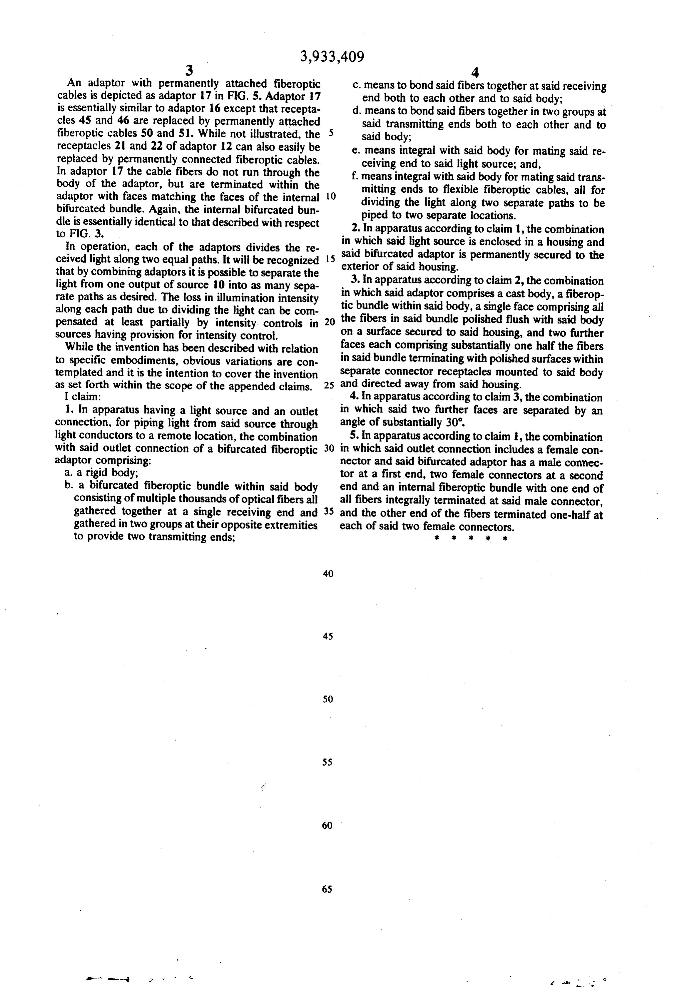
An adaptor with permanently attached fiberoptic c. means to bond said fibers together at said receiving cables is depicted as adaptor 17 in FIG. 5. Adaptor 17 end both to each other and to said body; -- - is essentially similar to adaptor 16 except that recepta d. means to bond said fibers together in two groups at cles 45 and 46 are replaced by permanently attached said transmitting ends both to each other and to fiberoptic cables 50 and 51. While not illustrated, the said body;
receptacles 21 and 22 of adaptor 12 can also easily be e. means integral with said body for mating said re replaced by permanently connected fiberoptic cables. ceiving end to said light source; and, In adaptor 17 the cable fibers do not run through the f. means integral with said body for mating said trans body of the adaptor, but are terminated within the mitting ends to flexible fiberoptic cables, all for adaptor with faces matching the faces of the internal 10 dividing the light along two separate paths to be bifurcated bundle. Again, the internal bifurcated bun piped to two separate locations. dle is essentially identical to that described with respect 2. In apparatus according to claim 1, the combination to FIG. 3.
in which said in operation, each of the adaptors divides the re said bifurcated adaptor light source is enclosed in a housing and ceived light along two equal paths. It will be recognized exterior of said housing.is permanently secured to the
that by combining adaptors it is possible to separate the light from one output of source 10 into as many sepa in 3.which In apparatus according to claim 2, the combination said adaptor comprises a cast body, a fiberop rate paths as desired. The loss in illumination intensity tic bundle within said body, a single face comprising all along each path due to dividing the light can be com pensated at least partially by intensity controls in 20 the fibers in said bundle polished flush with said body sources having provision for intensity control. on a surface secured to said housing, and two further While the invention has been described with relation faces each comprising substantially one half the fibers to specific embodiments, obvious variations are con in said bundle terminating with polished surfaces within templated and it is the intention to cover the invention separate connector receptacles mounted to said body as set forth within the scope of the appended claims. 25 and directed away from said housing. I claim: 4. In apparatus according to claim 3, the combination 1. In apparatus having a light source and an outlet in which said two further faces are separated by an connection, for piping light from said source through angle of substantially 30'.
light conductors to a remote location, the combination 5. In apparatus according to claim i, the combination with said outlet connection of a bifurcated fiberoptic 30 in which said outlet connection includes a female con adaptor comprising: nector and said bifurcated adaptor has a male connec a. a rigid body; tor at a first end, two female connectors at a second b. a bifurcated fiberoptic bundle within said body end and an internal fiberoptic bundle with one end of consisting of multiple thousands of optical fibers all all fibers integrally terminated at said male connector, gathered together at a single receiving end and 35 and the other end of the fibers terminated one-half at gathered in two groups at their opposite extremities each of said two female connectors.
to provide two transmitting ends; k k k k
Provenance
- Collection
- Cited prior art
- Original PDF
- patentimages.storage.googleapis.com →
- Filed
- 1974-10-07
- Pages
- 5
- Method
- pdftotext (the PDF's own text layer) + pdftoppm 300dpi page scans
- Source
- Google Patents bibliographic record
- Granted
- 1976-01-20
- Inventors
- Jacobus Kloots; Applied Fiber Optics Inc
- Transcribed from
- patentimages.storage.googleapis.com →