patent · US2992587
Fiber optical devices
18 July 1961
Page 1
Drawing sheet — no readable text.
Page 2
United States Patent Office Patented July 18, 1961
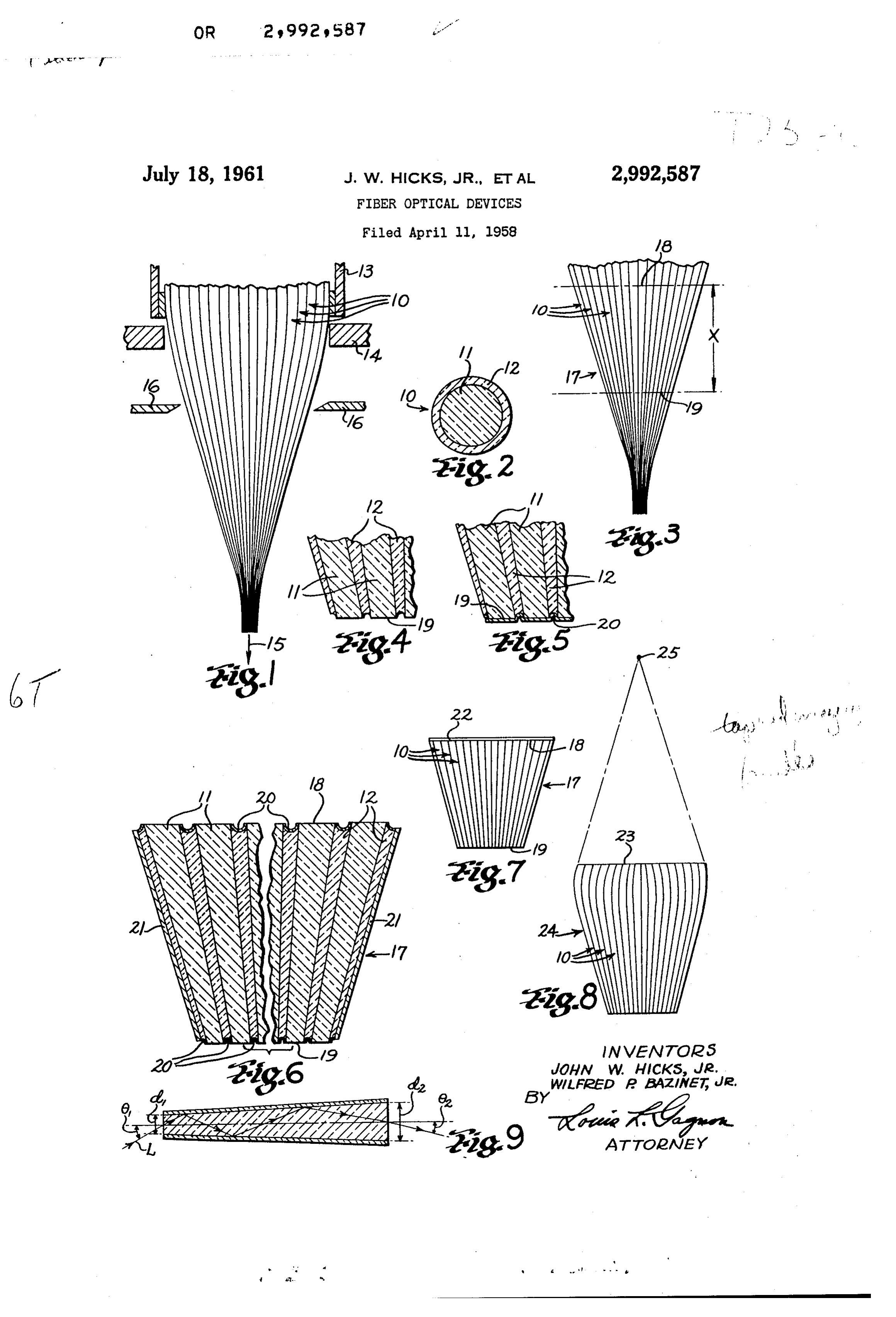
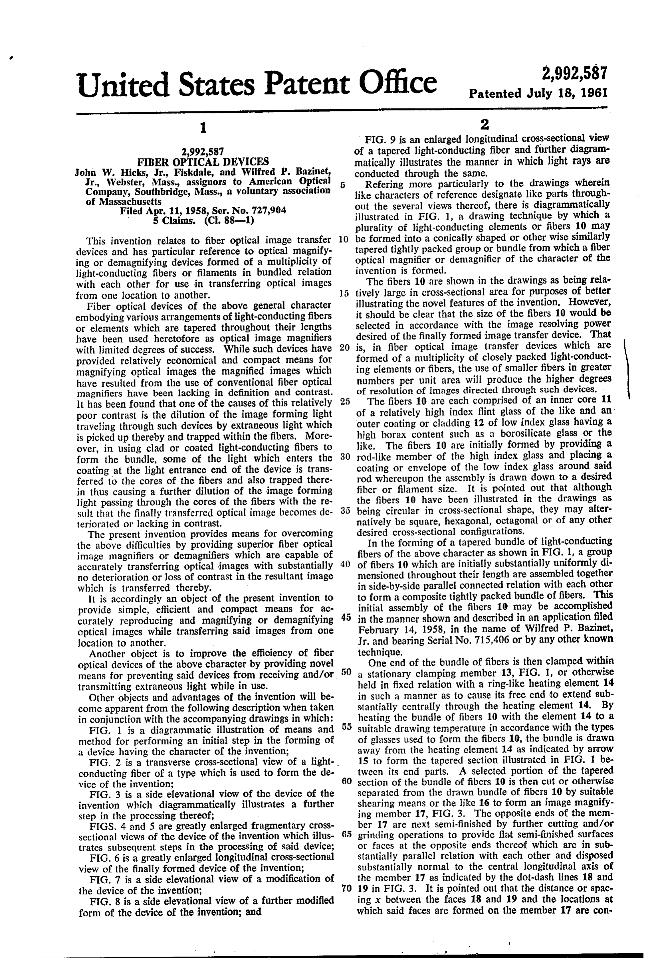
FIG. 9 is an enlarged longitudinal cross-sectional view 2,992,587 of a tapered light-conducting fiber and further diagram FBER OPTICAL DEVICES matically illustrates the manner in which light rays are John W. Hicks, Jr., Fiskdale, and Wilfred P. Bazinet, conducted through the same.
Jr., Webster, Mass, assignors to American Optical Refering more particularly to the drawings wherein Company, Southbridge, Mass., a voluntary association like characters of reference designate like parts through of Massachusetts out the several views thereof, there is diagrammatically Filed Apr. 11, 1958, Ser. No. 727,904 illustrated in FIG. 1, a drawing technique by which a 5 Claims. (C. 88-1) plurality of light-conducting elements or fibers 10 may be formed into a conically shaped or other wise similarly
This invention relates to fiber optical image transfer 10 tapered devices and has particular reference to optical magnify optical magnifier tightly packed group or bundle from which a fiber ing or demagnifying devices formed of a multiplicity of or demagnifier of the character of the light-conducting fibers or filaments in bundled relation invention is formed.
with each other for use in transferring optical images The fibers 10 are shown in the drawings as being rela from one location to another. 5 tively large in cross-sectional area for purposes of better Fiber optical devices of the above general character illustrating the novel features of the invention. However, embodying various arrangements of light-conducting fibers it should be clear that the size of the fibers 10 would be or elements which are tapered throughout their lengths selected in accordance with the image resolving power have been used heretofore as optical image magnifiers desired of the finally formed image transfer device. That with limited degrees of success, While such devices have 20 is, in fiber optical image transfer devices which are formed of a multiplicity of closely packed light-conduct provided relatively economical and compact means for magnifying optical images the magnified images which ing elements or fibers, the use of smaller fibers in greater have resulted from the use of conventional fiber optical numbers per unit area will produce the higher degrees magnifiers have been lacking in definition and contrast. of resolution of images directed through such devices. It has been found that one of the causes of this relatively 25 The fibers 10 are each comprised of an inner core 11 poor contrast is the dilution of the image forming light of a relatively high index flint glass of the like and an traveling through such devices by extraneous light which outer coating or cladding 12 of low index glass having a is picked up thereby and trapped within the fibers. More high borax content such as a borosilicate glass or the over, in using clad or coated light-conducting fibers to 30 like. The fibers 10 are initially formed by providing a form the bundle, some of the light which enters the rod-like member of the high index glass and placing a coating at the light entrance end of the device is trans coating or envelope of the low index glass around said ferred to the cores of the fibers and also trapped there rod whereupon the assembly is drawn down to a desired in thus causing a further dilution of the image forming fiber or filament size. It is pointed out that although light passing through the cores of the fibers with the re the fibers 10 have been illustrated in the drawings as sult that the finally transferred optical image becomes de being circular in cross-sectional shape, they may alter teriorated or lacking in contrast. natively be square, hexagonal, octagonal or of any other The present invention provides means for overcoming desired cross-sectional configurations. the above difficulties by providing superior fiber optical In the forming of a tapered bundle of light-conducting image magnifiers or demagnifiers which are capable of fibers of the above character as shown in FIG. 1, a group accurately transferring optical images with substantially 40 of fibers 10 which are initially substantially uniformly di no deterioration or loss of contrast in the resultant image mensioned throughout their length are assembled together which is transferred thereby. in side-by-side parallel connected relation with each other It is accordingly an object of the present invention to to form a composite tightly packed bundle of fibers. This provide simple, efficient and compact means for ac initial assembly of the fibers 10 may be accomplished curately reproducing and magnifying or demagnifying in the manner shown and described in an application filed optical images while transferring said images from one February 14, 1958, in the name of Wilfred P. Bazinet, location to another. Jr. and bearing Serial No. 715,406 or by any other known Another object is to improve the efficiency of fiber technique.
optical devices of the above character by providing novel 50 One end of the bundle of fibers is then clamped within means for preventing said devices from receiving and/or a stationary clamping member 13, FIG. 1, or otherwise transmitting extraneous light while in use. held in fixed relation with a ring-like heating element 14 Other objects and advantages of the invention will be in such a manner as to cause its free end to extend sub come apparent from the following description when taken stantially centrally through the heating element 14. By in conjunction with the accompanying drawings in which: heating the bundle of fibers 10 with the element 14 to a FIG. 1 is a diagrammatic illustration of means and suitable drawing temperature in accordance with the types method for performing an initial step in the forming of of glasses used to form the fibers 10, the bundle is drawn a device having the character of the invention; away from the heating element 14 as indicated by arrow FIG. 2 is a transverse cross-sectional view of a light 15 to form the tapered section illustrated in FIG. 1 be conducting fiber of a type which is used to form the de 60 tween its end parts. A selected portion of the tapered vice of the invention; section of the bundle of fibers 10 is then cut or otherwise FIG. 3 is a side elevational view of the device of the separated from the drawn bundle of fibers 10 by suitable invention which diagrammatically illustrates a further shearing means or the like 16 to form an image magnify step in the processing thereof; ing member 17, FIG. 3. The opposite ends of the mem FIGS. 4 and 5 are greatly enlarged fragmentary cross 65 ber 17 are next semi-finished by further cutting and/or sectional views of the device of the invention which illus grinding operations to provide flat semi-finished surfaces trates subsequent steps in the processing of said device; or faces at the opposite ends thereof which are in sub FIG. 6 is a greatly enlarged longitudinal cross-sectional stantially parallel relation with each other and disposed view of the finally formed device of the invention; Substantially normal to the central longitudinal axis of FIG. 7 is a side elevational view of a modification of the member 17 as indicated by the dot-dash lines 18 and the device of the invention; 70 19 in FIG, 3. It is pointed out that the distance or spac FIG, 8 is a side elevational view of a further modified ing x between the faces 18 and 19 and the locations at form of the device of the invention; and which said faces are formed on the member 17 are con
Page 3
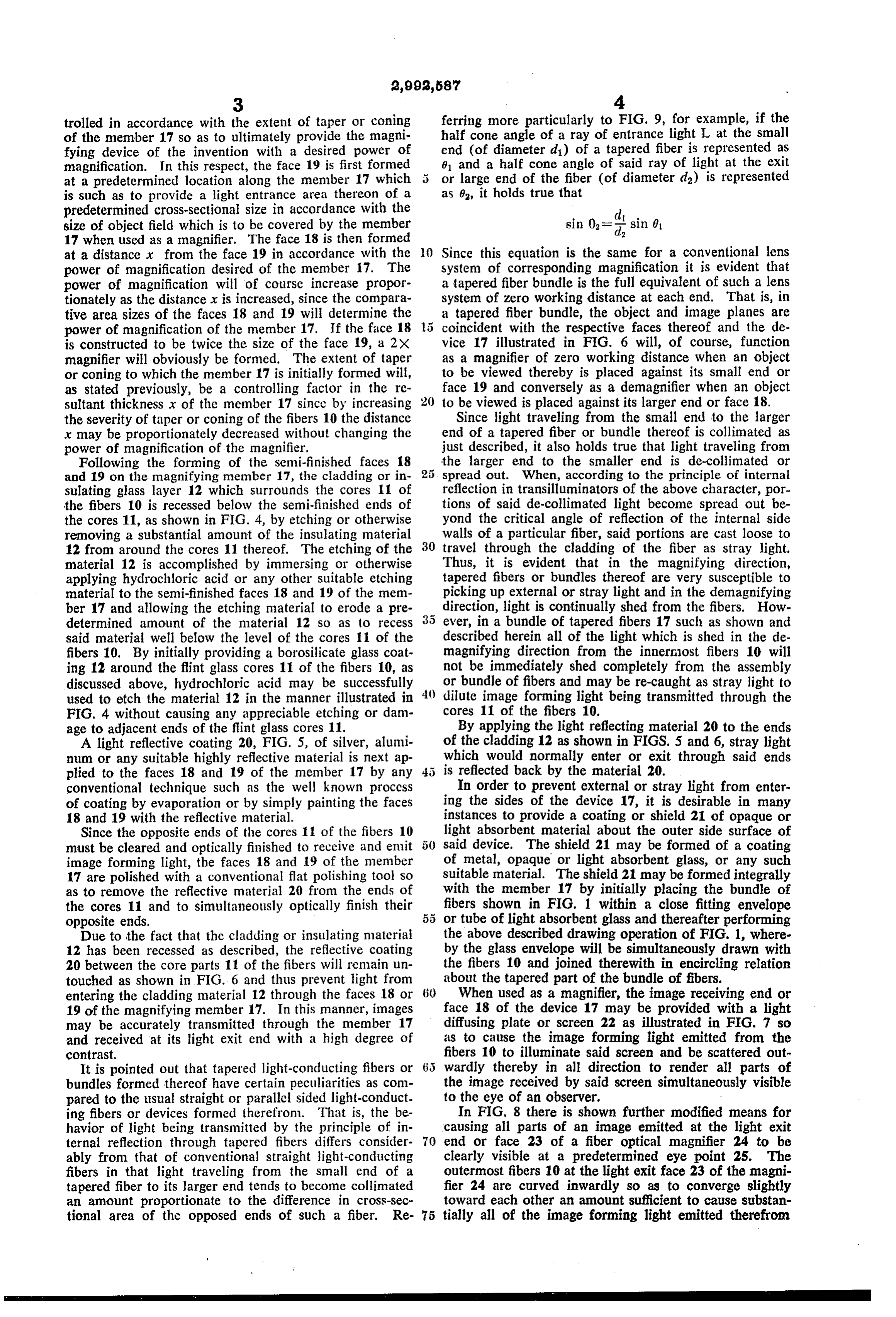
trolled in accordance with the extent of taper or coning ferring more particularly to FIG. 9, for example, if the of the member 17 so as to ultimately provide the magni half cone angle of a ray of entrance light L at the small fying device of the invention with a desired power of end (of diameter di) of a tapered fiber is represented as magnification. In this respect, the face 19 is first formed 01 and a half cone angle of said ray of light at the exit at a predetermined location along the member 17 which 5 or large end of the fiber (of diameter da) is represented is such as to provide a light entrance area thereon of a as 0, it holds true that predetermined cross-sectional size in accordance with the size of object field which is to be covered by the member sin 0 = sin 0. 17 when used as a magnifier. The face 18 is then formed at a distance r from the face 19 in accordance with the 10 Since this equation is the same for a conventional lens power of magnification desired of the member 17. The system of corresponding magnification it is evident that power of magnification will of course increase propor a tapered fiber bundle is the full equivalent of such a lens tionately as the distance r is increased, since the compara system of zero working distance at each end. That is, in tive area sizes of the faces 18 and 19 will determine the a tapered fiber bundle, the object and image planes are power of magnification of the member 17. If the face 18 coincident with the respective faces thereof and the de is constructed to be twice the size of the face 19, a 2X vice 17 illustrated in FIG. 6 will, of course, function magnifier will obviously be formed. The extent of taper as a magnifier of zero working distance when an object or coning to which the member 17 is initially formed will, to be viewed thereby is placed against its small end or as stated previously, be a controlling factor in the re face 19 and conversely as a demagnifier when an object sultant thickness x of the member 17 since by increasing 20 to be viewed is placed against its larger end or face 18. the severity of taper or coning of the fibers 10 the distance Since light traveling from the small end to the larger x may be proportionately decreased without changing the end of a tapered fiber or bundle thereof is collimated as power of magnification of the magnifier. just described, it also holds true that light traveling from Following the forming of the semi-finished faces 18 the larger end to the smaller end is de-collimated or and 19 on the magnifying member 17, the cladding or in spread out. When, according to the principle of internal sulating glass layer 12 which surrounds the cores 11 of reflection in transilluminators of the above character, por the fibers 10 is recessed below the semi-finished ends of tions of said de-collimated light become spread out be the cores 11, as shown in FIG. 4, by etching or otherwise yond the critical angle of reflection of the internal side removing a substantial amount of the insulating material walls of a particular fiber, said portions are cast loose to 12 from around the cores 11 thereof. The etching of the 30 travel through the cladding of the fiber as stray light. material 12 is accomplished by immersing or otherwise Thus, it is evident that in the magnifying direction, applying hydrochloric acid or any other suitable etching tapered fibers or bundles thereof are very susceptible to material to the semi-finished faces 18 and 19 of the mem picking up external or stray light and in the demagnifying ber 17 and allowing the etching material to erode a pre direction, light is continually shed from the fibers. How determined amount of the material 12 so as to recess ever, in a bundle of tapered fibers 17 such as shown and said material well below the level of the cores 11 of the described herein all of the light which is shed in the de fibers 10. By initially providing a borosilicate glass coat magnifying direction from the innermost fibers 10 will ing 12 around the flint glass cores 11 of the fibers 10, as not be immediately shed completely from the assembly discussed above, hydrochloric acid may be successfully or bundle of fibers and may be re-caught as stray light to used to etch the material 12 in the manner illustrated in dilute image forming light being transmitted through the FIG. 4 without causing any appreciable etching or dam cores 11 of the fibers 10.
age to adjacent ends of the flint glass cores 11. By applying the light reflecting material 20 to the ends A light reflective coating 20, FIG. 5, of silver, alumi of the cladding 12 as shown in FIGS. 5 and 6, stray light num or any suitable highly reflective material is next ap which would normally enter or exit through said ends plied to the faces 18 and 19 of the member 17 by any is reflected back by the material 20. conventional technique such as the well known process In order to prevent external or stray light from enter of coating by evaporation or by simply painting the faces ing the sides of the device 17, it is desirable in many 18 and 19 with the reflective material. instances to provide a coating or shield 21 of opaque or Since the opposite ends of the cores 11 of the fibers 10 light absorbent material about the outer side surface of must be cleared and optically finished to receive and emit said device. The shield 21 may be formed of a coating image forming light, the faces 18 and 19 of the member of metal, opaque or light absorbent glass, or any such 17 are polished with a conventional flat polishing tool so suitable material. The shield 21 may be formed integrally as to remove the reflective material 20 from the ends of with the member 17 by initially placing the bundle of the cores 11 and to simultaneously optically finish their fibers shown in FIG. 1 within a close fitting envelope opposite ends. or tube of light absorbent glass and thereafter performing Due to the fact that the cladding or insulating material the above described drawing operation of FIG. 1, where 12 has been recessed as described, the reflective coating by the glass envelope will be simultaneously drawn with 20 between the core parts 11 of the fibers will remain un the fibers 10 and joined therewith in encircling relation touched as shown in FIG. 6 and thus prevent light from about the tapered part of the bundle of fibers. entering the cladding material 12 through the faces 18 or 6) When used as a magnifier, the image receiving end or 19 of the magnifying member 17. In this manner, images face 18 of the device 17 may be provided with a light may be accurately transmitted through the member 17 diffusing plate or screen 22 as illustrated in FIG. 7 so and received at its light exit end with a high degree of as to cause the image forming light emitted from the contrast, fibers 10 to illuminate said screen and be scattered out It is pointed out that tapered light-conducting fibers or wardly thereby in all direction to render all parts of bundles formed thereof have certain peculiarities as com the image received by said screen simultaneously visible pared to the usual straight or parallel sided light-conduct to the eye of an observer.
ing fibers or devices formed therefrom. That is, the be In FIG. 8 there is shown further modified means for havior of light being transmitted by the principle of in causing all parts of an image emitted at the light exit ternal reflection through tapered fibers differs consider end or face 23 of a fiber optical magnifier 24 to be ably from that of conventional straight light-conducting clearly visible at a predetermined eye point 25. The fibers in that light traveling from the small end of a outermost fibers 10 at the light exit face 23 of the magni tapered fiber to its larger end tends to become collimated fier 24 are curved inwardly so as to converge slightly an amount proportionate to the difference in cross-sec toward each other an amount sufficient to cause substan tional area of the opposed ends of such a fiber. Re- 75 tially all of the image forming light emitted therefrom
Page 4
to be directed toward the predetermined viewing location said bundle to prevent light from entering said fibers through the sides thereof.
or eye point 25. 2. A fiber optical device comprising a multiplicity of The magnifier 24 is constructed in a manner similar tapered light-conducting fibers each embodying a core to the magnifier 17 with the exception that the convergent part end or face 23 is initially formed by reversing a bundle 5 indexofoflight-conducting material having a relatively high refraction and a surrounding coating of trans of fibers 10 such as illustrated in FIG. 1 following the parent material drawing operation described hereinabove and securing tion, said fibers having a relatively low index of refrac being in intimate side-by-side connected the tapered part thereof in the clamp 13 whereupon the relation with each other and having their central longi bundle is reheated and drawn from its opposite end an tudinal axes in divergent relation with each other to amount sufficient to produce a slight taper or coning 10 form a composite tapered bundle of said fibers, each of at its light exit end 23. The device 24 is then cut from the opposite ends of said core parts of the fibers being the drawn bundle at predetermined locations above and optically finished in planes disposed substantially normal below its widest part to form its light entrance and exit to a central longitudinal axis through said bundle, said faces. transparent coatings being recessed at their opposite ends It should be understood that since fiber optical devices below the respective adjacent ends of said core parts, a of the above character have zero working distances, the layer of light reflecting means connected to and covering light entrance and exit ends or faces thereof may be said recessed ends of said coatings whereby light will be formed to any desired shape other than the flat surfaces permitted illustrated in the drawings. That is, the objective or image 20 parts of theto fibers enter and exit from the ends of said core but will be prevented from entering or receiving end of the device 17 may be shaped to corre spond to the shape of the plane of the image which is exiting through said recessed ends of said transparent to be projected through the device 17 whether said image coatings. 3. A fiber optical device comprising a multiplicity of plane is flat, concavely or convexly curved or otherwise contoured. Moreover, the light exit end of the device tapered light-conducting fibers each embodying a core 17 may be contoured to any desired shape in accordance index of refraction and material part of light-conducting having a relatively high with the shape desired of the surface in which the trans parent material having a relatively low coating a surrounding of trans index of refrac ferred image is to be received.
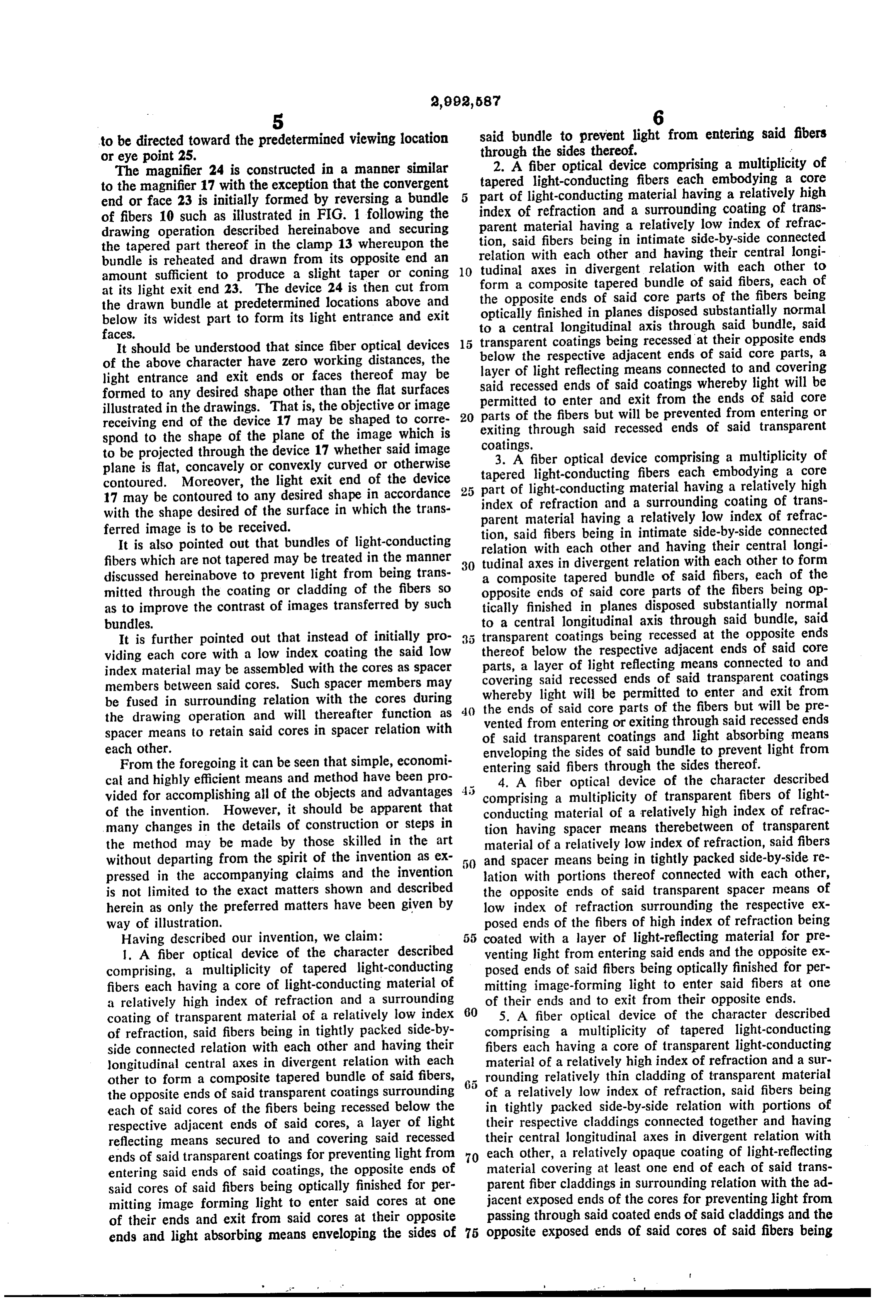
It is also pointed out that bundles of light-conducting tion, said fibers being in intimate side-by-side connected relation with each other and having their central longi fibers which are not tapered may be treated in the manner tudinal axes in divergent relation with each other to form discussed hereinabove to prevent light from being trans 30 a composite tapered bundle of said fibers, each of the mitted through the coating or cladding of the fibers so opposite ends of said core parts of the fibers being op as to improve the contrast of images transferred by such tically finished in planes disposed substantially normal bundles. to a central longitudinal axis through said bundle, said It is further pointed out that instead of initially pro 5 transparent coatings being recessed at the opposite ends viding each core with a low index coating the said low thereof below the respective adjacent ends of said core index material may be assembled with the cores as spacer parts, a layer of light reflecting means connected to and members between said cores. Such spacer members may covering said recessed ends of said transparent coatings whereby light will be permitted to enter and exit from be fused in surrounding relation with the cores during the ends of said core parts of the fibers but will be pre the drawing operation and will thereafter function as vented from entering or exiting through said recessed ends spacer means to retain said cores in spacer relation with of said transparent coatings and light absorbing means each other. enveloping the sides of said bundle to prevent light from From the foregoing it can be seen that simple, economi entering said fibers through the sides thereof. cal and highly efficient means and method have been pro 4. A fiber optical device of the character described vided for accomplishing all of the objects and advantages 4: comprising a multiplicity of transparent fibers of light of the invention. However, it should be apparent that conducting material of a relatively high index of refrac many changes in the details of construction or steps in tion having spacer means therebetween of transparent the method may be made by those skilled in the art material of a relatively low index of refraction, said fibers without departing from the spirit of the invention as ex 5() and spacer means being in tightly packed side-by-side re pressed in the accompanying claims and the invention lation with portions thereof connected with each other, is not limited to the exact matters shown and described the opposite ends of said transparent spacer means of herein as only the preferred matters have been given by low index of refraction surrounding the respective ex way of illustration. posed ends of the fibers of high index of refraction being Having described our invention, we claim: 55 coated with a layer of light-reflecting material for pre 1. A fiber optical device of the character described venting light from entering said ends and the opposite ex comprising, a multiplicity of tapered light-conducting posed ends of said fibers being optically finished for per fibers each having a core of light-conducting material of mitting image-forming light to enter said fibers at one a relatively high index of refraction and a surrounding of their ends and to exit from their opposite ends. coating of transparent material of a relatively low index 60 5. A fiber optical device of the character described of refraction, said fibers being in tightly packed side-by comprising a multiplicity of tapered light-conducting side connected relation with each other and having their fibers each having a core of transparent light-conducting longitudinal central axes in divergent relation with each material of a relatively high index of refraction and a sur other to form a composite tapered bundle of said fibers, 65 rounding relatively thin cladding of transparent material the opposite ends of said transparent coatings surrounding of a relatively low index of refraction, said fibers being each of said cores of the fibers being recessed below the in tightly packed side-by-side relation with portions of respective adjacent ends of said cores, a layer of light their respective claddings connected together and having reflecting means secured to and covering said recessed their central longitudinal axes in divergent relation with ends of said transparent coatings for preventing light from 70 each other, a relatively opaque coating of light-reflecting entering said ends of said coatings, the opposite ends of material covering at least one end of each of said trans said cores of said fibers being optically finished for per parent fiber claddings in surrounding relation with the ad mitting image forming light to enter said cores at one jacent exposed ends of the cores for preventing light from of their ends and exit from said cores at their opposite passing through said coated ends of said claddings and the ends and light absorbing means enveloping the sides of 75 opposite exposed ends of said cores of said fibers being
Page 5
optically finished for permitting light to enter said cores 2,328,302 Simison --------------- Aug. 31, 1943 at one of their ends and to exit from their opposite ends. 2,510,106 Henroteau -------------- June 6, 1950 References Cited in the file of this patent 2,825,260 O'Brien -------------- Mar. 4, 1958 UNITED STATES PATENTS 5 2,877,368 Sheldon -------------- Mar. 10, 1959
Provenance
- Collection
- Cited prior art
- Original PDF
- patentimages.storage.googleapis.com →
- Filed
- 1958-04-11
- Pages
- 5
- Method
- pdftotext (the PDF's own text layer) + pdftoppm 300dpi page scans
- Source
- Google Patents bibliographic record
- Granted
- 1961-07-18
- Inventors
- Jr John W Hicks; Jr Wilfred P Bazinet; American Optical Corp
- Transcribed from
- patentimages.storage.googleapis.com →