patent · US3814081
Optical measuring catheter
4 June 1974
Page 1 — bibliographic record
United Stat A. (11) 3,814,081
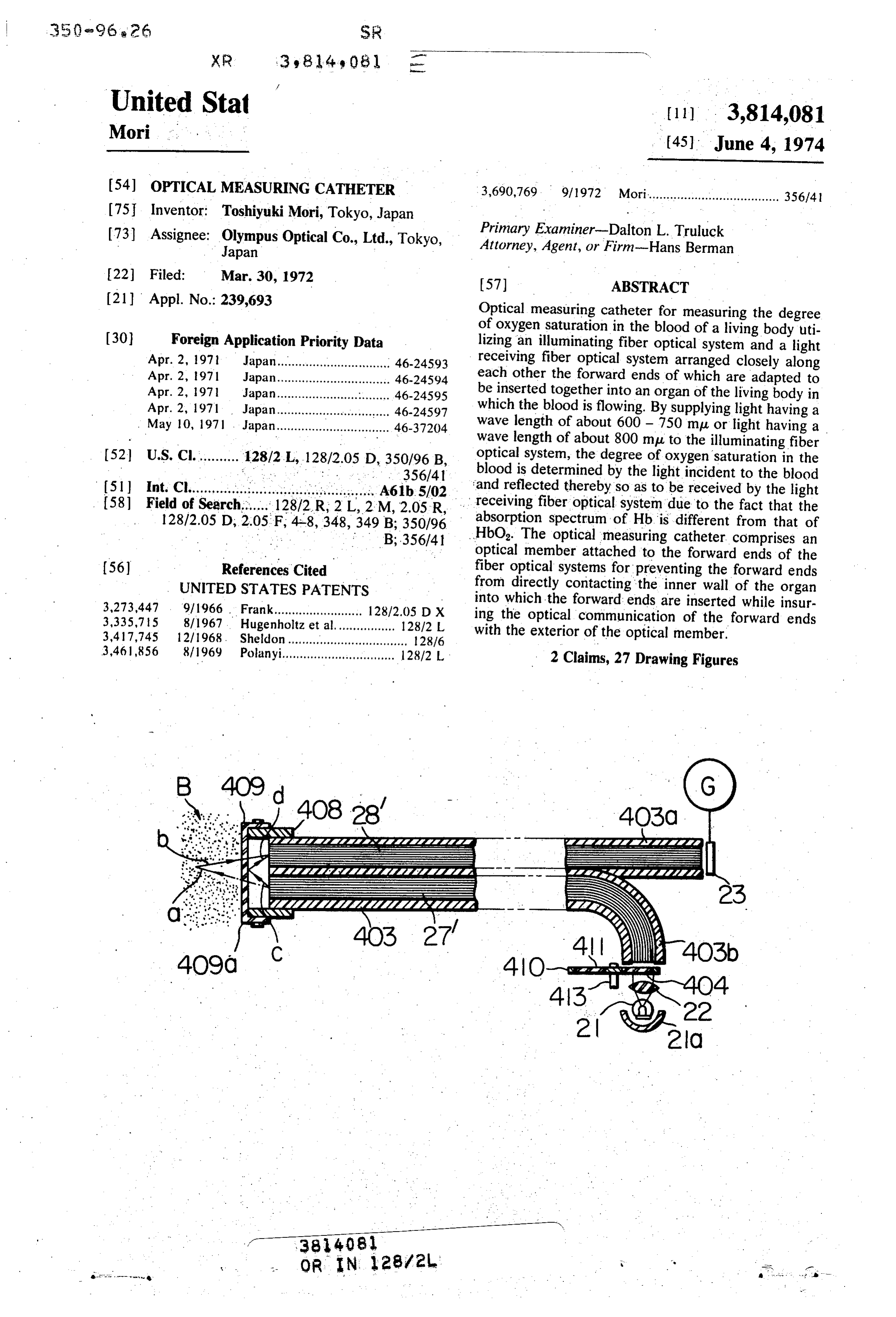
54) OPTICAL MEASURING CATHETER 3,690,769 9/1972 Mori................. . . . . . . . . . . . . . . . . . . . . 356/4 75 Inventor: Toshiyuki Mori, Tokyo, Japan (73) Assignee: Olympus Optical Co., Ltd., Tokyo, Primary Examiner-Dalton L. Truluck Japan - Attorney, Agent, or Firm-Hans Berman 22 Filed: Mar. 30, 1972 (57) ABSTRACT (21) Appl. No.: 239,693 Optical measuring catheter for measuring the degree of oxygen saturation in the blood of a living body uti (30) Foreign Application Priority Data lizing an illuminating fiber optical system and a light Apr. 2, 1971 Japan................................ 46-24593 receiving fiber optical system arranged closely along Apr. 2, 1971 Japan................................ 46-24594 each other the forward ends of which are adapted to Apr. 2, 1971 Japan............................... 46-24595 be inserted together into an organ of the living body in Apr. 2, 1971 Japan............... ... 46-24597 which the blood is flowing. By supplying light having a May 10, 1971 . Japan..............r 46-37204 wave length of about 600 - 750 mpu or light having a wave length of about 800 mpu to the illuminating fiber 52 U.S. Cl........... 128/2 L, 128/2.05 D, 350/96 B, optical system, the degree of oxygensaturation in the * . . . . . . . . .356/41 blood is determined by the light incident to the blood 5l Int. Ct...............i............................... A61b.5/02 and reflected thereby so as to be received by the light 581 Field of Search...... 128/2R, 2 L, 2 M, 2.05 R, receiving fiber optical system due to the fact that the
350/96 absorption spectrum of Hb is different from that of
HbO. The optical measuring catheter comprises an optical member attached to the forward ends of the (56) References Cited fiber optical systems for preventing the forward ends UNITED STATES PATENTS from directly contacting the inner wall of the organ 3,273,447 9/1966. Frank......................... 128/2.05 DX into which the forward ends are inserted while insur 3,335,75 8/1967. Hugenholtz et al................. 128/2 L ing the optical communication of the forward ends 34 17,745 12/1968. Sheldon......... ........................ 128/6 with the exterior of the optical member. 3,461,856 8/1969 Polanyi.................... . . . . . . ... 128/2 L 2 Claims, 27 Drawing Figures
ester
PRP
– ecceee
38.408 s
Page 2
Drawing sheet — no readable text.
Page 3
Drawing sheet — no readable text.
Page 4
Drawing sheet — no readable text.
Page 5
Drawing sheet — no readable text.
Page 6
Drawing sheet — no readable text.
Page 7
OPTICAL MEASURING CATHETER The present invention aims at providing an optical measuring catheter which avoids the above described
BACKGROUND OF THE INVENTION disadvantages of the prior art.
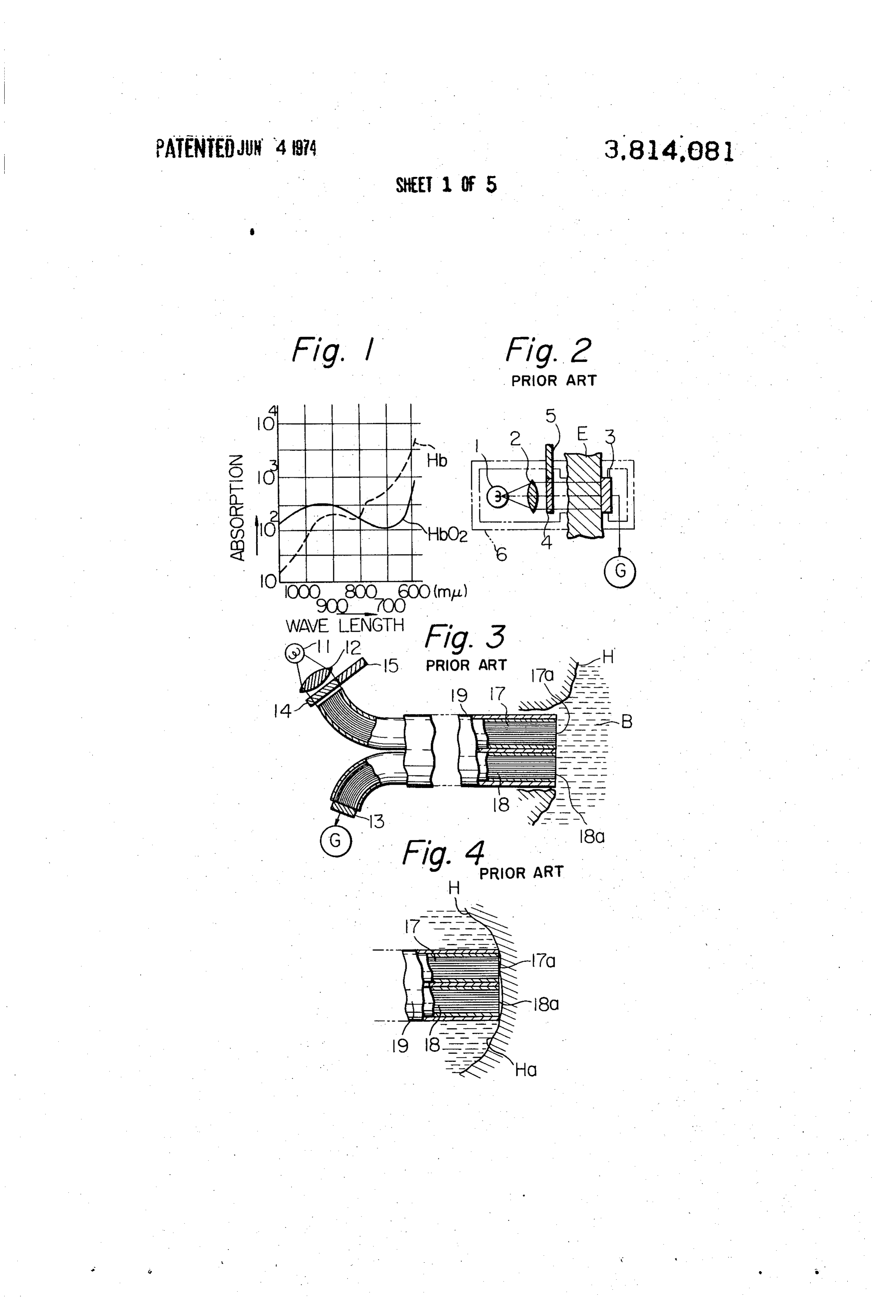
The present invention relates to an optical measuring A further object is to provide a novel and useful opti catheter and, more particularly, to an optical measur cal measuring catheter by which the blood pressure of ing catheter for measuring the degree of oxygen satura a living body as well as the variation in the blood pres tion in the blood of a living body and the blood pressure sure can be measured together with the degree of oxy as well as the variation thereof. gen saturation in the blood. The degree of oxygen saturation in the blood is mea O BRIEF DESCRIPTION OF THE DRAWINGS sured in order to find out the degree of conversion of reduced hemoglobin (Hb) into oxidized hemoglobin ofFIG. the 1 is a diagram showing the absorption spectrum oxidized and the reduced hemoglobin;
(HbO2) by the lungs of a living body. In the conven FIG. 2 is a schematic view partly in section showing tional cuvette system blood is taken out from the living the prior art earpiece system;
body for the direct measurement of the degree of oxy 15 gen. High skill is required for the measurement while theFIG. 3 is a schematic view partly in section showing prior art method for measuring the saturation de a long time is required until the result is obtained, al gree of oxygen in the blood by using fiber optical sys though the result is accurate, and the living body might tems, .
be harmed when the blood is taken out for the mea
Surennent. FIG. 4 is a fragmentary view showing the forward ends of the fiber optical system of FIG. 3 abutting
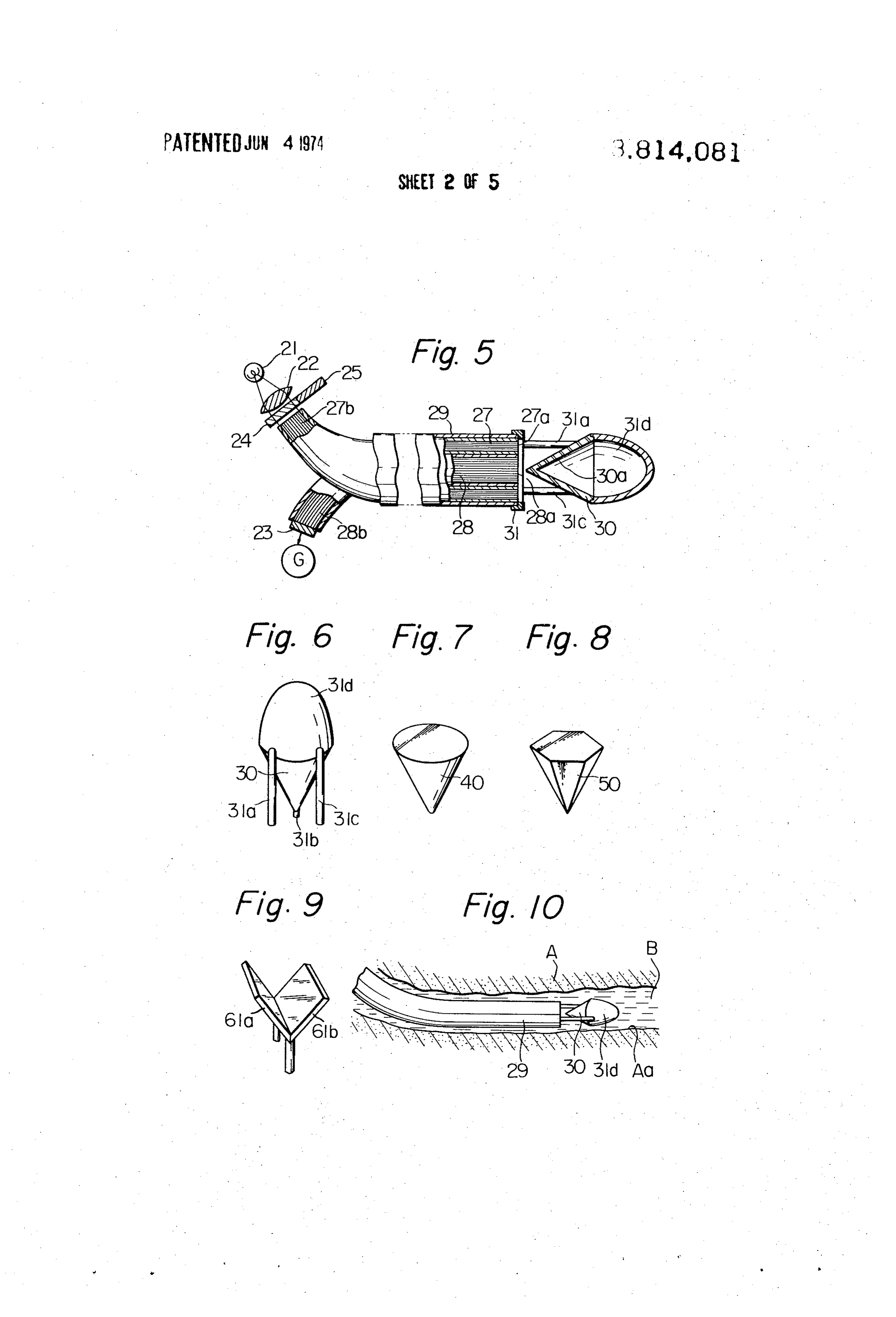
In order to avoid the above disadvantages, another against the wall of the heart method has been proposed which is called the ear FIG. 5 is a schematic view partly in section showing piece system in which the measuring device is attached a first to the ear lobe of the living body, and the light passing ing theembodiment of the present invention for measur through the blood flowing in the lobe is determined. 25 FIG. 6 is a fragmentarysaturation degree of oxygen in the blood;
perspective view showing a
However, compensation for the thickness of the lobe, cone-shaped reflecting mirror incorporated in the em the quantity of the blood flowing in the lobe, and the bodiment of FIG. 5;
color of the skin of the lobe is required thereby making FIGS. 7 to 9 are perspective views of respective mod the measurement very troublesome.
A further method has been proposed to avoid the 30 FIG. 10ofis the ifications
reflecting mirror of FIG. 6;
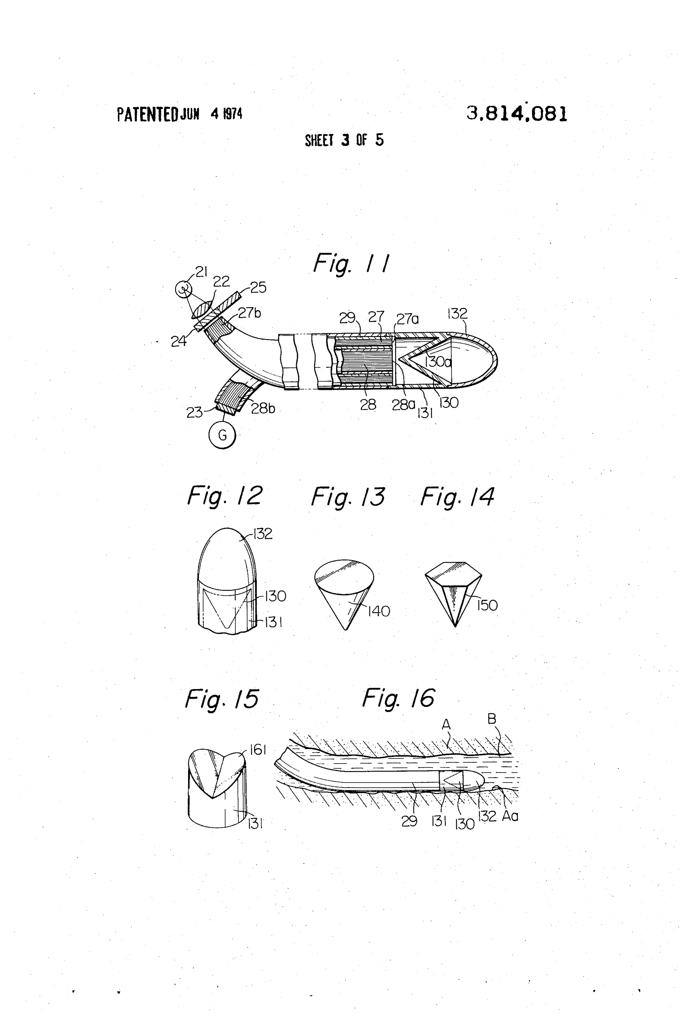
fragmentary side view showing the for above described difficulties. This method utilizes an il ward end portion of the embodiment of FIG. 5 inserted luminating fiber optical system and a light receiving in a blood vessel of a living body; . ., fiber optical system arranged closely in parallel to each FIG. 11 is a view similar to FIG. 5 but showing a mod other with the forward ends being flush with each ification of the embodiment of FIG. 5;
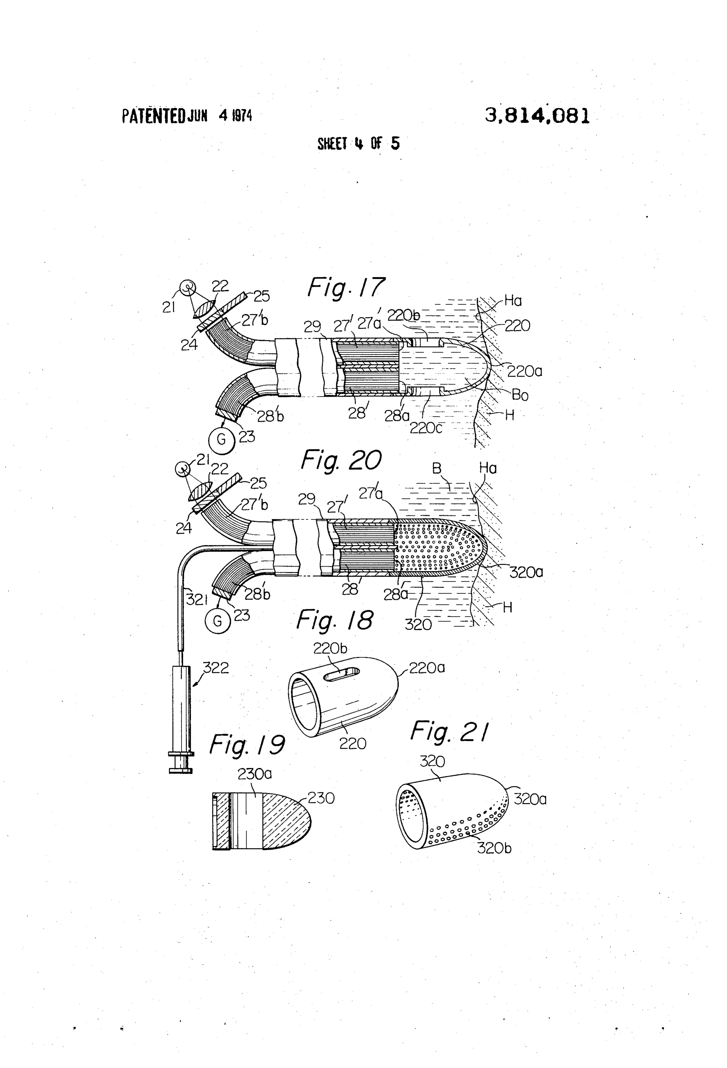
other. The forward end portions are inserted into a 35 FIG. 12 is a fragmentary perspective view showing blood vessel or into the heart of the living body. A light the cone-shaped reflecting mirror incorporated in the source and a condenser lens are arranged at the rear embodiment of FIG. 11; * , end of the illuminating fiber optical system so as to sup FIGS. 13 to 15 are fragmentary perspective views ply the light thereto, while a photoelectric element is each showing a modification of the reflecting mirror of attached to the rear end of the light receiving fiber opti 40 FIG. 12; "... cal system and a galvanometer is connected to the pho FIG. 16 is a fragmentary side view showing the for toelectric element, so that the light emanating from the ward end portion of the embodiment forward end of the illuminating fiber optical system is serted in a blood vessel of a living body;of FIG. 11 in reflected by the blood and received by the light receiv FIG. 17 is a schematic view partly in section showing ing fiber optical system so as to generate an output in 45 a further modification of the embodiment of FIG. 5; the photoelectric element to actuate the galvanometer. FIG. 18 is a perspective view showing the cup-shaped An R type filter passing only light having wave lengths blood transmitting member attached to the forward of about 600 - 750 mpu and an IR type filter passing only light having a wave length of about 800 mpu are al 50 endFIG.
of the embodiment of FIG. 17;
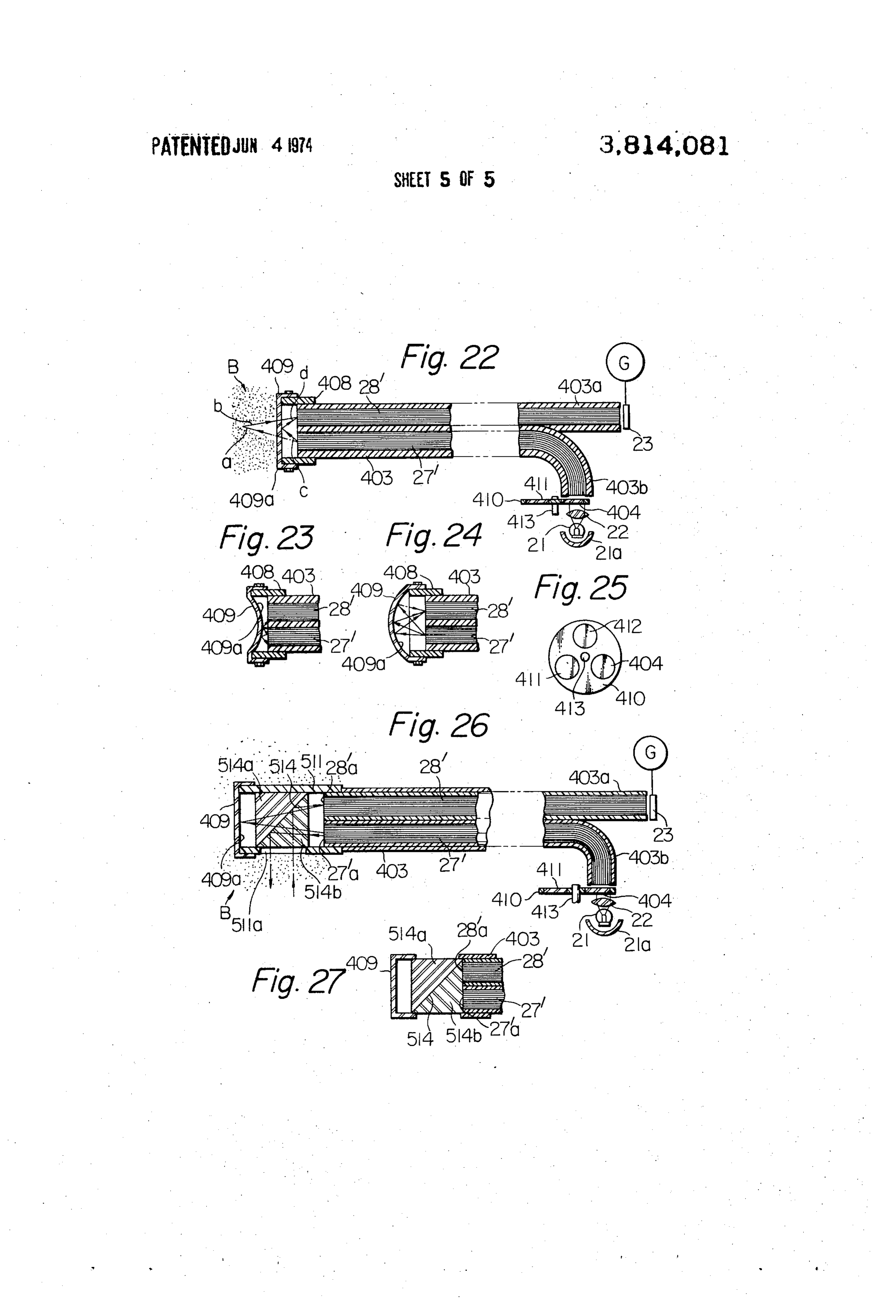
19 is a sectional view showing a modification of ternately inserted into the light path of the illuminating the cup-shaped blood transmitting member of FIG. 18; fiber optical system. Since the absorption of light hav ing wave lengths of 600-750 mpu by Hb is higher than FIG.20 is a schematic view partly in section showing the absorption by HbO, while the absorption of light a modification of the embodiment of FIG. 17; having the a wave length of 800 mp by Hb is substan 55 FIG.21 is a perspective view showing the cup-shaped tially equal to that by HbO, the output of the photoe blood transmitting member attached to the forward lectric element, when the R type filter is used, indicates the quantity of Hb, while the output of the photoelec end of the embodiment of FIG. 20; FIG. 22 is a longitudinal sectional view showing a tric element indicates the combined amount of Hb and second embodiment of the present invention by which HbO, when the IR type filter is used.
This method has the disadvantage that the forward the 60 the degree of oxygen saturation in the blood as well as blood pressure and the variation thereof can be.
ends of the illuminating and light receiving fiber optical measured;
systems may abut against the inner wall of the heart FIGS.23 and 24 are fragmentary views showing the into which they are introduced so that the light emitted actuation of a diaphragm member incorporated in the from the illuminating fiber optical system is not re flected by the blood but is reflected by the wall of the 65 embodiment
Sures, of FIG.22 under different blood pres heart thereby making it impossible to obtain an accu rate result. FIG. 25 is a front view of a filter interchanging disc incorporated in the embodiment of FIG. 22;
Page 8
FIG. 26 is a longitudinal sectional view showing a 24 and an IR type filter 25 are arranged at the rear end modification of the embodiment of FIG. 22; and 27b of the illuminating fiber optical system 27 which is FIG. 27 is a fragmentary sectional view showing a separated from the light receiving fiber optical system modification of the forward end of the embodiment of 28, while a photoelectric element 23 connected to a FIG. 26. 5 galvanometer G is attached to the rear end 28b of the Referring to FIG. 1, the ordinate indicates the ab light receiving fiber optical system 28. sorption of light by HbO, and Hb while the abscissa in In accordance with one feature of the present inven dicates the wave length of the light. The absorption was tion, an annular supporting member 31 is attached to measured by passing the light through 1 cm of a solu the periphery tion of Hb having a concentration of 16.7 gr/l. When O ing fiber opticalofsystem the forward end 27a of the illuminat light having wave lengths of 600-700 mpu is used, the ing supporting legs 31a,27 and three forwardly extend 31b and 31c are secured to the absorption by Hb is very high in comparison with that front surface of the member 31. The free ends of these by HbO2, while the absorption of light having a wave legs 31a, length of about 800 mpu by Hb is substantially the same riphery of31b a and 31c are attached to the bottom pe cap-shaped guide or abutment member 31d
FIG. 2 shows the prior art earpiece system in which made (FIG. 6). A cone-shaped hollow reflecting mirror 30 a light source 1 and a condenser 2 are located at one of a transparent material and having its inner sur side of the lobe E and a photoelectric element 3 con face 30a mirror finished is attached with its annular nected to a galvanometer G is located at the opposite edge to the bottom periphery of the guide member 31d so that the mirror 30 is directed to the forward end 28a side of the lobe E. An R type filter 4 adapted to trans of the light receiving fiber optical system 28. mit only light having a wave length of 600 - 750 mp.
and an IR type filter 5 adapted to transmit only light In operation, the forward ends 27a, 28a are first in having a wave length of 800 mpu are alternately inserted serted into a blood vessel or the heart and the light into the light path between the lobe E and the con source 21 is energized and the filter 24, 25 are alter denser 2. The elements 1, 2, 3, 4 and 5 are housed in 25 nately inserted into the light path of the light source 21. a frame 6 for facilitating the handling of the device. The light emitted from the forward end 27a is reflected The degree of oxygen saturation in the blood is ob by the mirror 30 toward the blood and again reflected tained on the basis of the outputs read from the galva thereby so as to be received and reflected by the mirror nometer G. 30 to reach the forward end 28a of the light receiving FIG. 3 shows the prior art device for measuring the fiber optical system 28 thereby permitting the measure degree of oxygen saturation n in the blood by using ment to be effected by the galvanometer G. fiber optical systems. Referring to FIG. 3, an illuminat The cone-shaped reflecting mirror 30 may be re ing fiber optical system 17 and a light receiving fiber placed by a solid cone 40 or a solid pyramid 50 having optical system 18 are arranged closely in parallel to a polygonal bottom as shown in FIGS. 7 and 8, respec each other in a sheath 19 with the forward ends 7a, 35 tively, or may be replaced by a pair of mirrors 61a, 61h 18a being flush with each other. A light source 11 and arranged to form a V-shape as shown inn FIG. 9. a condenser 12 are arranged at the rear end of the illu When the catheter shown in FIG. 5 is inserted into minating optical system 17. A photoelectric element 13 the blood vessel A and, one side surface of the catheter is attached to the rear end of the light receiving fiber contacts the wall Aa of the blood vessel A as shown in optical system 18 and a galvanometer G is connected 40 FIG. 10, the light is positively reflected by the blood B to the photoelectric element 13. An R type filter 14 and at the opposite side of the catheter, thereby insuring an an IR type filter 15 are alternately inserted into the accurate measurement.
light path between the condenser 12 and the rear end The catheter shown in FIG. 11 is substantially similar of the illuminating fiber optical system 17. in construction to that shown in FIG. 5 except that the The forward ends 17a, 18a are inserted into the 45 cone-shaped hollow reflecting mirror. 130 having its blood vessel or the heart H by the sheath 19. Therefore, inner surface 130a mirror finished is supported by a the light emitted from the forward end 17a is reflected transparent smoothly finished cylindrical member 131 by the blood B and received by the forward end 18a, which is integral with the mirror 130 and is secured to whereby energizing the photoelectric element 13 so as 50 the forward end of the sheath 29, so that the apex of the to actuate the galvanometer. The indication of the gal mirror 130 is directed to the forward end of the light vanometer G using the R type filter 14 and the IR type receiving fiber optical system 28, the cap-shaped guide filter 15 is utilized to measure the degree of oxygen sat member 132 similar to the cap-shaped guide member uration in the blood as previously described. When the 31d shown in FIG. 5 being secured to the forward end forward ends 17a, 18a abut against the wall Ha of the 55 of the cylindrical member 131.
heart H, the light emitted from the forward end 17a of The operation of the catheter of FIG. 11 is similar to the illuminating fiber optical system 17 is reflected by that shown in FIG. S.
the wall Ha itself (FIG. 4), thereby making the mea Since the cylindrical member 131 is formed by a surement inaccurate. transparent material having its surfaces smoothly fin FIG. 5 shows a first embodiment of the optical mea ished, clotting on the surface is positively prevented, suring catheter of the present invention which avoids 60 thereby insuring the accurate measurement. the above described disadvantage. Referring to FIG. 5, The reflecting mirror 130 may be replaced by a solid an illuminating fiber optical system 27 is arranged so as cone to closely surround a light receiving fiber optical sys 14 or 140 by a or a solid pyramid 150 as shown in FIGS. 13, solid cylindrical body 160 having reflecting tem 28 and the forward ends 27a, 28a of the fiber opti 65 surfaces 161 located at an angle to each other to form cal systems 27, 28 are made flush with each other. Both the fiber optical systems 27, 28 are arranged in a sheath a V-shape
As shown as shown in FIG. 15.
in FIG. 16, the light is positively reflected 29. A light source 21, a condenser 22, an R type filter by the blood B even though one side of the cylindrical
Page 9
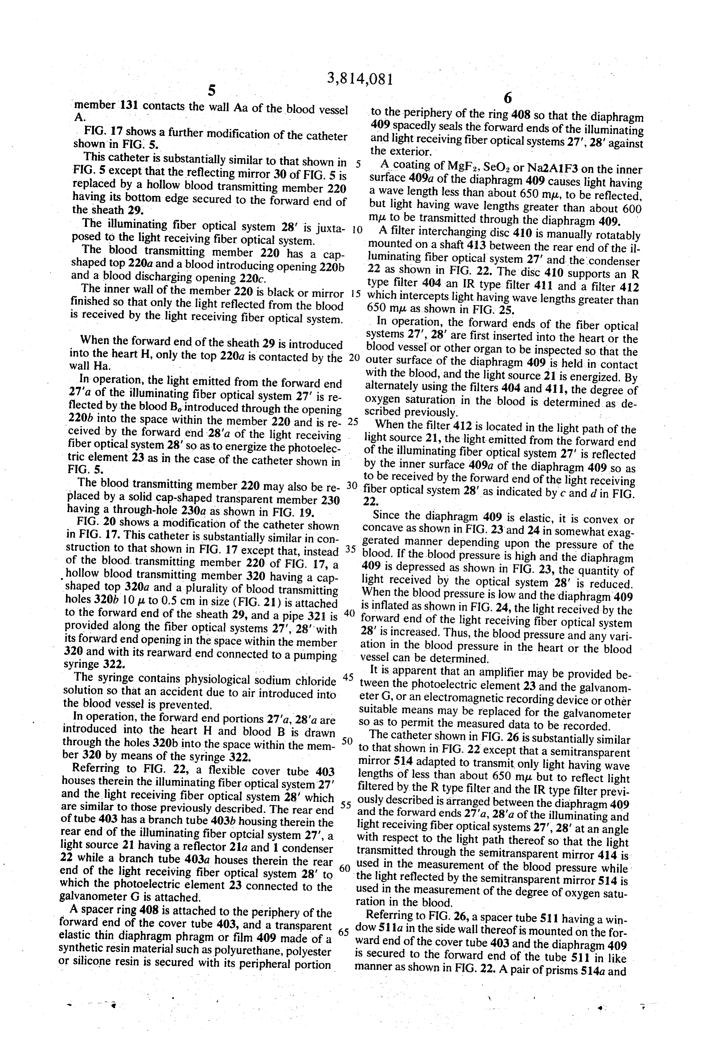
member 131 contacts the wall Aa of the blood vessel to the periphery of the ring 408 so that the diaphragm FIG. 17 shows a further modification of the catheter 409 spacedly seals the forward ends of the illuminating shown in FIG. 5. and light receiving fiber optical systems 27, 28' against This catheter is substantially similar to that shown in the exterior.
FIG. 5 except that the reflecting mirror 30 of FIG. 5 is A coating of MgF2, SeO, or Na2A1F3 on the inner replaced by a hollow blood transmitting member 220 surface 409a of the diaphragm 409 causes light having having its bottom edge secured to the forward end of abutwave length less than about 650 mpu, to be reflected, light having wave lengths greater than about 600 the sheath 29.
The illuminating fiber optical system 28' is juxta O muA to be transmitted through the diaphragm 409. filter interchanging disc 410 is manually rotatably posed to the light receiving fiber optical system. mounted on a shaft 413 between the rear end of the il The blood transmitting member 220 has a cap luminating shaped top 220a and a blood introducing opening 220b 22 as shownfiber in optical system 27' and the condenser
FIG. 22. The disc 410 supports an R and a blood discharging opening 220c.
The inner wall of the member 220 is black or mirror 15 type filter 404 an IR type filter 411 and a filter 412 finished so that only the light reflected from the blood whichmuintercepts light having wavelengths greater than is received by the light receiving fiber optical system. 650 as shown in FIG. 25.
In operation, the forward ends of the fiber optical systems
When the forward end of the sheath 29 is introduced blood vessel 27", 28' are first inserted into the heart or the into the heart H, only the top 220a is contacted by the outer or other organ to be inspected so that the wall Ha. ... surface of the diaphragm 409 is held in contact In operation, the light emitted from the forward end with the blood, and the light source 21 is energized. By alternately using the filters 404 and 411, the degree of 27'a of the illuminating fiber optical system 27' is re oxygen saturation flected by the blood Bo introduced through the opening scribed previously. in the blood is determined: as de 220b into the space within the member 220 and is re 25 When the filter 412 is located in the light path of the ceived by the forward end 28'a of the light receiving . light fiber optical system 28' so as to energize the photoelec of thesource 21, the light emitted from the forward end illuminating fiber optical system 27' is reflected tric element 23 as in the case of the catheter shown in by the inner surface 409a of the diaphragm 409 so as
The blood transmitting member 220 may also be re 30 fiber to be received by the forward end of the light receiving placed by a solid cap-shaped transparent member 230 22. optical system 28' as indicated by c and d in FIG. having a through-hole 230a as shown in FIG. 19. Since the diaphragm 409 is elastic, it is convex or FIG. 20 shows a modification of the catheter shown concave in FIG. 17. This catheter is substantially similar in con gerated manner as shown in FIG. 23 and 24 in somewhat exag struction to that shown in FIG. 17 except that, instead 35 blood. If the blooddepending pressure upon the pressure of the is high and the diaphragm of the blood transmitting member 220 of FIG. 17, a 409 is depressed as shown in FIG.
hollow blood transmitting member 320 having a cap light received by the optical system23,28' the quantity of is reduced.
shaped top 320a and a plurality of blood transmitting When the blood pressure is low and the diaphragm holes 320b 10p to 0.5 cm in size (FIG. 21) is attached 40 is inflated as shown in FIG. 24, the light received by409 the to the forward end of the sheath 29, and a pipe 321 is provided along the fiber optical systems 27, 28' with forward end of the light receiving fiber optical system 28' is increased. Thus, the blood pressure and any vari its forward end opening in the space within the member ation in the blood pressure in the heart or the blood 320 and with its rearward end connected
to a pumping
The syringe contains physiological sodium chloride 45 tween the photoelectric element 23 and theprovided It is apparent that an amplifier may be be galvanom solution so that an accident due to air introduced into eter G, or an electromagnetic recording device or other the blood vessel is prevented. suitable means may be replaced for the galvanometer In operation, the forward end portions 27'a, 28'a are so as to permit the measured data to be recorded. introduced into the heart H and blood B is drawn 50 The through the holes 320b into the space within the mem to thatcatheter shown in FIG. 26 is substantially similar shown in FIG. 22 except that a semitransparent ber 320 by means of the syringe 322. mirror 514 adapted to transmit only light having wave Referring to FIG. 22, a flexible cover tube 403 lengths of less than about 650 mu, but to reflect light houses therein the illuminating fiber optical system 27 filtered by the R type filter and the IR type filter previ and the light receiving fiber optical system 28' which 55 ously are similar to those previously described. The rear end and the forwardisends described arranged between the diaphragm 409 27a, 28'a of the illuminating and of tube 403 has a branch tube 403b housing therein the light receiving fiber optical systems 27, 28' at an angle rear end of the illuminating fiber opticial system 27', a with respect to the light path thereof so that the light light source 21 having a reflector 21a and 1 condenser transmitted through the semitransparent mirror 414 is 22 while a branch tube 403a houses therein the rear 60 used in the measurement of the blood end of the light receiving fiber optical system 28' to the light reflected by the semitransparent mirror 514 pressure while which the photoelectric element 23 connected to the used in the measurement of the degree of oxygen satuis galvanometer G is attached. ration in the blood.
A spacer ring 408 is attached to the periphery of the Referring to FIG. 26, a spacer tube 511 having a win forward end of the cover tube 403, and a transparent 65 dow elastic thin diaphragm phragm or film 409 made of a ward511a in the side wall thereof is mounted on the for synthetic resin material such as polyurethane, polyester is secured tothethecover
forward end of the tube 511 in like or silicone resin is secured with its peripheral portion manner as shown in FIG.22. A pair of prisms 514a and
Page 10
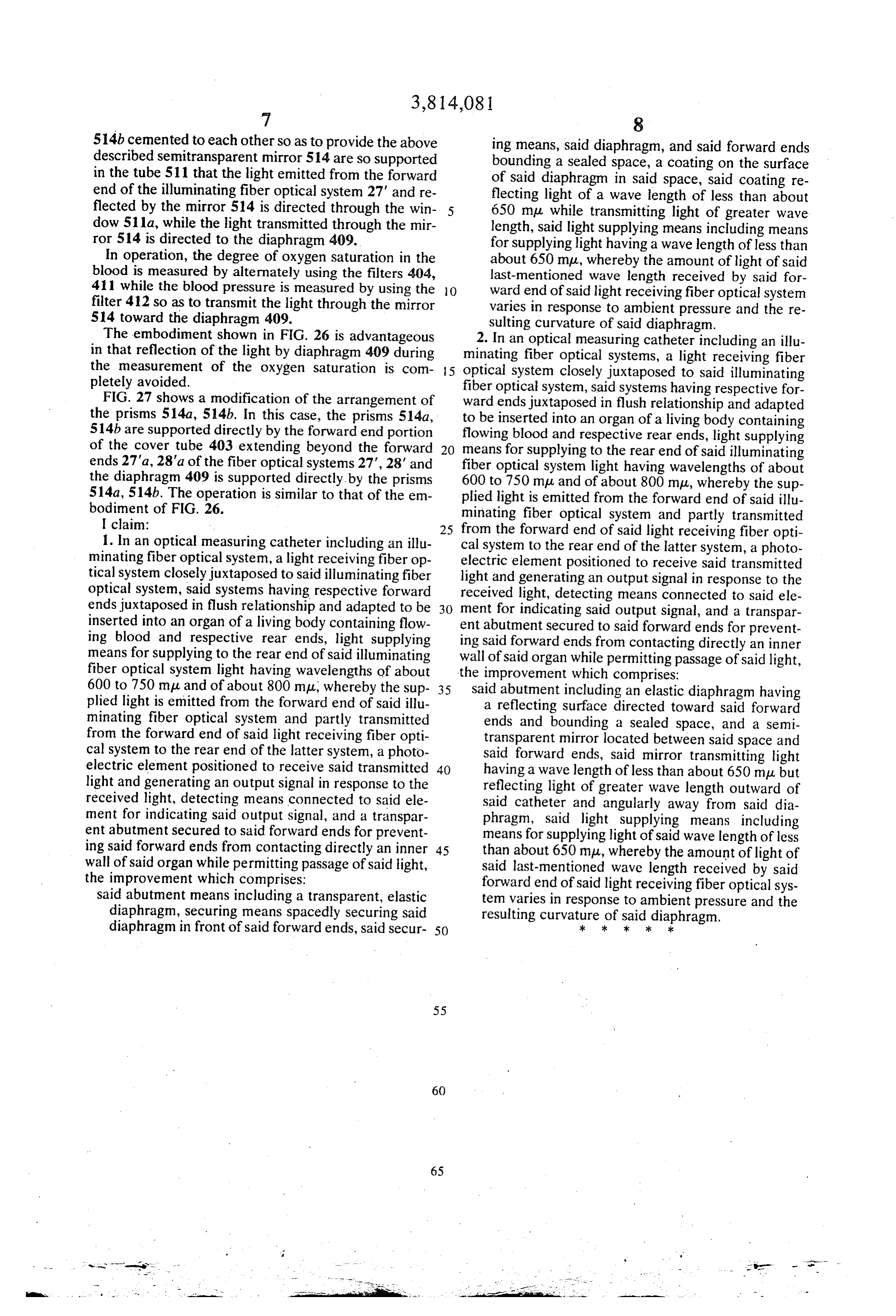
514b cemented to each other so as to provide the above ing means, said diaphragm, and said forward ends described semitransparent mirror 514 are so supported bounding a sealed space, a coating on the surface in the tube 511 that the light emitted from the forward of said diaphragm in said space, said coating re end of the illuminating fiber optical system 27' and re flecting light of a wave length of less than about flected by the mirror 514 is directed through the win 5 650 mpu while transmitting light of greater wave dow 5.11a, while the light transmitted through the mir length, said light supplying means including means ror 514 is directed to the diaphragm 409. for supplying light having a wave length of less than In operation, the degree of oxygen saturation in the about 650 mpu, whereby the amount of light of said blood is measured by alternately using the filters 404, last-mentioned wave length received by said for 411 while the blood pressure is measured by using the O ward end of said light receiving fiber optical system filter 412 so as to transmit the light through the mirror varies in response to ambient pressure and the re 514 toward the diaphragm 409. sulting curvature of said diaphragm. The embodiment shown in FIG. 26 is advantageous 2. In an optical measuring catheter including an illu in that reflection of the light by diaphragm 409 during minating fiber optical systems, a light receiving fiber the measurement of the oxygen saturation is com 5 optical system closely juxtaposed to said illuminating pletely avoided. fiber optical system, said systems having respective for FIG. 27 shows a modification of the arrangement of ward ends juxtaposed in flush relationship and adapted the prisms 514a, 514b. In this case, the prisms 514a, to be inserted into an organ of a living body containing 514b are supported directly by the forward end portion flowing blood and respective rear ends, light supplying of the cover tube 403 extending beyond the forward means for supplying to the rear end of said illuminating ends 27'a, 28'a of the fiber optical systems 27, 28' and fiber optical system light having wavelengths of about the diaphragm 409 is supported directly by the prisms 600 to 750 mpu and of about 800 mpu, whereby the sup 514a, 514b. The operation is similar to that of the em plied light is emitted from the forward end of said illu bodiment of FIG. 26. minating fiber optical system and partly transmitted claim: 25 from the forward end of said light receiving fiber opti 1. In an optical measuring catheter including an illu cal system to the rear end of the latter system, a photo minating fiber optical system, a light receiving fiber op electric tical system closely juxtaposed to said illuminating fiber light andelement positioned to receive said transmitted generating an output signal in response to the optical system, said systems having respective forward ends juxtaposed in flush relationship and adapted to be 30 received light, detecting means connected to said ele ment for indicating said output signal, and a transpar inserted into an organ of a living body containing flow ing blood and respective rear ends, light supplying ent abutment secured to said forward ends for prevent. ing said forward ends from contacting directly an inner means for supplying to the rear end of said illuminating wall of said organ while permitting passage of said light, fiber optical system light having wavelengths of about the improvement which comprises:
600 to 750 mpu and of about 800 mpu, whereby the sup 35 said abutment including an elastic diaphragm having plied light is emitted from the forward end of said illu a reflecting surface directed toward said forward minating fiber optical system and partly transmitted ends and bounding a sealed space, and a semi from the forward end of said light receiving fiber opti transparent mirror located between said space and cal system to the rear end of the latter system, a photo said forward ends, said mirror transmitting light electric element positioned to receive said transmitted 40 having a wave length of less than about 650 mp but light and generating an output signal in response to the reflecting light of greater wave length outward of received light, detecting means connected to said ele said catheter and angularly away from said dia ment for indicating said output signal, and a transpar phragm, said light supplying means including ent abutment secured to said forward ends for prevent means for supplying light of said wave length of less ing said forward ends from contacting directly an inner 45 than about 650 mpu, whereby the amount of light of wall of said organ while permitting passage of said light, said last-mentioned wave length received by said the improvement which comprises: forward end of said light receiving fiber optical sys said abutment means including a transparent, elastic tem varies in response to ambient pressure and the diaphragm, securing means spacedly securing said resulting curvature of said diaphragm. diaphragm in front of said forward ends, said secur 50 ; :k k - k
Provenance
- Collection
- Cited prior art
- Original PDF
- patentimages.storage.googleapis.com →
- Filed
- 1972-03-30
- Pages
- 10
- Method
- pdftotext (the PDF's own text layer) + pdftoppm 300dpi page scans
- Source
- Google Patents bibliographic record
- Granted
- 1974-06-04
- Inventors
- T Mori; Olympus Optical Co Ltd
- Transcribed from
- patentimages.storage.googleapis.com →