memo
WFC 417 — WFC 417
Page 0
memo WFC417
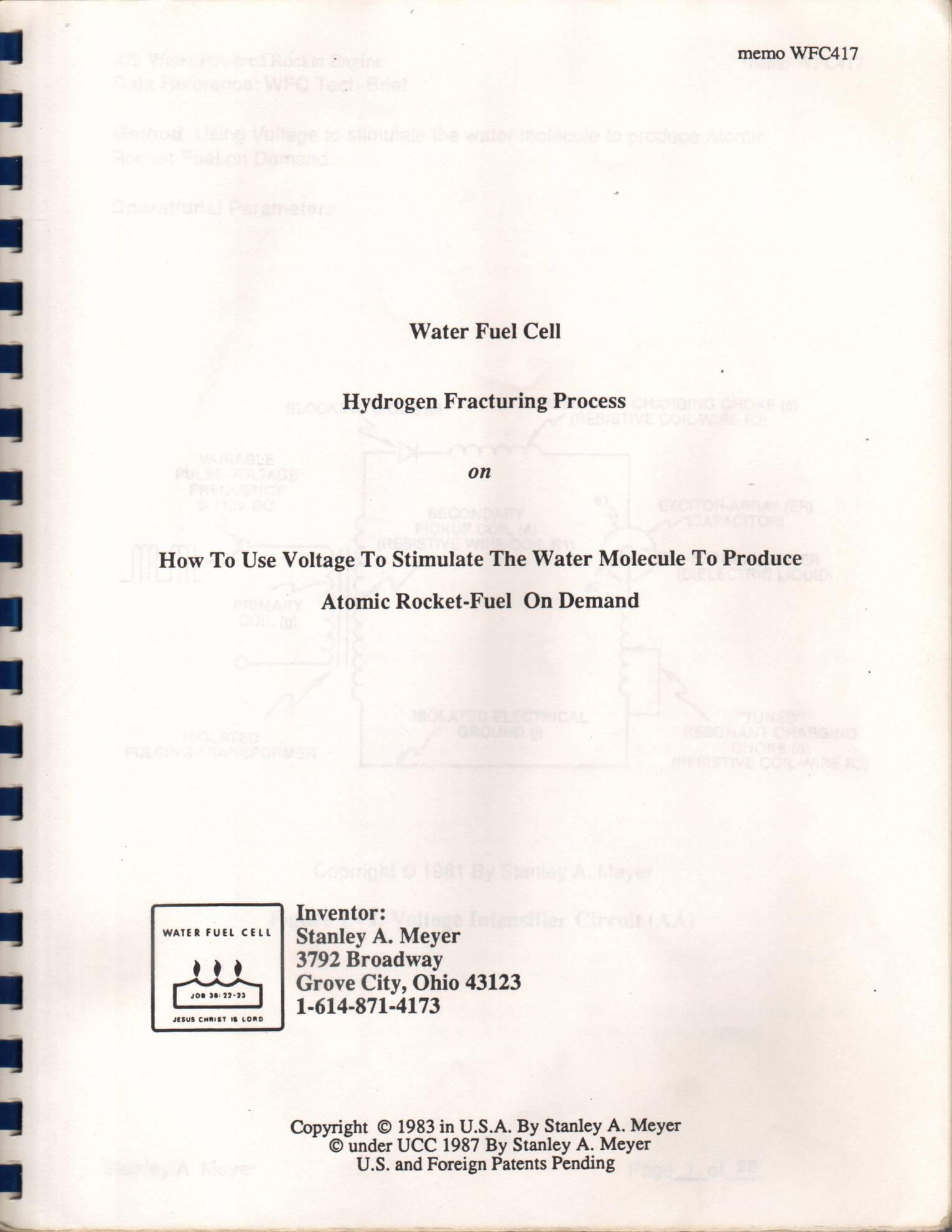
Water Fuel Cell
Hydrogen Fracturing Process
How To Use Voltage To Stimulate The Water Molecule To Produce Atomic Rocket-Fuel On Demand
Inventor:
WATER FUEL CELL Stanley A. Meyer »,2a 3792 Broadway
Grove City, Ohio 43123
JESUS CHRIST 18 LORD
Copyright © 1983 in U.S.A. By Stanley A. Meyer © under UCC 1987 By Stanley A. Meyer U.S. and Foreign Patents Pending
Page 1
RE: Water Powered Rocket Engine memo WFC417 Data Reference: WFC Tech-Brief
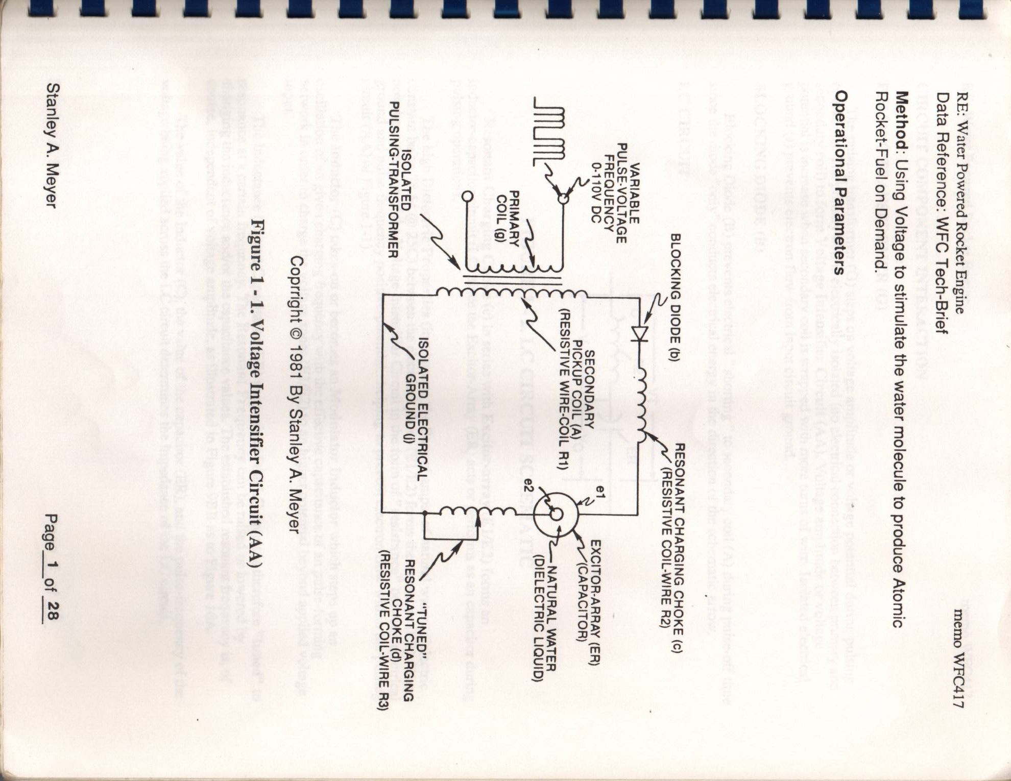
Method: Using Voltage to stimulate the water molecule to produce Atomic Rocket-Fuel on Demand.
Operational Parameters
RESONANT CHARGING CHOKE (c) (b) (RESISTIVE COIL-WIRE R2)
VARIABLE
rOTiOV be EXCITOR-ARRAY (ER)
SECONDARY
PICKUP COIL (A) (GAPAGITOR)
(RESISTIVE WIRE-COIL R1)
NATURAL WATER
(DIELECTRIC LIQUID)
IMUM:
PRIMARY
COIL (g)
Me souarepsiecraca, tf) S -Tunepe
ISOLATED N
PULSING-TRANSFORMER CHOKE (d)
(RESISTIVE COIL-WIRE R3)
Coprright © 1981 By Stanley A. Meyer
Figure 1 - 1. Voltage Intensifier Circuit (AA)
Stanley A. Meyer Page_1 of 28
Page 2
RE: Water Powered Rocket Engine memo WFC417
CIRCUIT COMPONENT INTERACTION
PULSING TRANSFORMER (G)
The pulsing transformer (G) steps up voltage amplitude or voltage potential during pulsing operations. The primary coil is electrically isolated (no electrical connection between primary and secondary coil) to form Voltage Intensifier Circuit (AA). Voltage amplitude or voltage potential is increase when secondary coil is wrapped with more turns of wire. Isolated electrical ground (J) prevents electron flow from input circuit ground.
BLOCKING DIODE (B)
Blocking Diode (B) prevents electrical " shorting " to secondary coil (A) during pulse-off time since the diode "only" conducts electrical energy in the direction of the schematic arrow.
LC CIRCUIT
FIGURE 1 - 2. LC CIRCUIT SCHEMATIC
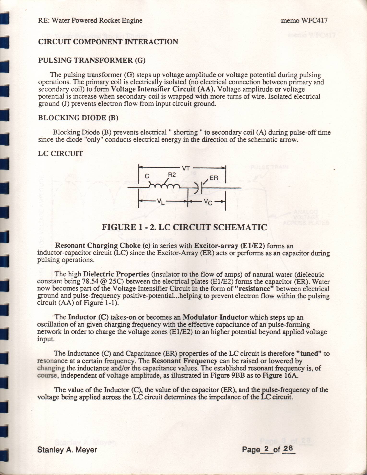
Resonant Charging Choke (c) in series with Excitor-array (E1/E2) forms an inductor-capacitor circuit (LC) since the Excitor-Array (ER) acts or performs as an capacitor during pulsing operations.
The high Dielectric Properties (insulator to the flow of amps) of natural water (dielectric constant being 78.54 @ 25C) between the electrical plates (E1/E2) forms the capacitor (ER). Water now becomes part of the Voltage Intensifier Circuit in the form of "resistance" between electrical ground and pulse-frequency positive-potential...helping to prevent electron flow within the pulsing circuit (AA) of Figure 1-1).
‘The Inductor (C) takes-on or becomes an Modulator Inductor which steps up an oscillation of an given charging frequency with the effective capacitance of an pulse-forming network in order to charge the voltage zones (E1/E2) to an higher potential beyond applied voltage input.
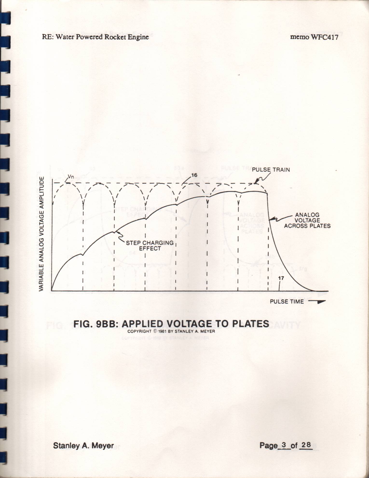
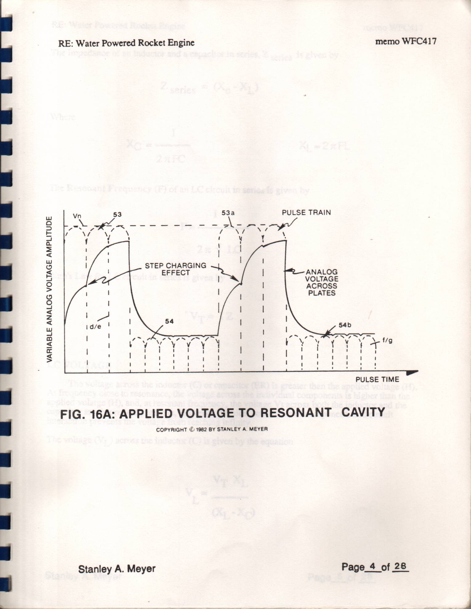
The Inductance (C) and Capacitance (ER) properties of the LC circuit is therefore "tuned" to resonance at a certain frequency. The Resonant Frequency can be raised or lowered by changing the inductance and/or the capacitance values. The established resonant frequency is, of course, independent of voltage amplitude, as illustrated in Figure 9BB as to Figure 16A.
The value of the Inductor (C), the value of the capacitor (ER), and the pulse-frequency of the | voltage being applied across the LC circuit determines the impedance of the LC circuit.
Stanley A. Meyer Page_2 of 28
Page 3
RE: Water Powered Rocket Engine memo WFC417
VARIABLE ANALOG VOLTAGE AMPLITUDE
PULSE TRAIN
fm ae; | apaae
ANALOG
VOLTAGE
ACROSS PLATES
STEP CHARGING
EFFECT
PULSE TIME ——
FIG. 9BB: APPLIED VOLTAGE TO PLATES
COPYRIGHT © 1981 BY STANLEY A. MEYER
Stanley A. Meyer Page_3 of 28
Page 4
VARIABLE ANALOG VOLTAGE AMPLITUDE
RE: Water Powered Rocket Engine memo WFC417 | Vn 53 53a PULSE TRAIN
PULSE TIME
FIG. 16A: APPLIED VOLTAGE TO RESONANT CAVITY
COPYRIGHT © 1982 BY STANLEY A. MEYER
Stanley A. Meyer Page_4 of 28 |
Page 5
RE: Water Powered Rocket Engine memo WFC417
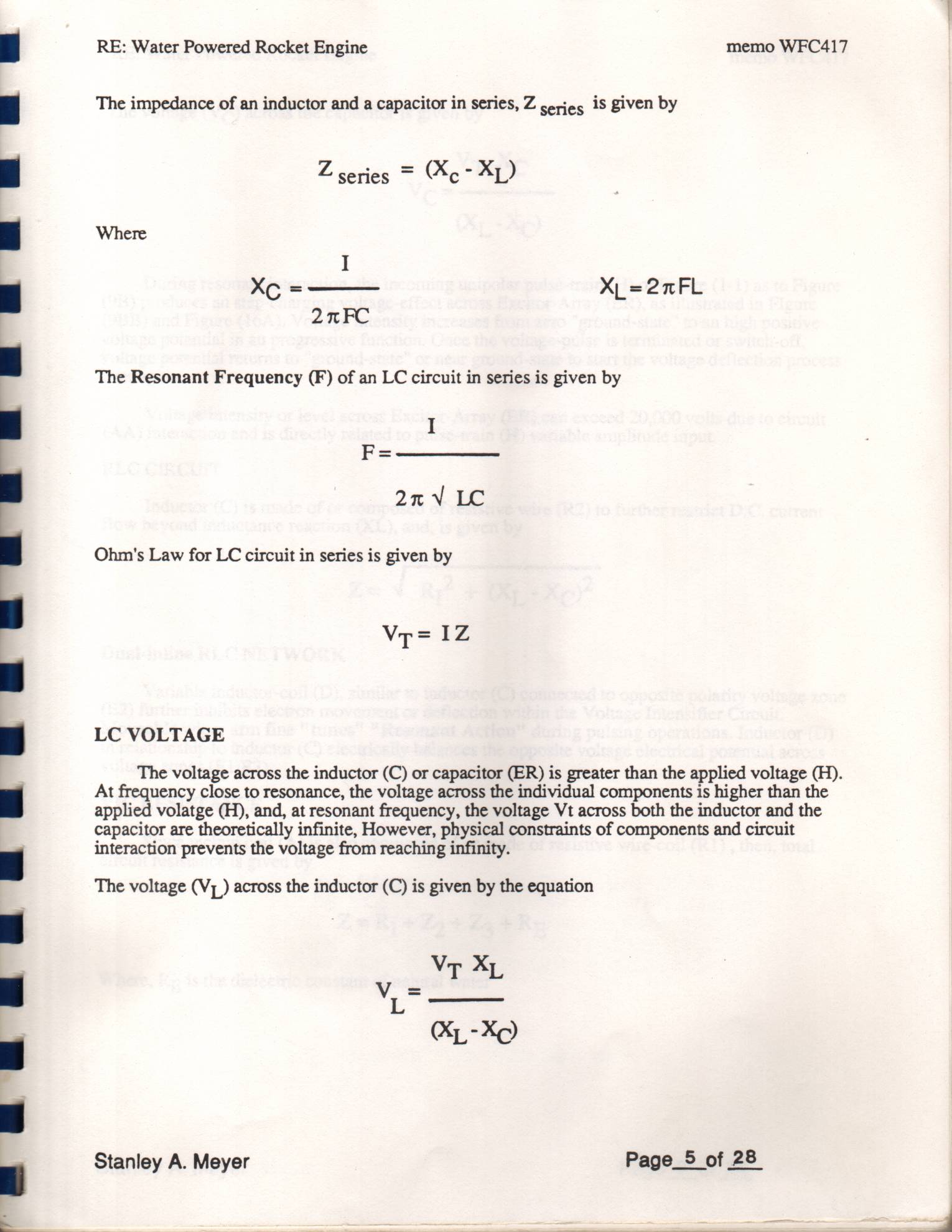
The impedance of an inductor and a capacitor in series, Z cerieg is given by Z series = (Xo - XL)
Where
The Resonant Frequency (F) of an LC circuit in series is given by
Ohm's Law for LC circuit in series is given by
LC VOLTAGE
The voltage across the inductor (C) or capacitor (ER) is greater than the applied voltage (H). At frequency close to resonance, the voltage across the individual components is higher than the applied volatge (H), and, at resonant frequency, the voltage Vt across both the inductor and the capacitor are theoretically infinite, However, physical constraints of components and circuit interaction prevents the voltage from reaching infinity.
The voltage (Vj) across the inductor (C) is given by the equation
Stanley A. Meyer Page_5 of 28.
Page 6
RE: Water Powered Rocket Engine memo WFC417
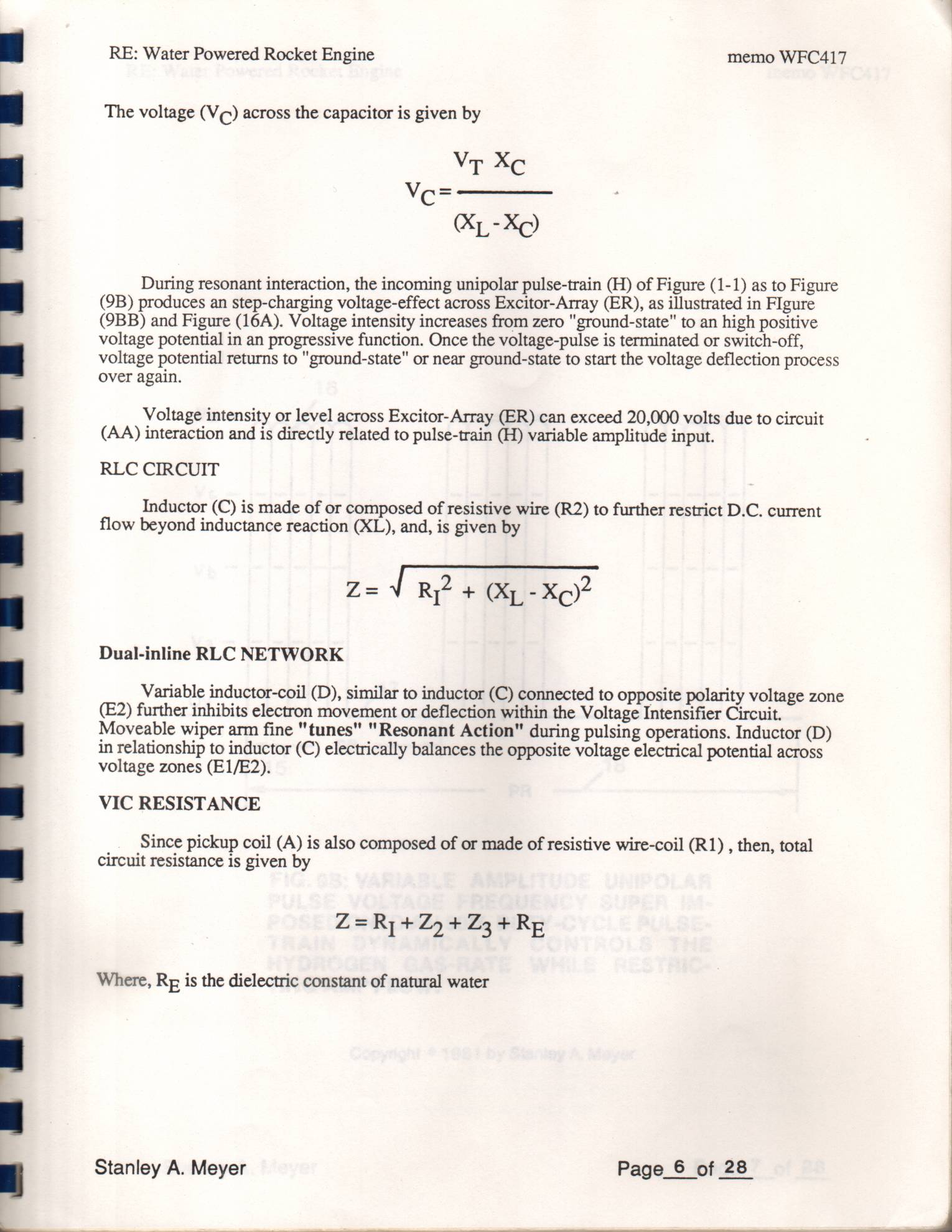
The voltage (Vc) across the capacitor is given by
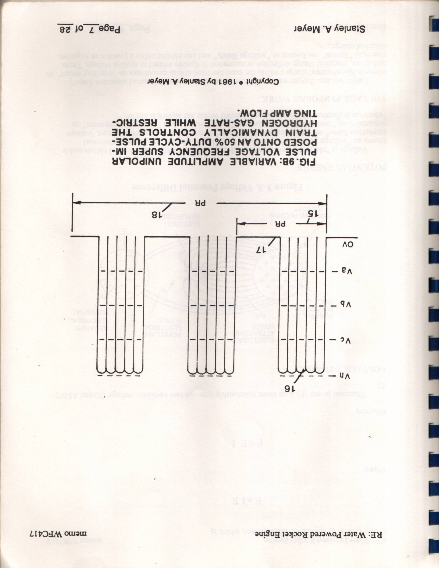
During resonant interaction, the incoming unipolar pulse-train (H) of Figure (1-1) as to Figure
(9B) produces an step-charging voltage-effect across Excitor-Array (ER), as illustrated in Figure (9BB) and Figure (16A). Voltage intensity increases from zero "ground-state" to an high positive voltage potential in an progressive function. Once the voltage-pulse is terminated or switch-off, voltage potential returns to "ground-state" or near ground-state to start the voltage deflection process
over again.
Voltage intensity or level across Excitor-Array (ER) can exceed 20,000 volts due to circuit (AA) interaction and is directly related to pulse-train (H) variable amplitude input.
RLC CIRCUIT
Inductor (C) is made of or composed of resistive wire (R2) to further restrict D.C. current flow beyond inductance reaction (XL), and, is given by
Dual-inline RLC NETWORK
Variable inductor-coil (D), similar to inductor (C) connected to opposite polarity voltage zone (E2) further inhibits electron movement or deflection within the Voltage Intensifier Circuit. Moveable wiper arm fine "tunes" "Resonant Action" during pulsing operations. Inductor (D) in relationship to inductor (C) electrically balances the opposite voltage electrical potential across voltage zones (E1/E2).
VIC RESISTANCE
Since pickup coil (A) is also composed of or made of resistive wire-coil (R1) , then, total circuit resistance is given by
Where, Rp is the dielectric constant of natural water
Stanley A. Meyer Page_6 of 28
Page 7
RE: Water Powered Rocket Engine memo WFC417
FIG. 9B: VARIABLE AMPLITUDE UNIPOLAR
PULSE VOLTAGE FREQUENCY SUPER IM-
POSED ONTO AN 50% DUTY-CYCLE PULSE-
TRAIN DYNAMICALLY CONTROLS THE
HYDROGEN GAS-RATE WHILE RESTRIC-
TING AMP FLOW.
Copyright © 1981 by Stanley A Meyer
Stanley A. Meyer Page_7 of 28
Page 8
RE: Water Powered Rocket Engine
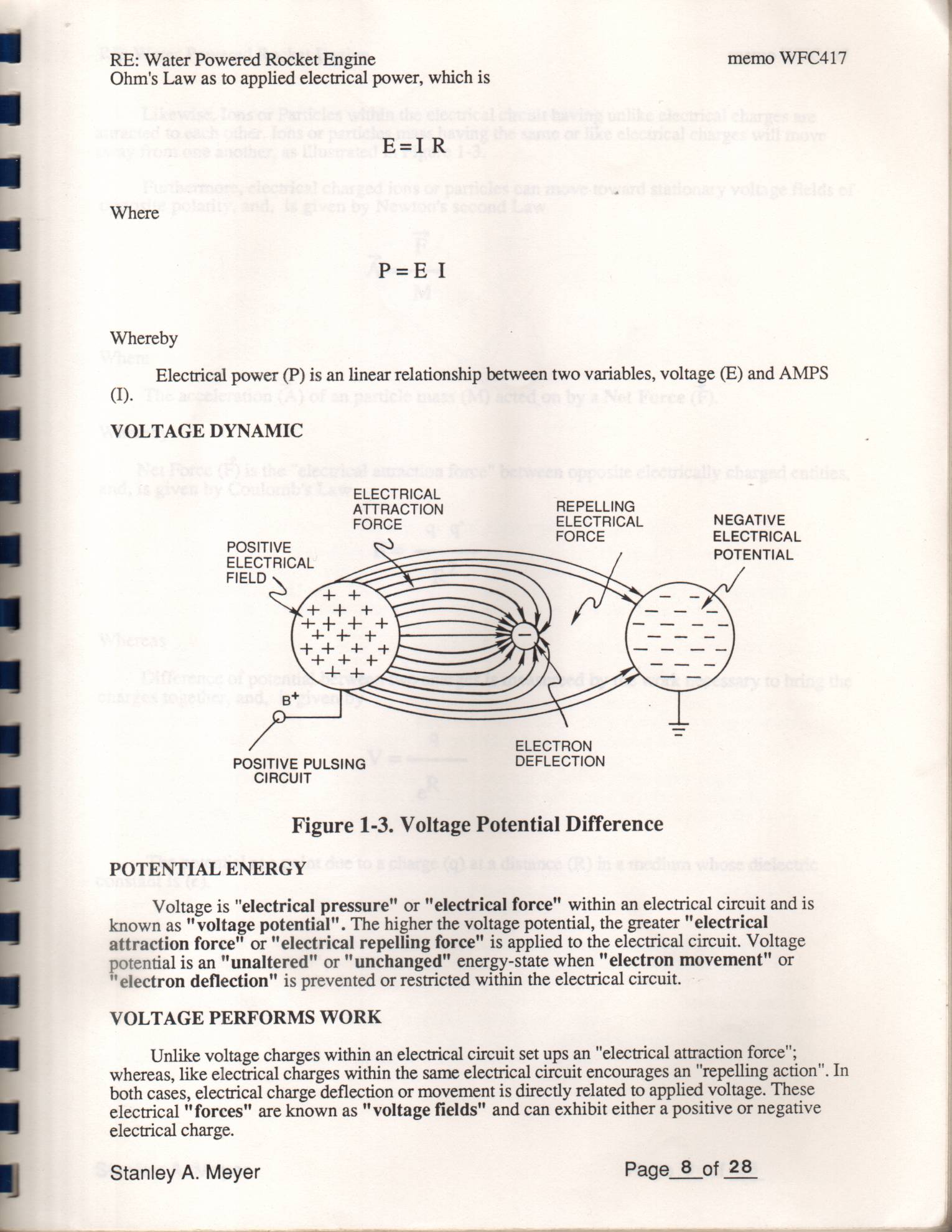
Ohm's Law as to applied electrical power, which is
memo WFC417
NEGATIVE
ELECTRICAL
POTENTIAL
Where
Whereby
Electrical power (P) is an linear relationship between two variables, voltage (E) and AMPS
VOLTAGE DYNAMIC
ELECTRICAL
ATTRACTION REPELLING
FORCE ELECTRICAL
POSITIVE Bence
ELECTRICAL
FIELD
ELECTRON
POSITIVE PULSING DEFLECTION
CIRCUIT
Figure 1-3. Voltage Potential Difference
POTENTIAL ENERGY
Voltage is "electrical pressure" or "electrical force" within an electrical circuit and is known as "voltage potential". The higher the voltage potential, the greater "electrical attraction force" or "electrical repelling force" is applied to the electrical circuit. Voltage potential is an "unaltered" or "unchanged" energy-state when "electron movement" or
"electron deflection" is prevented or restricted within the electrical circuit.
VOLTAGE PERFORMS WORK
Unlike voltage charges within an electrical circuit set ups an "electrical attraction force"; whereas, like electrical charges within the same electrical circuit encourages an "repelling action". In both cases, electrical charge deflection or movement is directly related to applied voltage. These electrical "forces" are known as "voltage fields" and can exhibit either a positive or negative
electrical charge.
Stanley A. Meyer Page_8 of 28
Page 9
RE: Water Powered Rocket Engine memo WFC417
Likewise, Ions or Particles within the electrical circuit having unlike electrical charges are attracted to each other. Ions or particles mass having the same or like electrical charges will move away from one another, as illustrated in Figure 1-3.
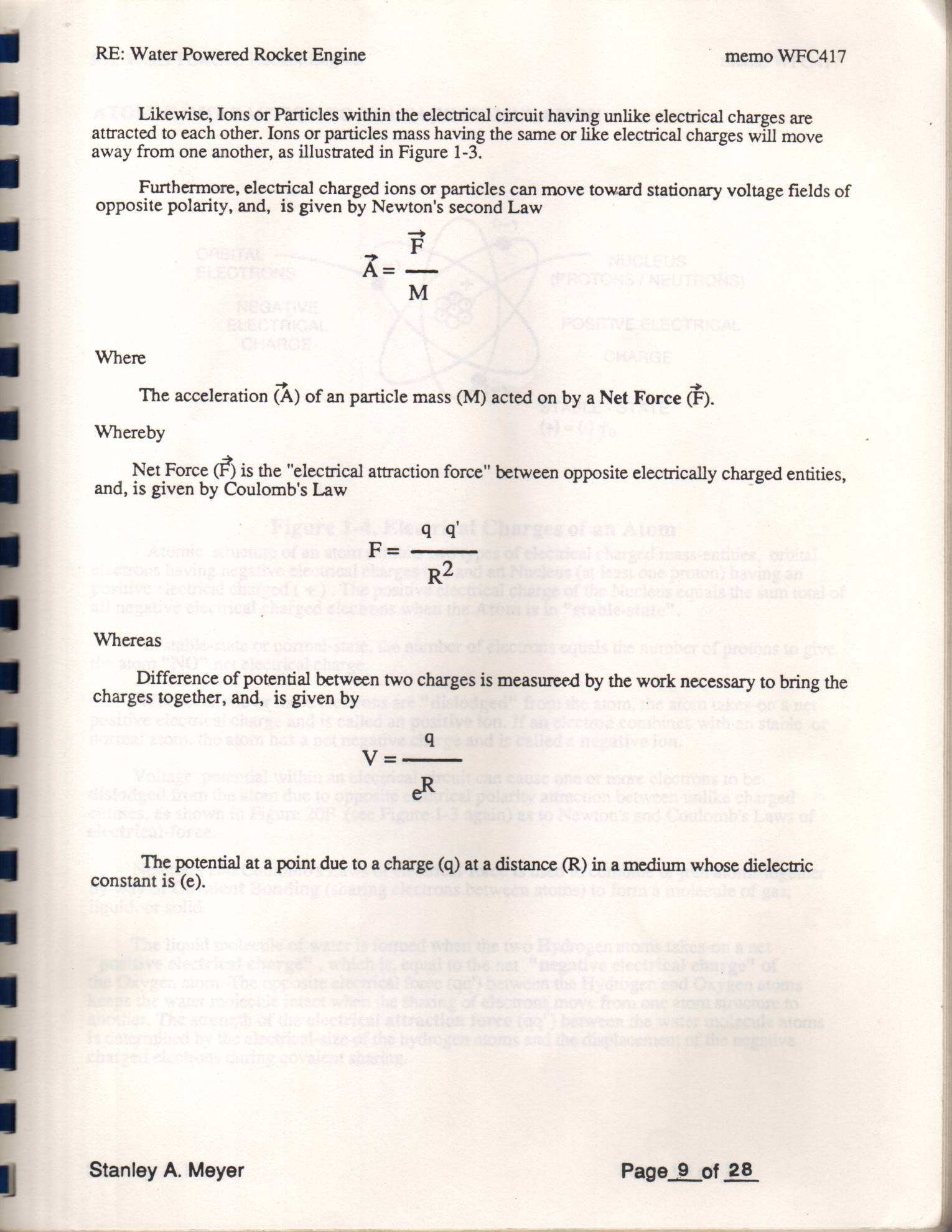
Furthermore, electrical charged ions or particles can move toward stationary voltage fields of opposite polarity, and, is given by Newton's second Law
ioe a
Where
The acceleration (A) of an particle mass (M) acted on by a Net Force ®.
Whereby
Net Force €) is the "electrical attraction force" between opposite electrically charged entities, and, is given by Coulomb's Law
Whereas
Difference of potential between two charges is measureed by the work necessary to bring the charges together, and, is given by
The potential at a point due to a charge (q) at a distance (R) in a medium whose dielectric constant is (e).
Stanley A. Meyer Page_9 of 28
Page 10
RE: Water Powered Rocket Engine memo WFC417
ATOMIC INTERACTION TO VOLTAGE STIMULATION
ORBITAL NUCLEUS
ELECTRONS ~~ (PROTONS / NEUTRONS)
NEGATIVE
ELECTRICAL
CHARGE
POSITIVE ELECTRICAL
CHARGE
STABLE - STATE
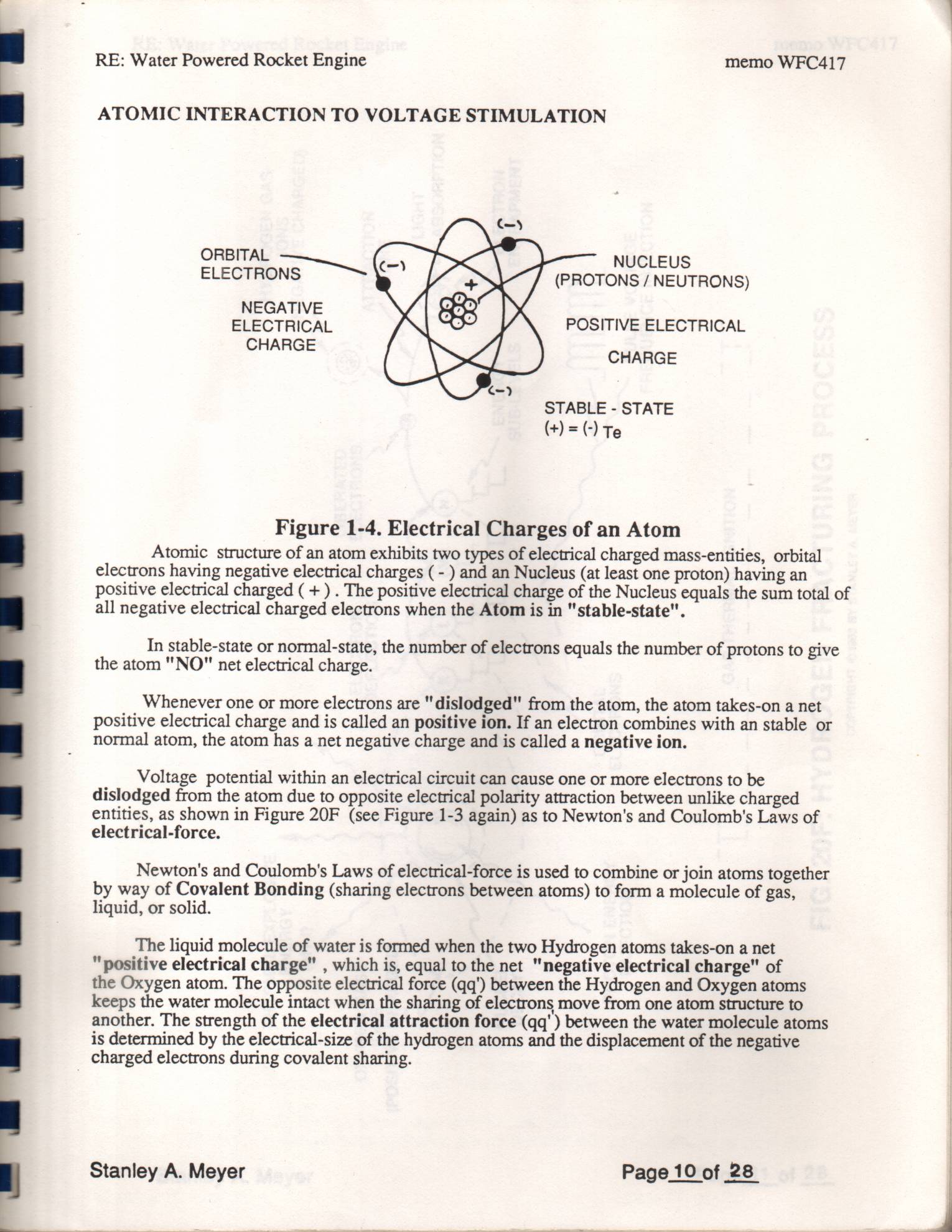
Figure 1-4. Electrical Charges of an Atom
Atomic structure of an atom exhibits two types of electrical charged mass-entities, orbital electrons having negative electrical charges (- ) and an Nucleus (at least one proton) having an positive electrical charged ( + ) . The positive electrical charge of the Nucleus equals the sum total of all negative electrical charged electrons when the Atom is in "stable-state".
In stable-state or normal-state, the number of electrons equals the number of protons to give the atom "NO" net electrical charge.
Whenever one or more electrons are "dislodged" from the atom, the atom takes-on a net positive electrical charge and is called an positive ion. If an electron combines with an stable or normal atom, the atom has a net negative charge and is called a negative ion.
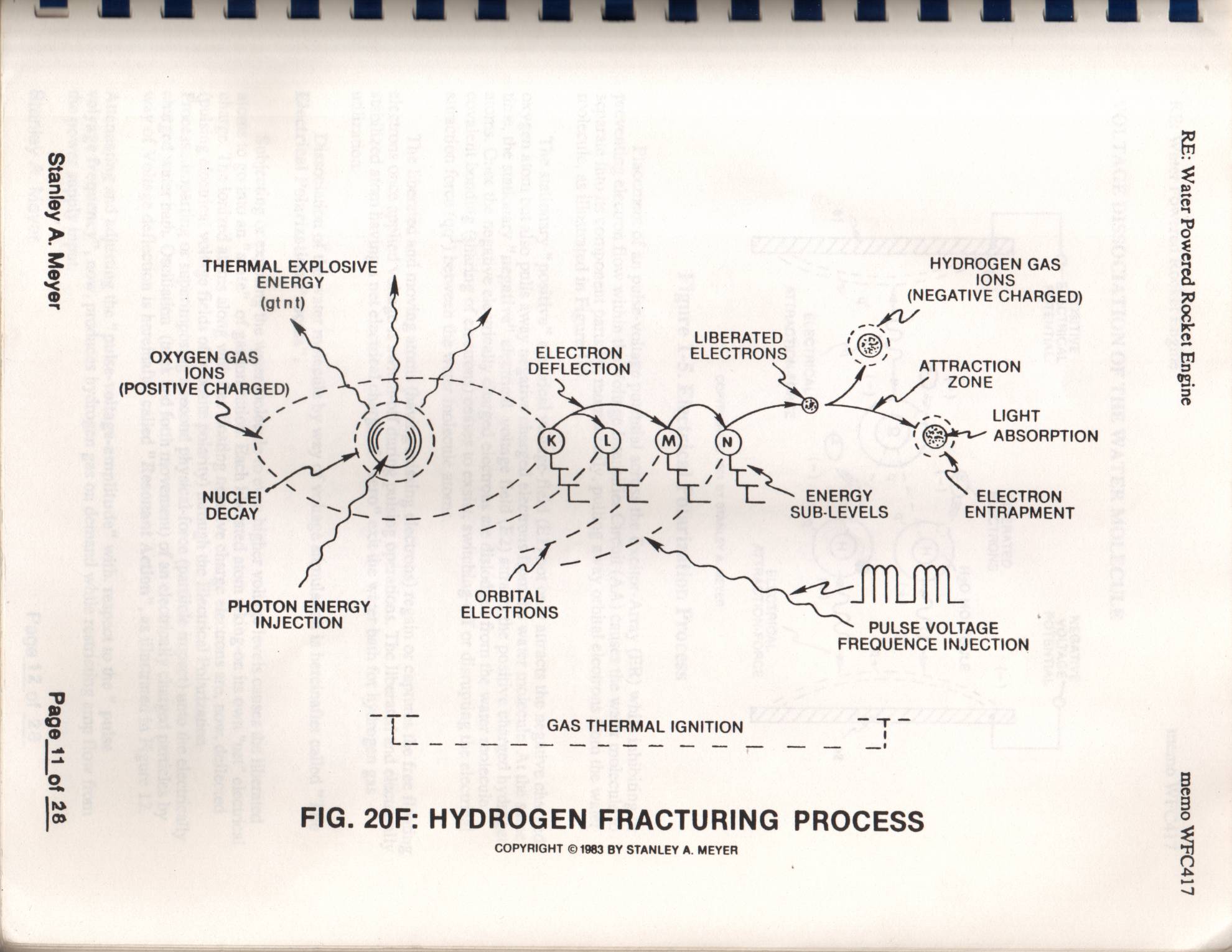
Voltage potential within an electrical circuit can cause one or more electrons to be dislodged from the atom due to opposite electrical polarity attraction between unlike charged entities, as shown in Figure 20F (see Figure 1-3 again) as to Newton's and Coulomb's Laws of
Newton's and Coulomb's Laws of electrical-force is used to combine or join atoms together by way of Covalent Bonding (sharing electrons between atoms) to form a molecule of gas, liquid, or solid.
The liquid molecule of water is formed when the two Hydrogen atoms takes-on a net "positive electrical charge" , which is, equal to the net "negative electrical charge" of the Oxygen atom. The opposite electrical force (qq') between the Hydrogen and Oxygen atoms keeps the water molecule intact when the sharing of electrons move from one atom structure to another. The strength of the electrical attraction force (qq' ) between the water molecule atoms is determined by the electrical-size of the hydrogen atoms and the displacement of the negative charged electrons during covalent sharing.
Stanley A. Meyer Page 10 of 28
Page 11
Johey ‘y Agjueyg
THERMAL EXPLOSIVE a AS
ENERGY NEGATIVE CHARGED!
LIBERATED ‘@)
ELECTRON ELECTRONS Sy, mehr tag: 5 DEFLECTION ~ 1 Byeerion (POSITIVE CHARGED) _ — -“\_ cere ae S a \ oo LIGHT ' ul ABSORPTION
NUCLEI” ~ ~ es e 5 —_ ENERGY - ELECTRON
DECAY i. ect Be B Z SUB-LEVELS ENT
| ims
PHOTON ENERGY erecrioes
INJECTION PULSE VOLTAGE
FREQUENCE INJECTION
7. T = GAS THERMAL IGNITION =a lai
FIG. 20F: HYDROGEN FRACTURING PROCESS
COPYRIGHT © 1983 BY STANLEY A. MEYER
ouidugq 1oFI0y poromog J31e@ AA “TY
LIvOAM OulouT
Page 12
RE: Water Powered Rocket Engine memo WFC417
VOLTAGE DISSOCIATION OF THE WATER MOLECULE
POSITIVE NEGATIVE
ELECTRICAL VOLTAGE
POTENTIAL POTENTIAL
LIBERATED (-)
\ (+) ELECTRONS
H20 MOLECULE /
ELECTRICAL
COPYRIGHT © 1981 BY STANLEY A. MEYER
Figure 1-5. Electrical Polarization Process
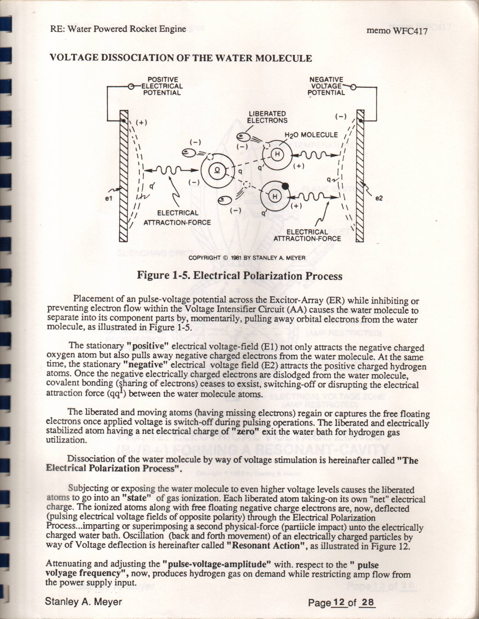
Placement of an pulse-voltage potential across the Excitor-Array (ER) while inhibiting or preventing electron flow within the Voltage Intensifier Circuit (AA) causes the water molecule to separate into its component parts by, momentarily, pulling away orbital electrons from the water molecule, as illustrated in Figure 1-5.
The stationary " positive" electrical voltage-field (E1) not only attracts the negative charged oxygen atom but also pulls away negative charged electrons from the water molecule. At the same time, the stationary "negative" electrical voltage field (E2) attracts the positive charged hydrogen atoms. Once the negative electrically charged electrons are dislodged from the water molecule, covalent bonding (sharing of electrons) ceases to exsist, switching-off or disrupting the electrical attraction force (qq*) between the water molecule atoms.
The liberated and moving atoms (having missing electrons) regain or captures the free floating electrons once applied voltage is switch-off during pulsing operations. The liberated and electrically stabilized atom having a net electrical charge of "zero" exit the water bath for hydrogen gas utilization.
Dissociation of the water molecule by way of voltage stimulation is hereinafter called "The Electrical Polarization Process".
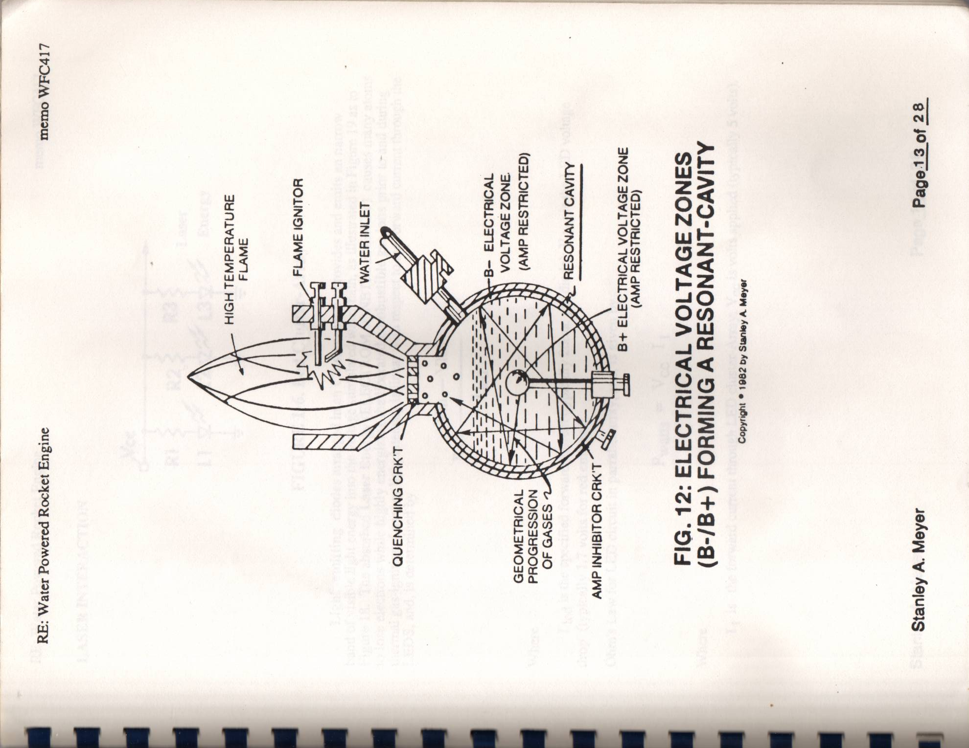
Subjecting or exposing the water molecule to even higher voltage levels causes the liberated atoms to go into an "state" of gas ionization. Each liberated atom taking-on its own "net" electrical charge. The ionized atoms along with free floating negative charge electrons are, now, deflected (pulsing electrical voltage fields of opposite polarity) through the Electrical Polarization Process...imparting or superimposing a second physical-force (partiicle impact) unto the electrically charged water bath. Oscillation (back and forth movement) of an electrically charged particles by way of Voltage deflection is hereinafter called "Resonant Action", as illustrated in Figure 12.
Attenuating and adjusting the " pulse-voltage-amplitude" with. respect to the " pulse volyage frequency", now, produces hydrogen gas on demand while restricting amp flow from the power supply input.
Stanley A. Meyer Page 12 of 28
Page 13
RE: Water Powered Rocket Engine
HIGH TEMPERATURE
FLAME
FLAME IGNITOR
n-B-— ELECTRICAL
VOLTAGE ZONE.
GEOMETRICAL (AMP RESTRICTED)
PROGRESSION
OF GASES
NE RESONANT CAVITY
AMP INHIBITOR CRK'T SS
B+ ELECTRICAL VOLTAGE ZONE
(AMP RESTRICTED)
FIG. 12: ELECTRICAL VOLTAGE ZONES
(B-/B+) FORMING A RESONANT-CAVITY
Copyright * 1982 by Stanley A Meyer memo WFC417
Stanley A. Meyer Page.13 of 28°
Page 14
RE: Water Powered Rocket Engine memo WFC417
LASER INTERACTION
Nec
Laser eo L3yW27%_—_ Energy
FIGURE 1-6. Led Cluster-Array
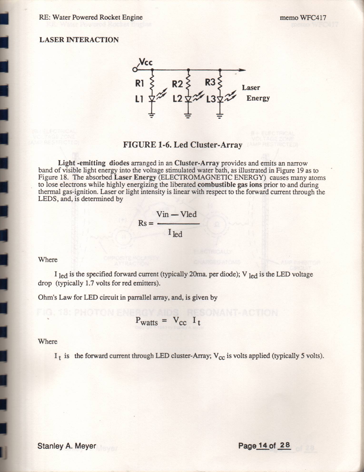
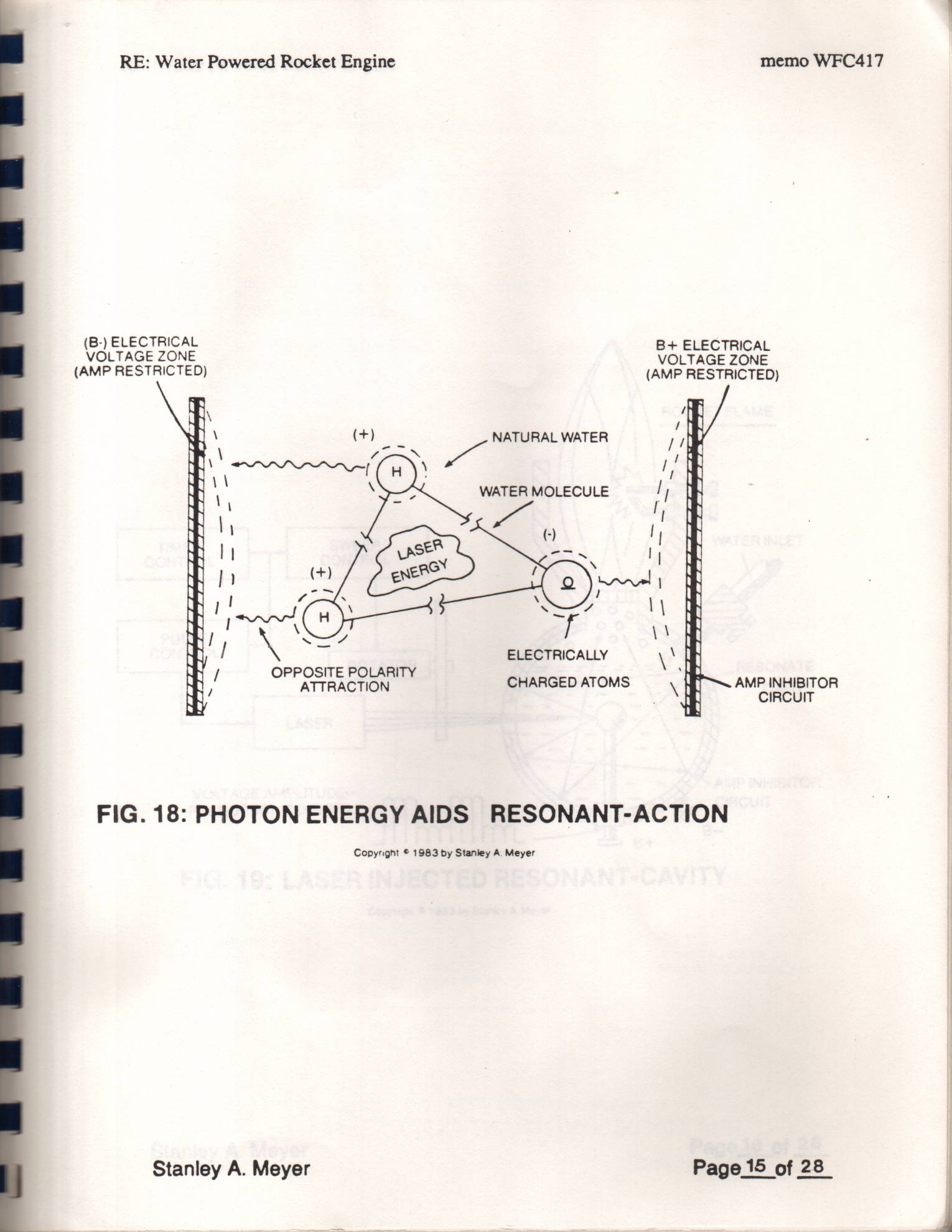
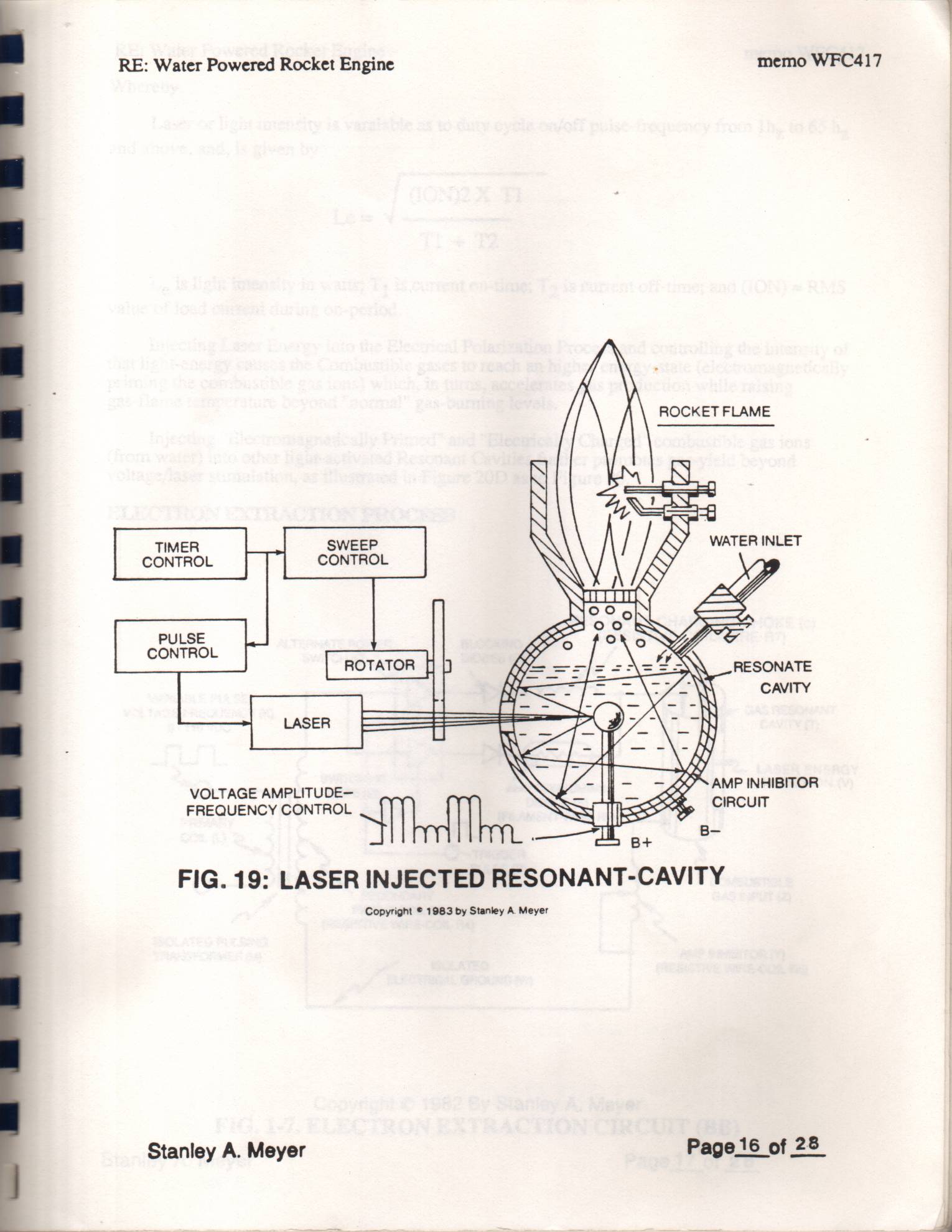
Light -emitting diodes arranged in an Cluster-Array provides and emits an narrow band of visible light energy into the voltage stimulated water bath, as illustrated in Figure 19 as to Figure 18. The absorbed Laser Energy (ELECTROMAGNETIC ENERGY) causes many atoms to lose electrons while highly energizing the liberated combustible gas ions prior to-and during thermal gas-ignition. Laser or light intensity is linear with respect to the forward current through the LEDS, and, is determined by
Vin — Vled
Ted
Where
I jeq is the specified forward current (typically 20ma. per diode); V jeg is the LED voltage drop (typically 1.7 volts for red emitters).
Ohm's Law for LED circuit in parrallel array, and, is given by
Pwatts = Veco It
Where
I, is the forward current through LED cluster-Array; Vo¢ is volts applied (typically 5 volts). Stanley A. Meyer Page 14 of 28
Page 15
RE: Water Powered Rocket Engine memo WFC417 ene os execTacAL
LTAGE ZONE
(AMP RESTRICTED) (AMP RESTRICTED)
ELECTRICALLY
PPOSITE POLARITY
ATTRACTION CHARGED ATOMS AMP INHIBITOR
CIRCUIT
FIG. 18: PHOTON ENERGY AIDS RESONANT-ACTION
Copyright © 1983 by Stanley A. Meyer Stanley A. Meyer Page15 of 28_
Page 16
RE: Water Powered Rocket Engine memo WFC417
TIMER SWEET! WATER INLET
CONTROL
PULSE jy ~
CONTROL
= = RESONATE
CAVITY
4% AMP INHIBITOR
VOLTAGE AMPLITUDE—
CIRCUIT
FREQUENCY CONTROL
FIG. 19: LASER INJECTED RESONANT-CAVITY
Copyright © 1983 by Stanley A Meyer Stanley A. Meyer Page16 of 28
Page 17
RE: Water Powered Rocket Engine memo WFC417
Whereby
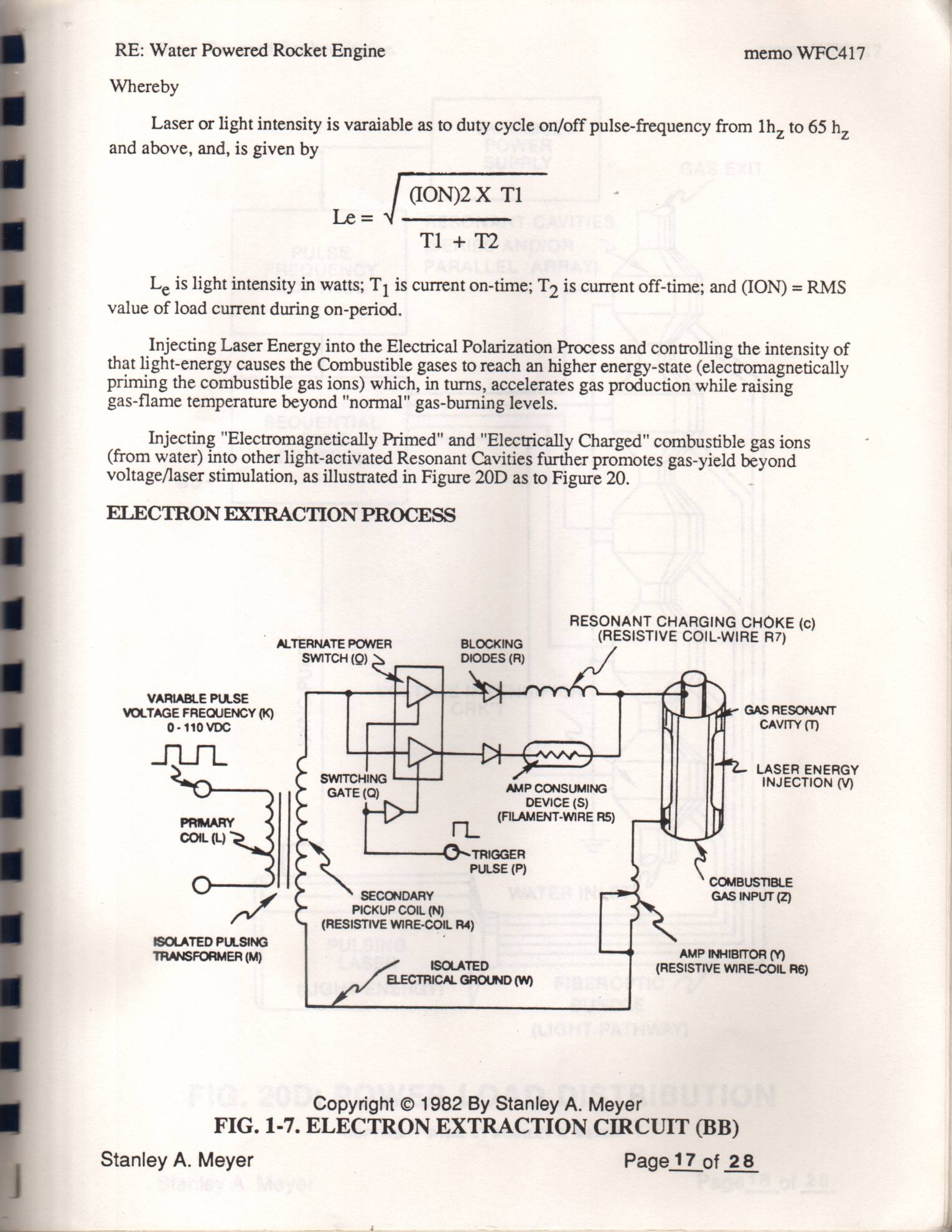
Laser or light intensity is varaiable as to duty cycle on/off pulse-frequency from lh, to 65 h,
and above, and, is given by
Le is light intensity in watts; Tj is current on-time; T3 is current off-time; and (ION) = RMS value of load current during on-period.
Injecting Laser Energy into the Electrical Polarization Process and controlling the intensity of that light-energy causes the Combustible gases to reach an higher energy-state (electromagnetically priming the combustible gas ions) which, in turns, accelerates gas production while raising gas-flame temperature beyond "normal" gas-burning levels.
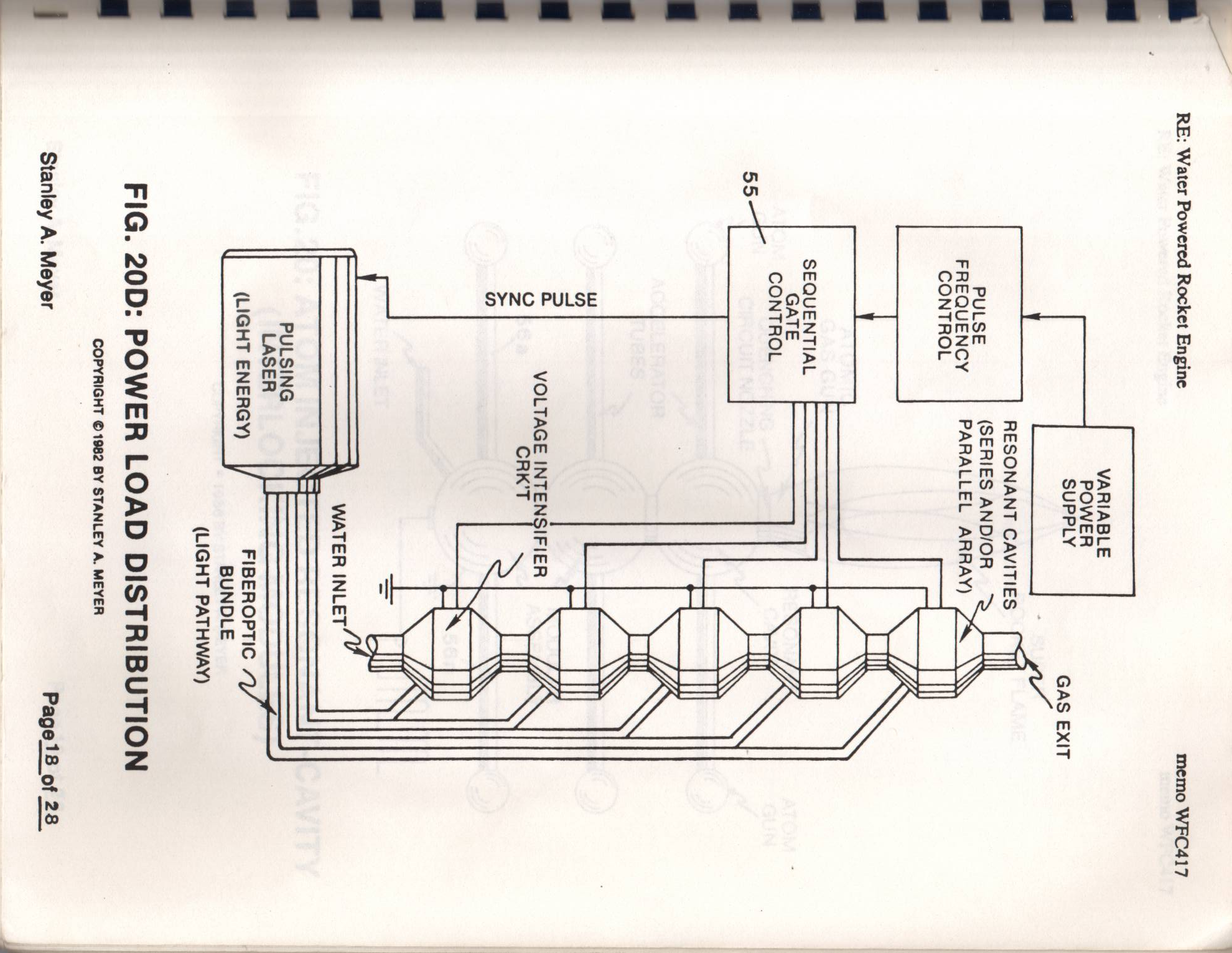
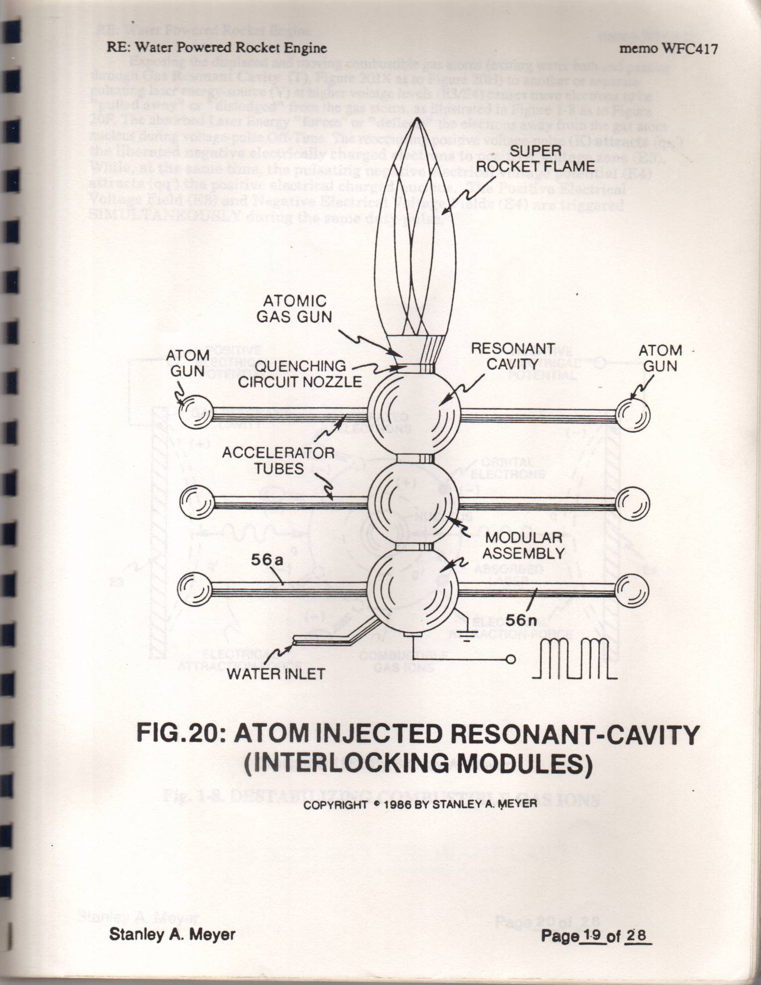
Injecting "Electromagnetically Primed" and "Electrically Charged" combustible gas ions (from water) into other light-activated Resonant Cavities further promotes gas-yield beyond voltage/laser stimulation, as illustrated in Figure 20D as to Figure 20.
ELECTRON EXTRACTION PROCESS
RESONANT CHARGING CHOKE (c)
ALTERNATE R BLOCKING (RESISTIVE COIL-WIRE R7)
SWITCH (Q)
VARIABLE PULSE é )
VOLTAGE FREQUENCY (K) b f ise
LASER ENERGY
Bee conciantic INJECTION (V)
DEVICE (S)
may (FILAMENT-WIRE R5)
COIL (L)
COMBUSTIBLE
GAS INPUT (2)
PICKUP COIL (N)
(RESISTIVE WIRE-COIL R4)
ISOLATED PULSING :
TRANSFORM AMP INHIBITOR (Y)
sah (RESISTIVE WIRE-COIL R6)
Copyright © 1982 By Stanley A. Meyer
FIG. 1-7. ELECTRON EXTRACTION CIRCUIT (BB)
Stanley A. Meyer Page17 of 28
Page 18
RE: Water Powered Rocket Engine memo WFC417
VARIABLE
POWER
SUPPLY GAS EXIT
Bil
(SERIES AND/OR
PARALLEL ARRAY) ~ Ny
PULSE
FREQUENCY
CONTROL
SEQUENTIAL
GATE
CONTROL
VOLTAGE INTENSIFIER
SYNC PULSE
PULSING
LASER
(LIGHT ENERGY)
FIBEROPTIC
BUNDLE
(LIGHT PATHWAY)
FIG. 20D: POWER LOAD DISTRIBUTION
COPYRIGHT © 1982 BY STANLEY A. MEYER
Stanley A. Meyer Page18 of 28.
Page 19
RE: Water Powered Rocket Engine
memo WFC417
. SUPER
ROCKET FLAME
ATOMIC
GAS GUN
RESONANT ATOM
er QUENCHING AVI
CIRCUIT NOZZLE
MODULAR
ASSEMBLY
FIG.20: ATOM INJECTED RESONANT-CAVITY
(INTERLOCKING MODULES)
COPYRIGHT © 1986 BY STANLEY A. MEYER
Stanley A. Meyer
Page 20
RE: Water Powered Rocket Engine memo WFC417
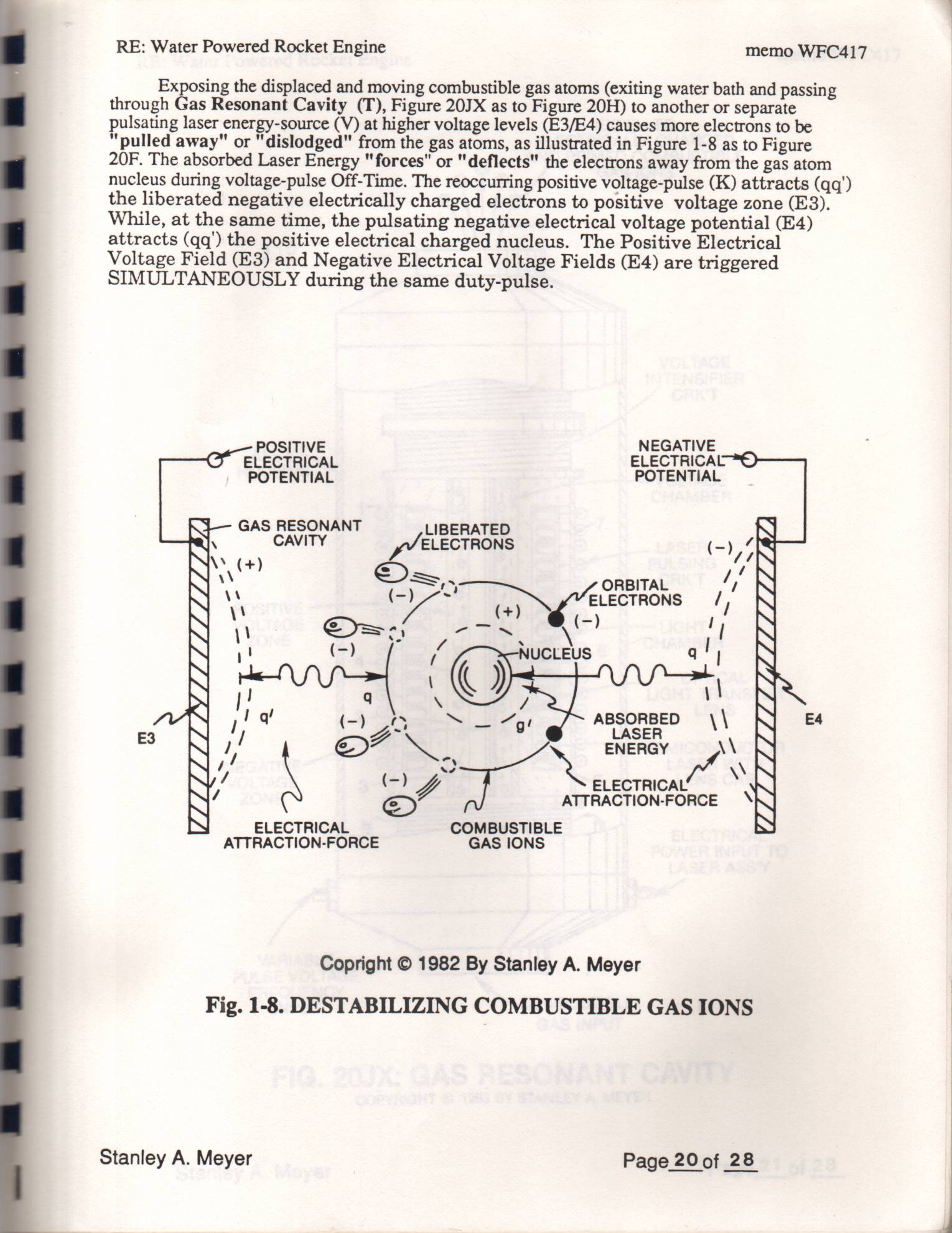
Exposing the displaced and moving combustible gas atoms (exiting water bath and passing through Gas Resonant Cavity (T), Figure 20JX as to Figure 20H) to another or separate pulsating laser energy-source (V) at higher voltage levels (E3/E4) causes more electrons to be “pulled away" or "dislodged" from the gas atoms, as illustrated in Figure 1-8 as to Figure
20F. The absorbed Laser Energy "forces" or "deflects" the electrons away from the gas atom nucleus during voltage-pulse Off-Time. The reoccurring positive voltage-pulse (K) attracts (qq') the liberated negative electrically charged electrons to positive voltage zone (E3). While, at the same time, the pulsating negative electrical voltage potential (E4) attracts (qq') the positive electrical charged nucleus. The Positive Electrical Voltage Field (E3) and Negative Electrical Voltage Fields (E4) are triggered SIMULTANEOUSLY during the same duty-pulse.
NEGATIVE
ELECTRICAL ELECTRICAL
POTENTIAL POTENTIAL
GAS RESONANT LIBERATED
CAVITY ELECTRONS (-),4
= = ORBITAL 4,
os ae a Ng ECTRONS 4,
ABSORBED \\ E4
LASER
ENERGY M
me yal \\
ELECTRICAL COMBUSTIBLE
ATTRACTION-FORCE GAS IONS
Copright © 1982 By Stanley A. Meyer
Fig. 1-8. DESTABILIZING COMBUSTIBLE GAS IONS
Stanley A. Meyer Page 20 of 28
Page 21
RE: Water Powered Rocket Engine memo WFC417
EXPELLED
ELECTRICALLY CHARGED
AND PRIMED COMBUSTIBLE
GAS IONS
VOLTAGE
INTENSIFIER
HOUSING
LASER
PULSING
POSITIVE a) —
VOLTAGE
ZONE
LIGHT
CHAMBER
OPTICAL
LIGHT TRANSFER
LENS
UUW
sae
= SEMICONDUCTOR
NEGATIVE yr |) LASER WITH — nar He LENS CAP
ELECTRICAL
POWER INPUT TO
LASER ASS'Y
VARIABLE
PULSE VOLTAGE
FREQUENCY
INPUT *, COMBUSTIBLE
GAS INPUT
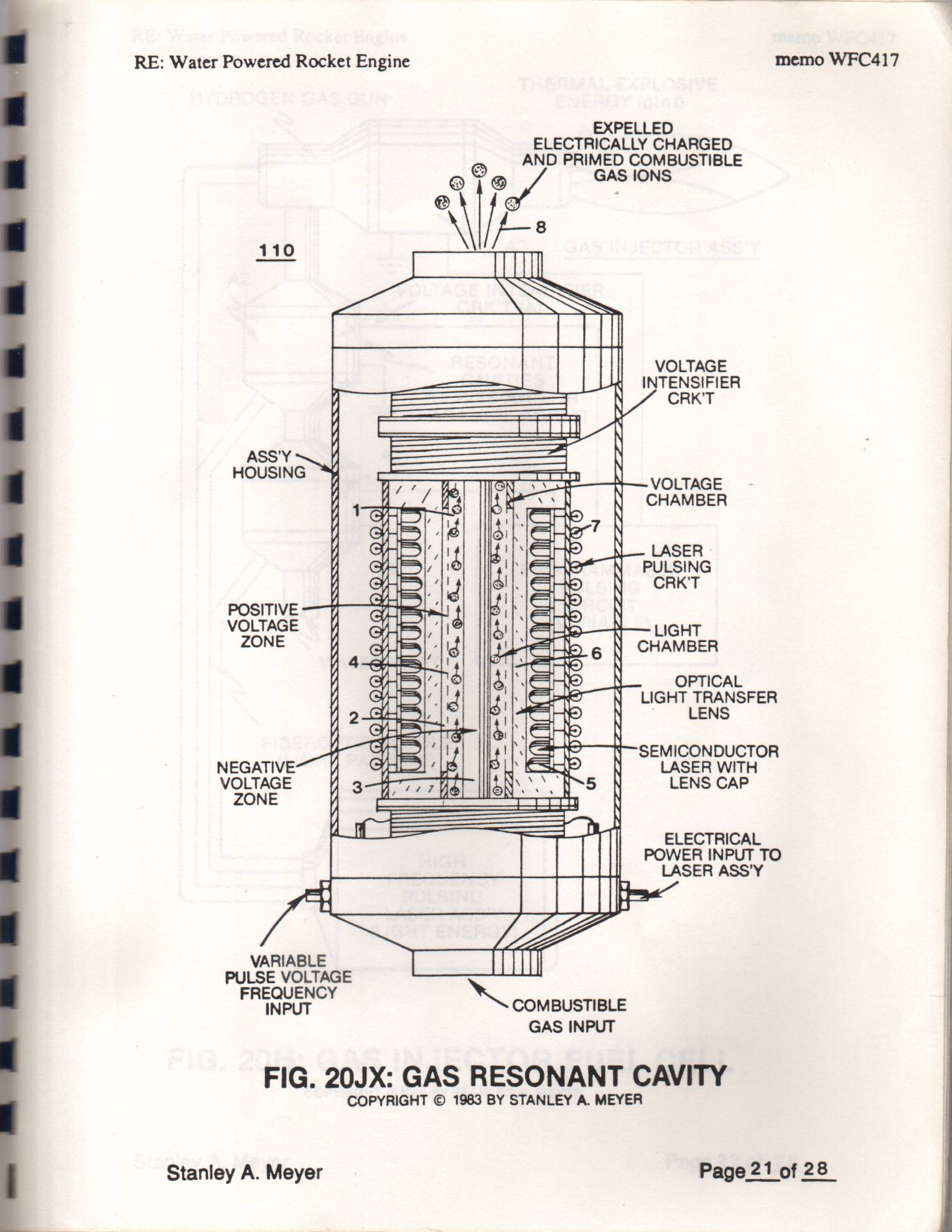
FIG. 20JX: GAS RESONANT CAVITY
COPYRIGHT © 1983 BY STANLEY A. MEYER
Stanley A. Meyer Page 21 of 28
Page 22
‘ez J0zcz obey Joke “y Aeueys
Y3AIW “VW AD INVIS AG £861 LHOIWAdOD
7149 14N4 YOLOSANI SVD -HO2 “Sis
(ADY3N3 LHI)
(AVMHLVd LH5DI7)
SIONNSE OlidOu3gls
LIINI HSLVM
LINDYID
SNISTNd
JIGVWWVYDOud
(AVaYV TATIWdvd
(ju}6) ADYANA NNS SVS N3D5Ou8d0AH 3AISO1dx3 TWWYSHL
LIPOAM Oursur auidug 12x90y posamod Je AA “TY
Page 23
RE: Water Powered Rocket Engine memo WFC417
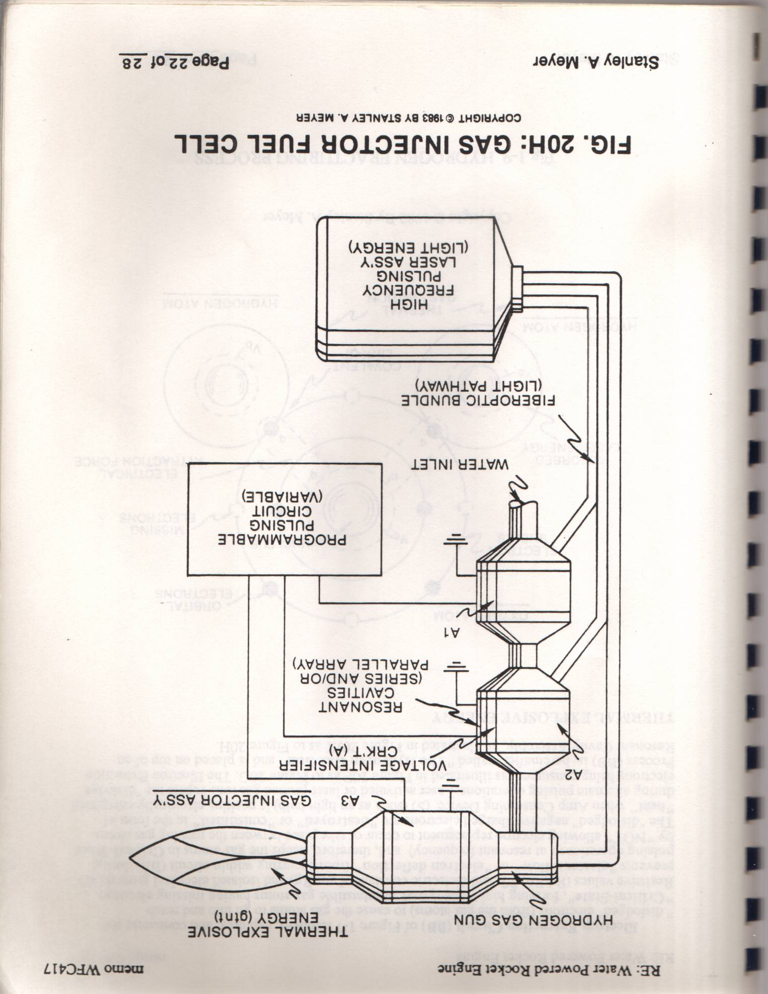
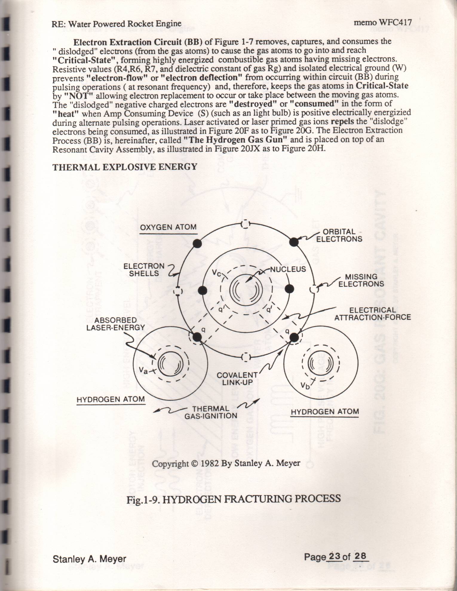
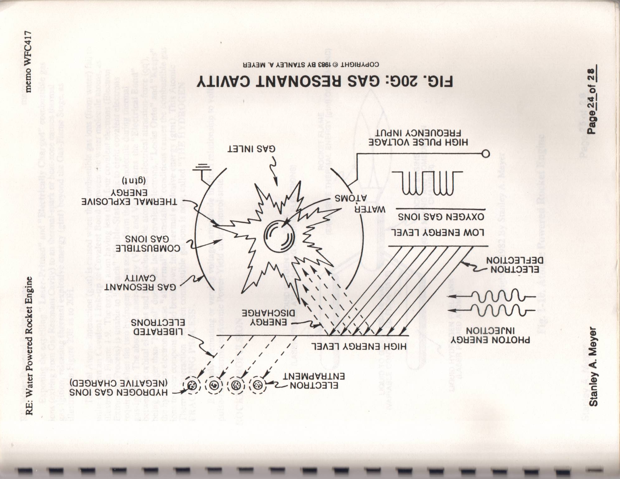
Electron Extraction Circuit (BB) of Figure 1-7 removes, captures, and consumes the " dislodged" electrons (from the gas atoms) to cause the gas atoms to go into and reach "Critical-State", forming highly energized combustible gas atoms having missing electrons. Resistive values (R4,R6, R7, and dielectric constant of gas Rg) and isolated electrical ground (W) prevents "electron-flow" or "electron deflection" from occurring within circuit (BB) during pulsing operations (at resonant frequency) and, therefore, keeps the gas atoms in Critical-State by "NOT" allowing electron replacement to occur or take place between the moving gas atoms. The "dislodged" negative charged electrons are "destroyed" or "consumed" in the form of "heat" when Amp Consuming Device (S) (such as an light bulb) is positive electrically energizied during alternate pulsing operations. Laser activated or laser primed gas ions repels the "dislodge" electrons being consumed, as illustrated in Figure 20F as to Figure 20G. The Electron Extraction Process (BB) is, hereinafter, called "The Hydrogen Gas Gun" and is placed on top of an Resonant Cavity Assembly, as illustrated in Figure 20JX as to Figure 20H.
THERMAL EXPLOSIVE ENERGY
OXYGEN ATOM i aes
ELECTRONS
ELECTRON
ee MISSING
ELECTRONS
ELECTRICAL
ABSORBED ATTRACTION-FORCE
COVALENT
THERMAL az
HYDROGEN ATOM
HYDROGEN ATOM
Copyright © 1982 By Stanley A. Meyer
Fig.1-9. HYDROGEN FRACTURING PROCESS
Stanley A. Meyer Page. 23 of 28
Page 24
memo WFC417
Y3AaW ‘V AD INVLS AG £861 © LHDIHAdOD
ALIAVD LNVWNOSAY SV9D -902 “Sid
1a 1NI SVD ASVIOA AS1Nd HDIH
ASYANS
AAISO1dX3 IWAWHSHL
SNOI SVD NADAXO
SNOI SVD 13A31 ADYSN]A MOT
ALIAVD .
INVNOS3Y SVD
SNOW10313 ADYINS ——2ea \ daivyaan pi” ercaiatl NOILOAENI EN 0 ¢ TaN) 49W3NA HOIH plaaiorercoiseg
SNOL SVD NIDOHGAH ee! \@) \@) @y-e— Nowloaa
Page 24 of 2
Stanley A. Meyer
Page 25
RE: Water Powered Rocket Engine memo WFC417
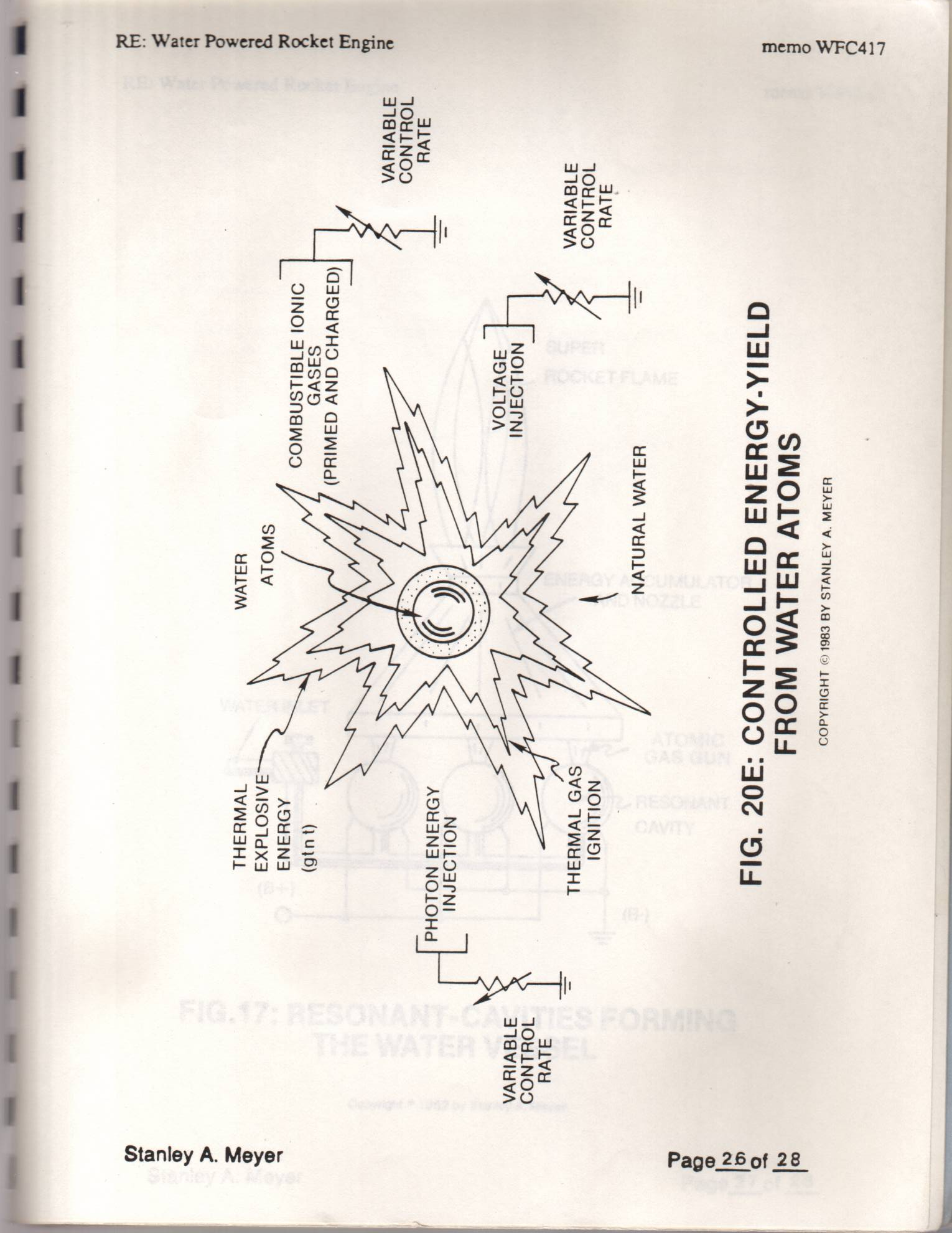
Exposing the expelling " Laser-Primed" and "Electrically Charged" combustible gas ions (exiting from Gas Resonant Cavity) to an thermal-spark or heat-zone causes thermal gas-igition, releasing thermal explosive energy (gtnt) beyond the Gas-Flame Stage, as illustrated in Figure 20E as to 20H.
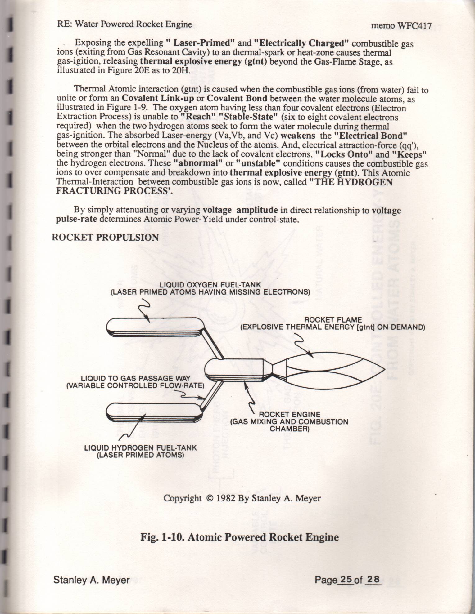
Thermal Atomic interaction (gtnt) is caused when the combustible gas ions (from water) fail to unite or form an Covalent Link-up or Covalent Bond between the water molecule atoms, as illustrated in Figure 1-9. The oxygen atom having less than four covalent electrons (Electron Extraction Process) is unable to "Reach" "Stable-State" (six to eight covalent electrons required) when the two hydrogen atoms seek to form the water molecule during thermal gas-ignition. The absorbed Laser-energy (Va, Vb, and Vc) weakens the "Electrical Bond" between the orbital electrons and the Nucleus of the atoms. And, electrical attraction-force (qq'), being stronger than "Normal" due to the lack of covalent electrons, "Locks Onto" and "Keeps" the hydrogen electrons. These "abnormal" or "unstable" conditions causes the combustible gas ions to over compensate and breakdown into thermal explosive energy (gtnt). This Atomic Thermal-Interaction between combustible gas ions is now, called "THE HYDROGEN
FRACTURING PROCESS'.
By simply attenuating or varying voltage amplitude in direct relationship to voltage ! pulse-rate determines Atomic Power- Yield under control-state. : |
ROCKET PROPULSION
LIQUID OXYGEN FUEL-TANK |
(LASER PRIMED ATOMS HAVING MISSING ELECTRONS) |
ROCKET FLAME
(EXPLOSIVE THERMAL ENERGY [gtnt] ON DEMAND)
LIQUID TO GAS PASSAGE WAY
(VARIABLE CONTROLLED FLOW-RATE)
ROCKET ENGINE
(GAS MIXING AND COMBUSTION
CHAMBER)
LIQUID HYDROGEN FUEL-TANK
(LASER PRIMED ATOMS)
Copyright © 1982 By Stanley A. Meyer
Fig. 1-10. Atomic Powered Rocket Engine
Stanley A. Meyer Page 25 of 28
Page 26
THERMAL
EXPLOSIVE
ENERGY
(gtn t)
WATER
ATOMS
Stanley A. Meyer
COMBUSTIBLE IONIC
GASES
(PRIMED AND CHARGED)
RE: Water Powered Rocket Engine
VARIABLE
CONTROL
RATE
PHOTON ENERGY
INJECTION
VOLTAGE
VARIABLE INJECTION
CONTROL
RATE
VARIABLE
CONTROL
RATE
a THERMAL GAS
IGNITION
NATURAL WATER =
FIG. 20E: CONTROLLED ENERGY-YIELD
FROM WATER ATOMS
COPYRIGHT © 1983 BY STANLEY A. MEYER
memo WFC417
Page 27
RE: Water Powered Rocket Engine memo WFC417
SUPER
\_ ROCKET FLAME
ENERGY ACCUMULATOR
AND NOZZLE
ATOMIC
GAS GUN
RESONANT
CAVITY
FIG.17: RESONANT-CAVITIES FORMING
THE WATER VESSEL
Copyright © 1982 by Stanley A. Meyer
Stanley A. Meyer Page27 of 28
Page 28
RE: Water Powered Rocket Engine memo WFC417
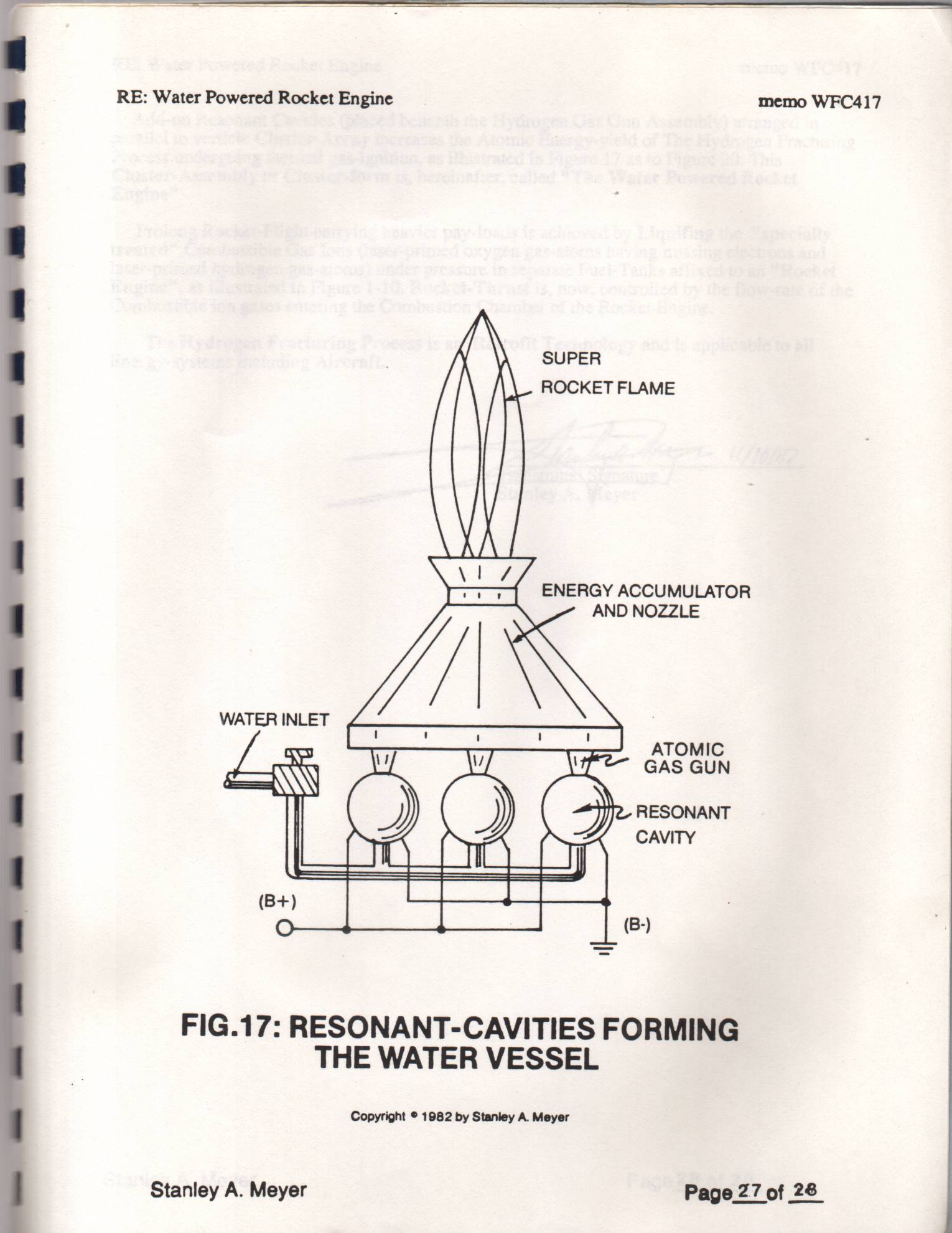
Add-on Resonant Cavities (placed beneath the Hydrogen Gas Gun Assembly) arranged in parallel to verticle Cluster-Array increases the Atomic Energy-yield of The Hydrogen Fracturing Process undergoing thermal gas-ignition, as illustrated in Figure 17 as to Figure 20. This Cluster-Assembly or Cluster-form is, hereinafter, called "The Water Powered Rocket
Prolong Rocket-Flight carrying heavier pay-loads is achieved by Liquifing the "specially treated" Combustible Gas Ions (laser-primed oxygen gas-atoms having missing electrons and laser-primed hydrogen gas-atoms) under pressure in separate Fuel-Tanks affixed to an "Rocket Engine", as illustrated in Figure 1-10. Rocket-Thrust is, now, controlled by the flow-rate of the Combustible ion gases entering the Combustion Chamber of the Rocket Engine.
The Hydrogen Fracturing Process is an Retrofit Technology and is applicable to all Energy-systems including Aircraft.
Stanley A. Meyer Page 28 of 28°
Provenance
- Shelf
- Stan Meyer Publications
- Method
- Optical character recognition, unchecked against the pages
- Source
- Scanned pages of WFC 417