patent · US4650415A
Combustion chamber for heating devices
17 March 1987
Page 1 — bibliographic record
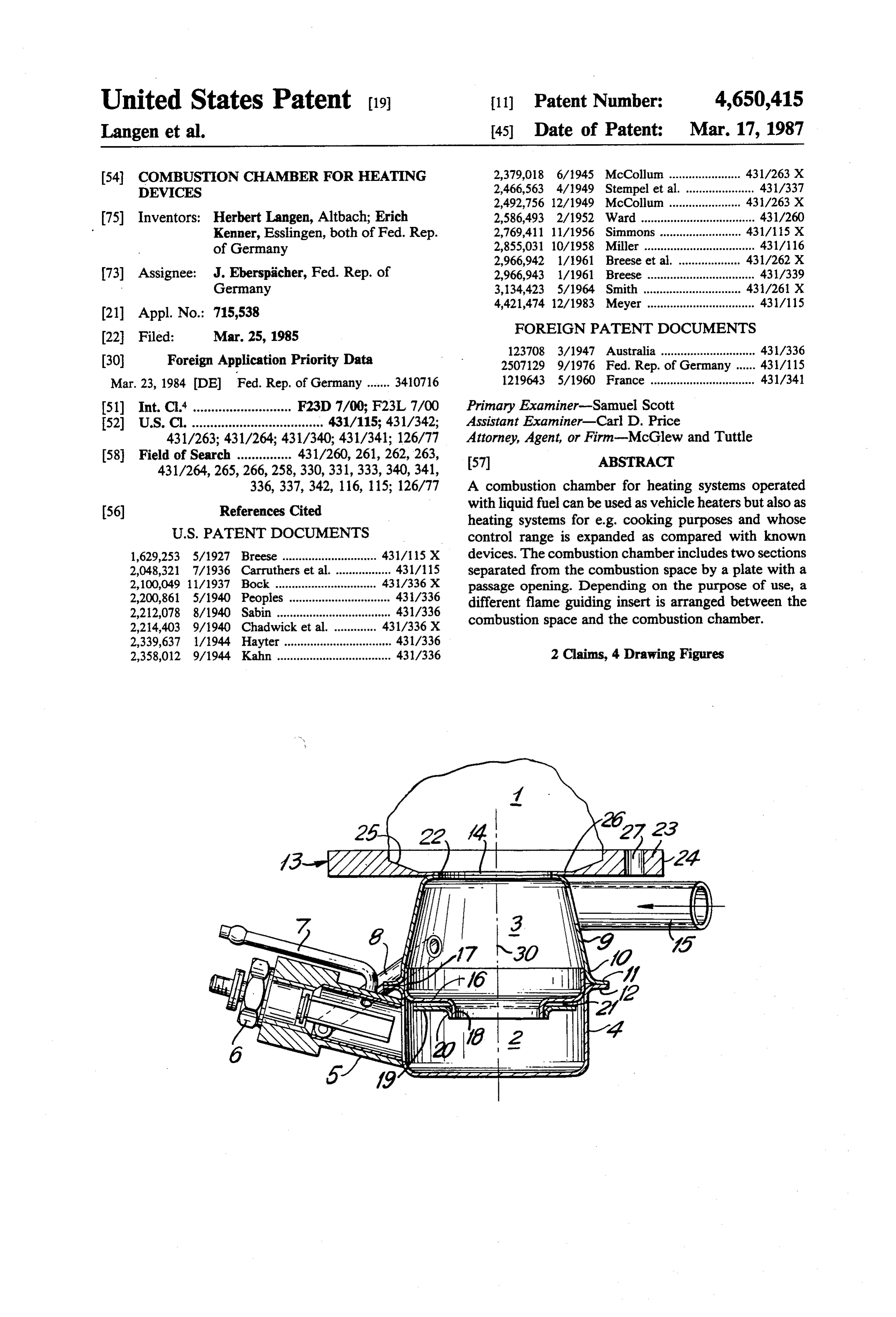
United States Patent (19) 11) Patent Number: 4,650,415 Langen et al. 45 Date of Patent: Mar. 17, 1987 54). COMBUSTION CHAMBER FOR HEATING 2,379,018 6/1945 McCollum ...................... 431/263 X DEVICES 2,466,563 4/1949 Stempel et al. ..................... 431/337 2,492,756 12/1949 McCollum .... ... 43/263 X 75) Inventors: Herbert Langen, Altbach; Erich 2,586,493 2/1952 Ward ................................... 431/260 Kenner, Esslingen, both of Fed. Rep. 2,769,411 11/1956 Simmons .. ... 431/15 X of Germany 2,855,031 10/1958 Miller .................................. 431/16 2,966,942 1/1961 Breese et al. . ... 431/262 X 73) Assignee: J. Eberspicher, Fed. Rep. of 2,966,943 1/1961 Breese .. ... 431/339 Germany 3,134,423 5/1964 Smith .... ... 431/261 X 4,421,474 12/1983 Meyer ................................. 431/115
FOREIGN PATENT DOCUMENTS
123708 3/1947 Australia ............................. 431/336 30 Foreign Application Priority Data 2507129 9/1976 Fed. Rep. of Germany ...... 431/115 Mar. 23, 1984 DE Fed. Rep. of Germany ....... 3410716 1219643 5/1960 France ................................ 431/341 51) Int. C. ........................... F23D 7/00; F23L 7/00 Primary Examiner-Samuel Scott 52 U.S. Cl. .................................... 431/115; 431/342; Assistant Examiner-Carl D. Price 431/263; 431/264; 431/340; 431/341; 126/77 Attorney, Agent, or Firm-McGlew and Tuttle 58 Field of Search ............... 431/260, 261, 262,263, 57 ABSTRACT
336,337,342, 116, 115; 126/77 A combustion chamber for heating systems operated (56) References Cited with liquid fuel can be used as vehicle heaters but also as heating systems for e.g. cooking purposes and whose
1,629,253 5/1927 Breese ............................. 431/15 X devices. The combustion chamber includes two sections 2,048,321 7/1936 Carruthers et al. ................. 431/15 separated from the combustion space by a plate with a 2,100,049 11/1937 Bock .................... ... 43/336X passage opening. Depending on the purpose of use, a 2,200,861 5/1940 Peoples ............................... 43/336 different flame guiding insert is arranged between the 2,212,078 8/1940 Sabin ................................... 431/336 combustion space and the combustion chamber. 2,214,403 9/1940 Chadwicket al. ... 431/336X 2,339,637 1/1944 Hayter ................................. 431/336 2,358,012 9/1944 Kahn ................................... 431/336 2 Claims, 4 Drawing Figures
samara NCAAP comes Tya
Page 2
Drawing sheet — no readable text.
Page 3
Drawing sheet — no readable text.
Page 4
tion. With this design of the combustion chamber ac
COMBUSTION CHAMBER FOR HEATING cording to the invention an arrangement is indicated DEVICES which permits an output regulation over the almost total output range. This results from the fact that both
FIELD AND BACKGROUND OF THE the flame form and the region in which the combustion INVENTION takes place inside the combustion chamber can be var This invention relates in general to combustion de ied. Thus it can be achieved that the combustion takes vices and in particular to a new and useful combustion place only in the second section of the combustion device for a heater or stove. chamber, or in both sections or in the entire combustion The invention relates to a combustion chamber for 10 chamber and that thereby a controllability is obtained. heating devices operated with liquid fuel, having a com To keep the combustion in the second section and bustion space with a correlated first section in which thereby to be able to run the smallest output stage, it has the combustion air supply occurs tangentially, and a been found appropriate to give the diaphragm type further second section, having a pipe with the ignition 15 insert a circular ring-shaped cross-section, the outer means, as well as a connection for a metering pump and edge being bent by about 90 to form an abutment edge for an area for spark plug ventilation. and the inner edge by about 90" in the opposite direc Such combustion chambers are needed for heating tion.
devices which are used as household heating systems, The exact angle measurements depend on the installa e.g. at cooking stations and also for motor independent 20 tion situation.
vehicle heaters. For household heating systems pressure For the transition combustion from the second to the atomizer burners with wattages starting at about 20 kW first section the diameter of the passage opening is of are known. Smaller wattages down to 12 kW are real importance. Appropriately the ratio of the inner diame ized with expensive oil preheating, but substantially ter to the outer diameter of the diaphragm type insert or smaller wattages are not possible. But devices with relatively low output are required when what is in disc 25 phragm is 1:1.2 to 1:4, preferably 1:2. To protect this dia type insert against overheating, according to volved is e.g. a single cooking station. In vehicle heaters the known devices can be regulated for burner outputs further aspect of the invention, there is arranged below between "Full” (“High”) and "Off", in some vehicle the insert an anti-overheating disc which has a circular ring-shaped cross-section and is bent at its inner edge by heaters between "Full' and about "one quarter burner output'. A greater control range is not known at pres 30 about 90 to form an abutment flange. The anti-over ent, although it would be desirable for comfort and also heating flange disc is adapted to apply by its bent abutment against the bent inner edge of the diaphragm type so as to have to ignite only once in a heating interval, while in the known heating systems with thermostat insert, the disc being spaced from the insert and having control the control occurs by On/Off switching; this a somewhat smaller outside diameter than the inner leads to increased current consumption from the vehicle 35 diameter of the second section. battery and may lead to premature discharge of the For the form of the hot combustion gases or of the battery, the more so as such heaters are operated prefer flame passing from the second section via the first sec ably at standstill, that is, with the engine turned off. tion into the combustion chamber, the matching of the In such heating devices the fuel supply occurs by exit openings is essential. A further feature of the inven means of a pulse-controlled metering pump. In this case tion therefore is that the side of the plate toward the it is possible by means of a frequency regulator, through combustion space has a surface ascending from about a thermostat, to regulate the output of the heating the inner edge to a flange forming horizontal section at equipment to a certain extent by varying the pump the outer edge. Thereby a flame form from dish-shaped frequency, as for instance in a range of from 1:4 to about to ray-shaped can be adjusted. Advantageously, the 1:8. 45 angle of inclination of the ascending surface is between SUMMARY OF THE INVENTION 15' and 90', preferably 20.
For the connection of the combustion chamber wall
The invention provides a combustion chamber, by and possibly also of a heat component it is appropriate the construction and design of which its output range to provide contiguous to the ascending surface of the becomes variable, so that the control range of the heat 50 plate on both sides a plane section, and according to a ing equipment is substantially expanded. At the same variant, the plate is formed in its plane inner section to time the combustion space is to be suitable for installa receive a flame guiding insert. According to the inven tion either with the axis vertical or with the axis hori
Zontal. tion, the ascending surface may be concave, this leading The combustion chamber includes a first section sep to55 an especially good contact of the combustion gases or arated from the combustion space by a plate having a atethe of flame. The further sub-claims indicate appropri realizations of the flame guiding insert. This flame central passage opening and which comprises a trun guiding insert contributes essentially to the flame form. cated cone-shaped portion with a cylindrical prolonga tion with the tapered part of the truncated cone-shaped Accordingly it is an object of the invention to pro portion pointing toward the combustion space and vide an improved combustion device which includes a being provided with a pipe for tangential combustion plate having an opening which communicates with the air supply. A second section is pot-shaped and is con top of a combustion housing having an upper portion nected at its open side with the first section and has a with a tangential combustion air inlet and a lower por lateral pipe. The lateral pipe is designed to receive the tion for ignition of the burnable products which is con spark plug ventilation line which extends from the first 65 nected with a lateral pipe containing a sparkplug igniter section to the lateral pipe of the second section. An and a fuel supply into the pipe along with a recirculat internal diaphragm type insert is arranged in the region ing passage extending from the upper combustion pas of the connection of the second section to the first sec sage back to the ignition and fuel supply plate which
Page 5
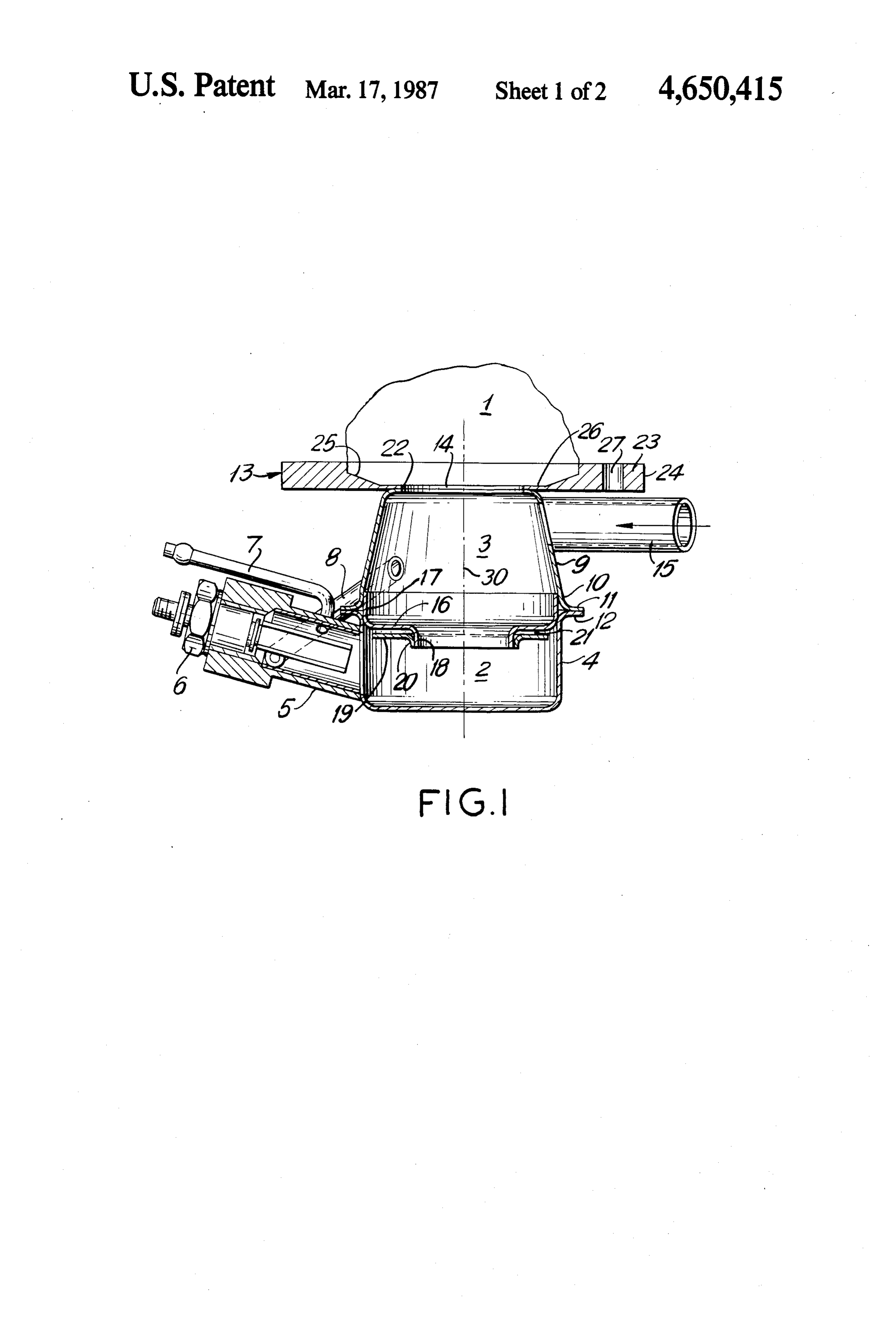
connects into the ignition portion of the combustion bustion space 1, is a plate 13 with a central passage chamber. opening 14. Tangentially to the second section 3 a com A further object of the invention is to provide an bustion air supply pipe 15 is arranged. In the region of improved device which may function as a heater or the connection of the first section 2 to the second sec cooker. 5 tion 3 a diaphragm type insert or disc 16 is arranged, A further object of the invention is to provide a com which has an abutting edge 17 bent toward the combus bustion device which is simple in design, rugged in tion space 1 and an edge 18 bent in the opposite direc construction and economical to manufacture. tion and which serves to keep the combustion in the first The various features of novelty which characterize section 2. Spaced from this diaphragm type insert 16 an the invention are pointed out with particularity in the O overheating protection disc 19 with an abutting flange claims annexed to and forming a part of this disclosure. 20 is arranged in such a way that this disc 19 applies by For a better understanding of the invention, its operat its flange 20 against the outside of the inner edge 18 of insert 16 and has an air slit 21 opposite the horizontal ing advantages and specific objects attained by its uses, section reference is made to the accompanying drawings and of insert 16. The outside diameter of disc 19 does descriptive matter in which preferred embodiments of 15 not abur on the cylindrical prolongation 4 of section 2. the invention are illustrated. Thereby overheating protection is achieved. On its side toward the combustion space 1, plate 13
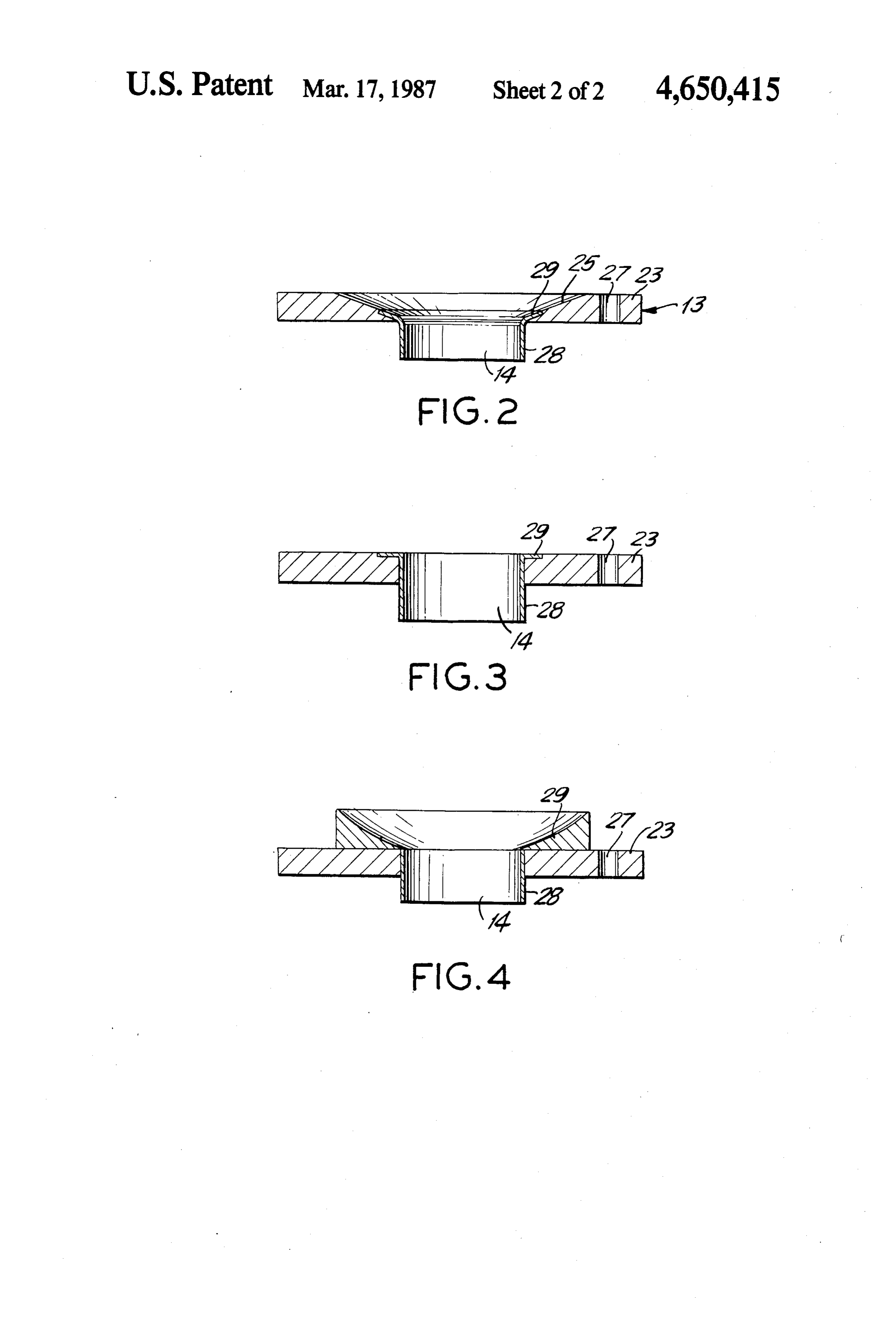
BRIEF DESCRIPTION OF THE DRAWINGS has an oblique surface 25 ascending from about the In the drawings: inner edge 22 to a flange forming horizontal section 23 FIG. 1 is a sectional view of a combustion device 20 at the outer edge 24. The slanting surface 25 may be constructed in accordance with the invention; concave and furthermore, at the inner edge 22, a like FIG. 2 is a sectional view similar to FIG. 1 showing wise plane surface 26 may be formed. It serves in partic a modified arrangement in accordance with another ular for receiving a flame guiding insert 29 with inte embodiment of the invention; and grally formed abutting flange 26. Depending on the FIGS. 3 and 4 are views similar to FIG. 2 of still 25 desired flame form, the flame guiding insert 28 or 29 further embodiments of the invention. may be cylindrical, in the form of a hollow truncated cone or like a nozzle. Bores 27 in plate 13 serve for the
DESCRIPTION OF THE PREFERRED connection of the combusion space wall or respectively EMBODIMENTS of a heat jacket and the exhaust gas discharge elements. Referring to the drawings in particular the invention 30 The controllability of the combustion chamber re embodied therein comprises a heating device which sults physically by a change of the air excess number, includes a plate 13 having an opening providing a com i.e. the air excess is changed. With the arrangement bustion area over the opening designated 1. A housing according to the invention this is possible at constant below the plate has a combustion products whirling combustion air throughput. This results from the fact upper portion 3 connected to the opening of the plate 35 that the first section 2 of the combustion chamber is and a lower ignition combustion chamber 2 below the designed as an ignition and small combustion space and upper portion. A dividing wall is formed between the the second section 3 acts as whirl or twist generating upper and lower portions of the combustion chambers 2 antechamber with a swirl zone. The fuel is supplied via and 3 and has a central gas passage therebetween which the ignition element 6 to the first section 2, namely via is formed by their flanged interengagement. the laterally arranged pipe 5. The combustion air is Ignition means includes a spark plug 6 contained in supplied via the tangential combustion air inlet 15 ar the lateral pipe 5 which connects into the ignition and ranged at the second section 3, and between the second small combustion space 2. The liquid fuel is supplied section 3 and pipe 5there exists as connection the spark through a fuel line 7 into the pipe 5. Combustion air plug ventilation 8, so that the air required for ignition which enters through an inlet 15 is whirled around in 45 and combustion is supplied.
the combusion chamber space 3 and a portion of the In the interior of section 3, in a swirl zone 30, the gases are circulated back through a spark plug vent 8 combustion air entering the second section 3 tangen which connects into the lateral pipe of around the spark tially forms eddys, against wall 9 of section3 it forms an plug 6. abutting boundary layer which constitutes a radiation In FIG. 1 is shown the combustion chamber consist 50 protection, so that both cooling out and the formation ing of a combustion space 1 with a first section 2 and a of depositions of unburned particles is prevented. Via second section 3. Not shown is the combustion space the spark plug ventilation 8 combustion air gets into the wall as well as means for exhaust gas removal and the antechamber pipe 5, so that a combustion takes place. structural parts which are not part of the invention. In Additional air required for combustion in the first sec the embodiment the first section 2 of the combustion 55 tion 2 is sucked off the second section 3, so that at small chamber is pot-shaped and comprises at its jacket, that est output the combustion takes place in the first section is, at its cylindrical prolongation, a lateral pipe 5 for 2. Thereby a heating also of the combustion air in the connection of the spark plug 6. The fuel is supplied into second section 3 occurs and due to the design according the pipe 5 via the connection 7. The fuel may be selec to the invention the hot combustion gas or hot air gets tively diesel fuel or gasoline. The air required to initiate into the combustion space 1 and can be taken off at the combustion is supplied via the spark plug ventilation 8. limiting wall thereof for space or area heating, e.g. for This ventilation occurs via a line between the lateral the heating of a hotplate (cooling plate). Upon variation pipe 5 and the second section 3. of the fuel quantity, the combustion advances ever far The second section 3 of the combustion chamber ther into the second section 3 and finally takes place includes a truncated cone-shaped portion 9 followed by 65 there, the flame being able to extend into the combus a cylindrical section 10 and is connected with the first tion space 1 in order thus to reach the maximum output. section 2 by a flange union 11/12. Contiguous to the By the configuration of the plate 13 and the matching section of smaller diameter of part 9, toward the com of the outlet openings or respectively the geometry of
Page 6
the flame guiding insert 28 or 29, the shape of the flame lower ignition combustion chamber portion and into or of the combustion gas emerging into combustion said combustion products whirling upper portion, a space 1 can be determined. Thus, in the case of a house venting pipe extending from said combustion products hold heating system with cooking possibility a short whirling upper portion downwardly into said ignition construction with dish-shaped, flat, and hence area supply pipe, and a combustion air inlet duct connected heating action is desired, whereas for use, e.g. as vehicle tangentially into said combustion products whirling heating equipment a ray shaped admission is desired. upper portion near said plate, combustion gases being It is of advantage further that the arrangement ac formed in said combustion products whirling upper cording to the invention can be operated both with portion exiting through the central opening of said plate vertical and with horizontal axis. The regulation can be 10 and into said combustion area; said housing being effected by varying the fuel quantity stepwise or slid formed of two pot-shaped members with one member ingly, the fuel transport occurs through a known meter being inverted in respect to the other, each of said mem ing pump and hence is largely independent of viscosity.
An additional regulation to smallest outputs is possible bersing having flanges that abut each other, said disc divid said portions having an outer diameter engaged by reducing the combustion air quantity, so that in all a 15 against an inside of said members and an inner diameter wide control range exists. defining said central gas passage; said disc including an While specific embodiments of the invention have inner diameter with an inner edge extending into said been shown and described in detail to illustrate the application of the principles of the invention, it will be lower having ignition combustion chamber portion, said disc an outer abutting edge at said outer diameter understood that the invention may be embodied other 20 extending into said combustion products whirling upper wise without departing from such principles. portion and over said abutting flanges of said pot What is claimed is:
1. A low capacity variable output heating device for shaped members, said edges of said disc extending at vehicles and households comprising a plate having a aboutcentral 90 to an axis of said disc which extends through central opening, means defining a combustion area on 25 said axially gas passage, said opening of said plate being aligned with said axis of said central gas passage, one side of said plate communicating with the opening, a housing on an opposite side of said plate having an and and an overheating wall connected to said inner edge upper end with a combustion product whirling upper extending radially outwardly thereof in said lower portion connected to the opening of said plate, and a ignition combustion chamber portion, said wall being lower ignition combustion chamber portion below said 30 spaced from said disc and having a central opening upper portion, a dividing disc between said combustion through which said central gas passage of said disc products whirling upper portion and said lower ignition passes, said wall having an outer diameter which is combustion chamber portion, said disc having a central smaller than said outer diameter of said disc. gas passage therethrough between said upper and lower 2. A device according to claim 1, wherein said pot portions, ingition and fuel supply pipes extending later 35 shaped member forming said upper chamber portion is ally into said lower ignition combustion chamber por in the form of a truncated cone having a smaller diame tion, ignition means in said ignition supply pipe, a liquid ter at said central opening of said plate and a larger fuel supply directed into said fuel supply pipe and ignit diameter at said disc.
ing therein and said ignited fuel supply flowing into said
Provenance
- Collection
- Patents citing this work
- Current assignee
- Eberspaecher Climate Control Systems GmbH and Co KG
- Original assignee
- J Eberspaecher GmbH and Co KG
- Pages
- 6
- Method
- pdftotext (the PDF's own text layer) + pdftoppm 300dpi page scans
- Patent office record
- patents.google.com →
- Source
- Google Patents citing-documents table
- Inventors
- Herbert Langen; Erich Kenner; J Eberspaecher GmbH and Co KG
- Published
- 1987-03-17
- Transcribed from
- patentimages.storage.googleapis.com →