patent · US2966943
Electric ignition assembly for liquid fuel burners
3 January 1961
Page 1
Drawing sheet — no readable text.
Page 2
Drawing sheet — no readable text.
Page 3
United States Patent Office Patented Jan. 3, 1961
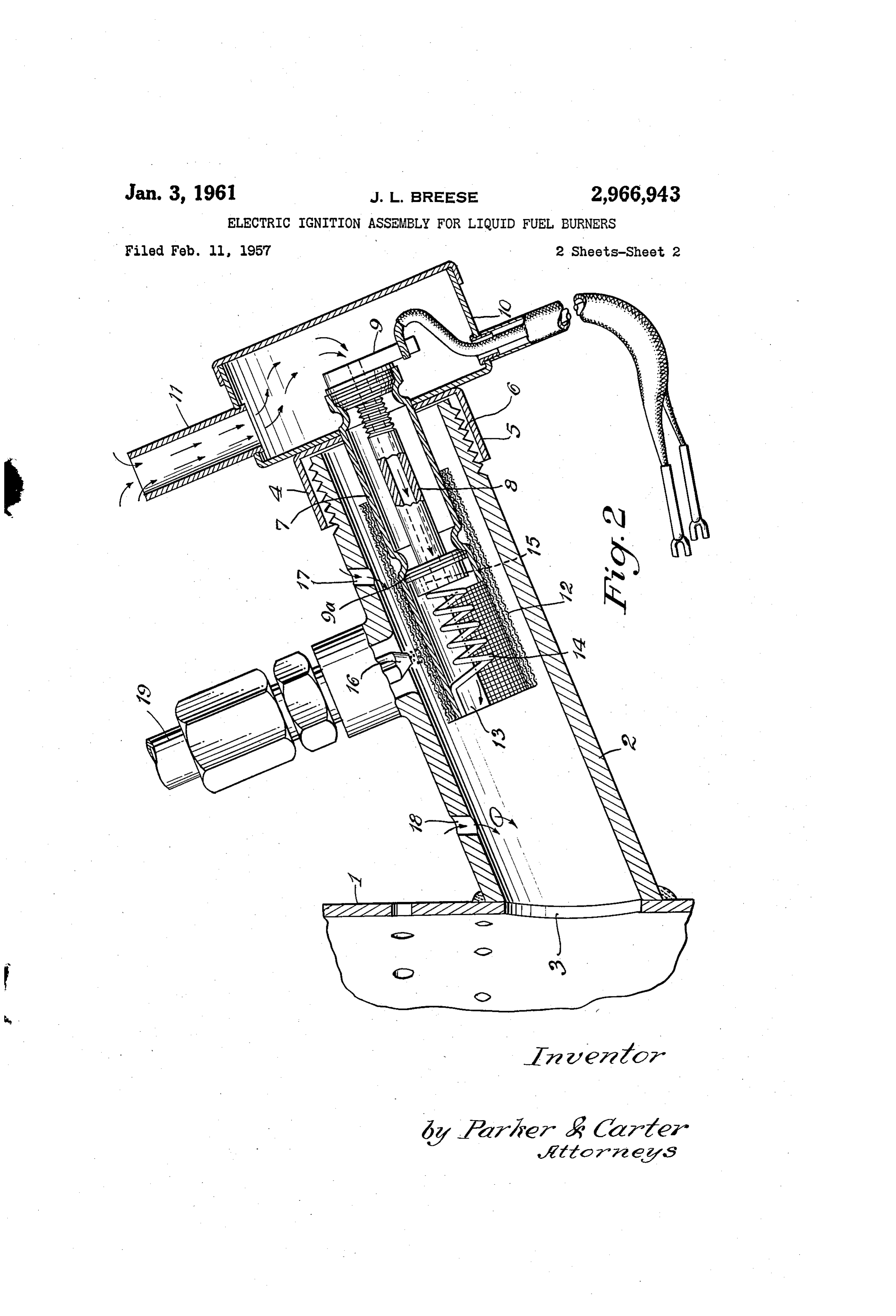
exterior air from a generally cylindrical chamber 10 to the interior of the ignitor. Chamber 10 may be defined by a 2,966,943 closed cylinder on the end of cap 4. An air inlet 11 supplies air to the chamber 10.
ELECTRIC IGNITIONASSEMBLY FOR LIQUID A generally cylindrical gasifier 12 is affixed to the FUEL BURNERS support 7. The gasifier 12 is preferably formed from James L. Breese,to Santa assignments, Fe,Company
Controls N. Mex,ofassignor, mesne three
super-imposed wraps of wire mesh screen. The lower end of the gasifier 12 is affixed to an extension 13
Park, Ill., a corporation of Delaware from the support 7. The upper end of the gasifier 12 is O supported on the body of the support proper. The ex
Filed Feb. 11, 1957, Ser. No. 639,268 tension 13 may be formed as a partly cylindrical mem 3 Claims. (CI. 158-91) ber extending from the body of the cylindrical support 7. A resistance heating element. 14 has one end affixed to the extension 13 and the other end is supplied with
This invention is directed to an improved electrical igni 5 electrical energy through any suitable lead (not shown). tion assembly for hydroxylating pot-type liquid fuel-type The lead may, for example, be brought through the burners. A major purpose of the present invention is spacer 9a for connection to the inner end 15 of the the provision of an improved electrical ignition assembly heating element 14. The electrical connections do not which resists the formation of carbon-like tar on a resist form part of the present invention and for this reason, ance heating element in this type of burner ignition as 20 they are not shown in the drawing. The arrangement sembly. shown permits a variety of electrical connections which Another purpose of the present invention is the provi will be known to those skilled in the art. sion of an improved ignition assembly which generates A fuel inlet nozzle 16 is mounted on the upper por a balanced mixture of combustible gas for ignition. 25 tion of the tube 2 and is adapted to supply liquid fuel Another purpose of the present invention is the provi from a conduit 19 and source (not shown) to the gasifier 12. The nozzle 16 directs liquid fuel in the form of a sion of improved electrical ignition means for pot-type liquid fuel burners which is so formed as to allow the jet stream against the gasifier 12. It should be noted location of a gasifying device at a location remote from that the extension 13 is opposed to the nozzle 16 so as the base of the burner pot. to prevent a direct passage of fuel through the heating Another purpose of the present invention is the provi 30 element. 14. The extension 13 acts to divert fuel sprayed sion of an improved burner pot electrical ignition as on to the gasifier in a generally circumferentially extend sembly that may be readily serviced and which also ing direction around the gasifier, thus protecting the heat provides for lighting the burner manually in the event ing element 14 from direct exposure to the fuel stream. of a power failure. An air inlet is formed in the tube 2 as at 17. The air Another purpose of the present invention is to pro 35 inlet 17 may take, the form of several holes located at vide a combined liquid fuel delivery and electric ignition various positions in the upper portion of the tube 2 be assembly for use with hydroxylating pot-type. liquid fuel tween the nozzle 16 and the end cap 4. If desired, one burners, which can be used as the fuel supply of liquid or more additional air inlets 18 may be formed in the fuel to the interior of the pot, both at the time of ignition 40 tube 2 at a position between the burner pot 1 and the and at all subsequent stages of combustion. nozzle. 16.
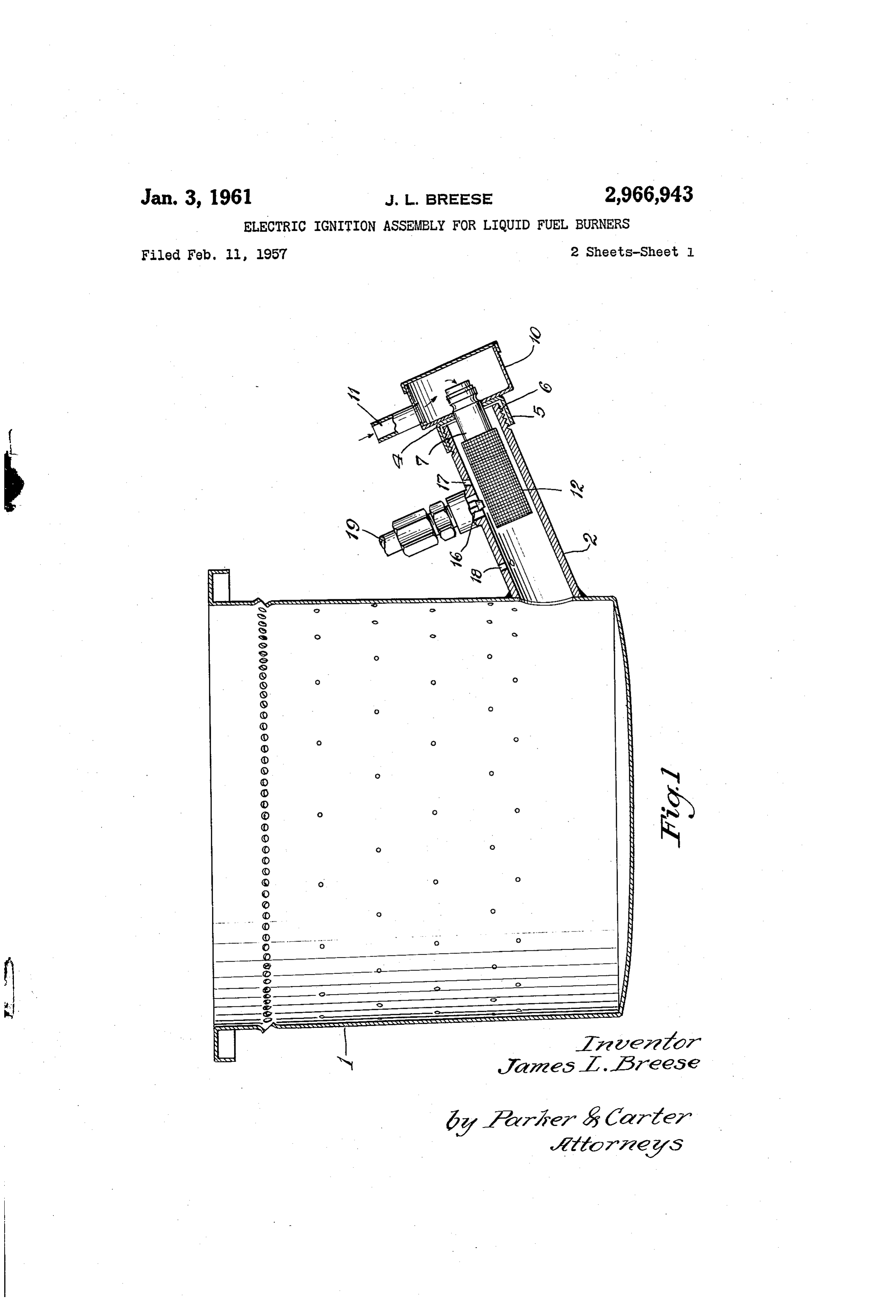
Other purposes will appear in the ensuing specification. Whereas. I have shown and described the operation and claims. of my invention, I wish it to be understood that this Referring generally now to the drawings: showing and description thereof should be taken in an Figure 1 is a side elevational view of the improved illustrative or diagrammatic sense only. There are many burner pot and ignition assembly constituting the present 45 modifications to the invention which will fall within invention; and the scope and spirit of the invention and which will be Figure 2 is an enlarged detail view in section of the apparent to those skilled in the art. The illustration and improved ignition assembly constituting the present in description of the invention should be taken in an il vention. lustrative or diagrammatic sense only and not in any Like elements are designated by like characters 50 limiting sense. The scope of the invention should be throughout the specification and drawings. limited only by the scope of the hereinafter appended Referring specifically now to the drawing and in the claims.
first instance to Fig. 1, 1 designates a more or less con The use and operation of my invention is as follows: I illustrate an electrical ignition assembly for hy ventional pot-type liquid fuel burner It may have a droxylating plurality of vertically spaced rows of primary and sec 55 liquid fuel pot-type burners. The assembly ondary air inlet apertures in the wall thereof as is well is so formed that the gasifier 12 is located at a remote known to the art. According to the present invention, which,position with respect to the base of the burner pot an ignition tube 2 is affixed to the wall of the burner during use of the pot, may contain a body of pot as by welding and communicates through an aperture fuel. The gasifier 12 is positioned upwardly and away 3 in the pot with the interior of the burner pot. It 60 from this body of fuel in the base of the burner pot. This tends to eliminate the carbon and coking condi should be noted that the tube 2 is inclined to the horizon tal. tion that exists in a wick and heating element when The Outer end of the tube is closed by a cap 4 that pot.the ignitor dips into the fuel pool at the base of a burner fits over the end of the tube and has a rim 5 embracing the outer wall of the tube. The outer wall of the tube 65 When ignition is desired, resistance heating element may be Screw threaded as at 6 so as to provide a passage the14 is energized and a jet stream of oil is delivered against way for exterior air into the interior of the tube in re gasifier 12. Air for combustion is supplied through Sponse to a draft imposed on the burner pot. Positioned the tube 2 and towards the burner pot 1, both on the in centrally of the end of cap 4 is a support 7 which may side of the gasifier 12 and the outside thereof. Air is be cylindrically formed. A hollow tube 8 is positioped 70 Supplied through the tube 8 and through the interior centrally of the support 7 and is mounted thereon as by of the gasifier. At the same time air is supplied along spacers 9 and 9a. The hollow tube 8 serves to conduct the exterior of the gasifier from the inlet 17 and from
Page 4
the spaces between end cap 4 and the outer end of the I claim:
tube 2, if desired. This tends to form a gas mixture 1. In a combined liquid fuel delivery and electric igni that is too rich for ready ignition on that side of the tion assembly adapted for use with hydroxylating pot gasifier adjacent the nozzle and too lean on the interior type liquid fuel burners, a downwardly inclined tube hav of the coil. Somewhere between these extremes there ing an open lower end, a cylindrical pervious vaporiz is a place in which the gas air mixture is perfect for low ing screen element spaced in said tube above said open temperature ignition. lower end, supporting means for the screen element in When ignition is initiated the flame is directed down cluding a tubular structure extending along the axis of wardly into the burner pot. Any excess fuel from the the tube from the outer end of the tube, an electric nozzle 16 runs down the tube 2 into the pot where it is O heating means spaced within said screen element and vaporized during the combustion process. The same means for energizing it for and thereby increasing the assembly may be employed for delivering fuel to the temperature adjacent said screen element, a liquid fuel pot both during ignition and during normal combustion. nozzle positioned on the side of said tube and formed and After ignition and when the combustion process takes adapted to direct a jet of liquid fuel into the interior place within the burner pot, the nozzle 16 may continue of said tube and against the exterior of said vaporizing to deliver fuel against the gasifier 12 from whence it screen element, a shield means interposed between the proceeds to the base of the burner pot. Thus the noz electric heating means and the liquid fuel nozzle, an axial zle 6, with suitable flow control means, not herein air inlet duct positioned to deliver air to the space sur shown, may be employed to supply all the liquid fuel rounded by the vaporizing screen at a zone adjacent the necessary to maintain combustion within the pot at all 20 electric heating means, and a partial closure for the up stages, from ignition to high fire. per end of the tube formed and adapted to permit air By using three wraps of screen wire for the gasifier I leakage into the interior of the tube. w provide an optimum amount of screen mesh for the 2. The structure of claim 1 further characterized in gasification of the fuel. that said shield means shields the electric heating means By using the jet stream of oil against the screen mesh 25 from impingement of the fuel jet, while permitting such gasifier the resistance heating element 14 can operate at jet to contact the vaporizing screen element. or near the theoretical ignition temperature of a dry gas 3. The structure of claim 2 further characterized by which is several hundred degrees lower than the soften a plurality of air inlet apertures in said tube generally ing temperature of ordinary Nichrome coils. Thus with adjacent the ends of said screen. this type of ignition ordinary changes in line voltages 30 will hold the ignitor coil safely between the lowest igni References Cited in the file of this patent tion temperature and the highest melting temperature of the coil. UNITED STATES PATENTS In the event power fails, ignition of the pot may be 1,887,730 Macrae et al. ----------- Nov. 15, 1932 initiated manually by merely removing the cap 4 from 35 1903,364 Grant et al. ----------- Apr. 3, 1933 the end of tube 2, initiating the jet stream of oil and 2,286,854 Holthouse ------------ June 16, 1942 lighting the same with a lighted wad of paper which 2,418,882 Holthouse ------------- Apr. 15, 1947 may be dropped into the tube 2. The end cap 4 and 2,421,370 Budlane ---------------- June 3, 1947 ignition assembly may then again be placed over the 2,481,631 Tramontini------------ Sept. 13, 1949 end of the tube 2 after combustion is thus initiated. The 40 2,492,756 McCollum ------------ Dec. 27, 1949 tube 2 is threaded as at 6 to receive a cap where electric 2,593,166 Meyer --------------- Dec. 15, 1952 ignition is not desired and normal ignition with a torch 2,685,917 Perry ---------------- Aug. 10, 1954 is to be used (not shown in the drawing). 2,693.913 Resek et al. ------------ Nov. 9, 1954 The jet stream delivered against the gasifier provides 2,712,352 Manor et al. ------------- July 5, 1955 instant ignition for the burner and this tends to provide 45 2,729,282 Lennox ----------------- Jan. 3, 1956 a faster burner warmup.
Provenance
- Collection
- Cited prior art
- Original PDF
- patentimages.storage.googleapis.com →
- Filed
- 1957-02-11
- Pages
- 4
- Method
- pdftotext (the PDF's own text layer) + pdftoppm 300dpi page scans
- Source
- Google Patents bibliographic record
- Granted
- 1961-01-03
- Inventors
- James L Breese; Controls Company of America
- Transcribed from
- patentimages.storage.googleapis.com →