patent · US2492756
Fuel vaporizing and combustion apparatus
27 December 1949
Page 1
Drawing sheet — no readable text.
Page 2
Drawing sheet — no readable text.
Page 3
Drawing sheet — no readable text.
Page 4
Patented Dec. 27, 1949 2,492,756
U2, WAPORZANG AND COM BUS ON
APPARATUS
Henry J. De N. McCollum, deceased, late of Chi cago, Ill., by Thelma McCollum, executrix, Chi cago, Ill., assignor to Stewart-Warner Corpo ration, Chicago, Ill., a corporation of Virginia
Application January 26, 1946, Serial No. 643,598
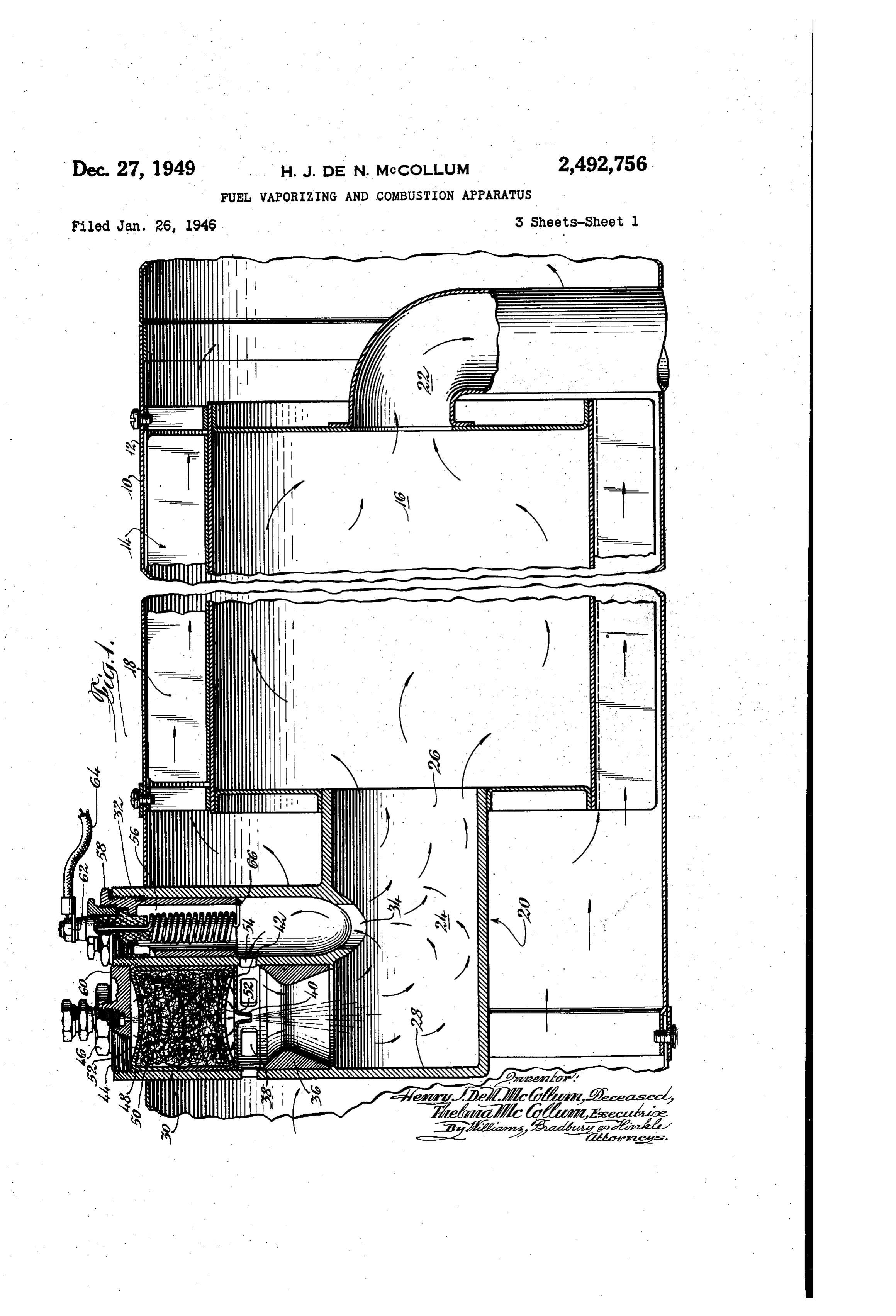
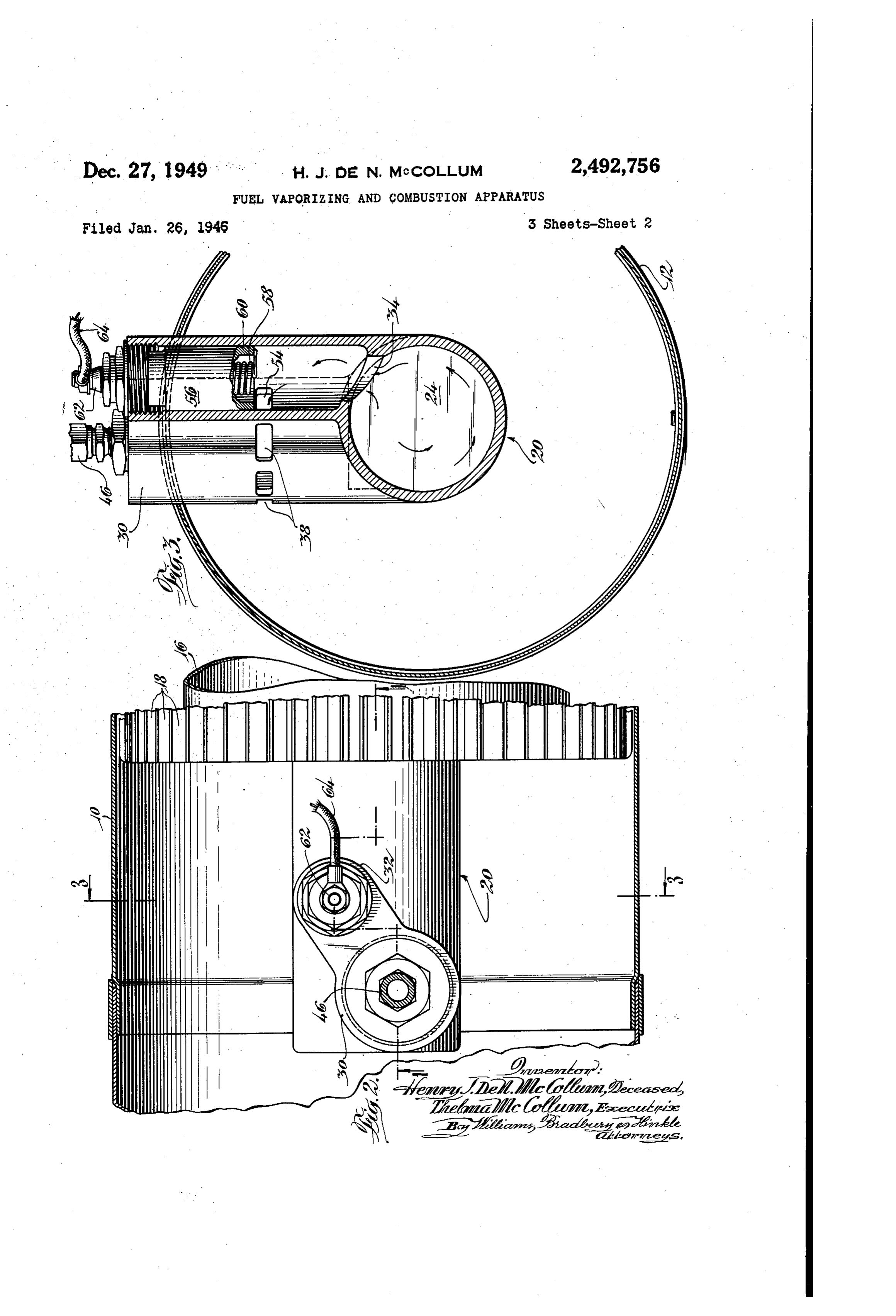
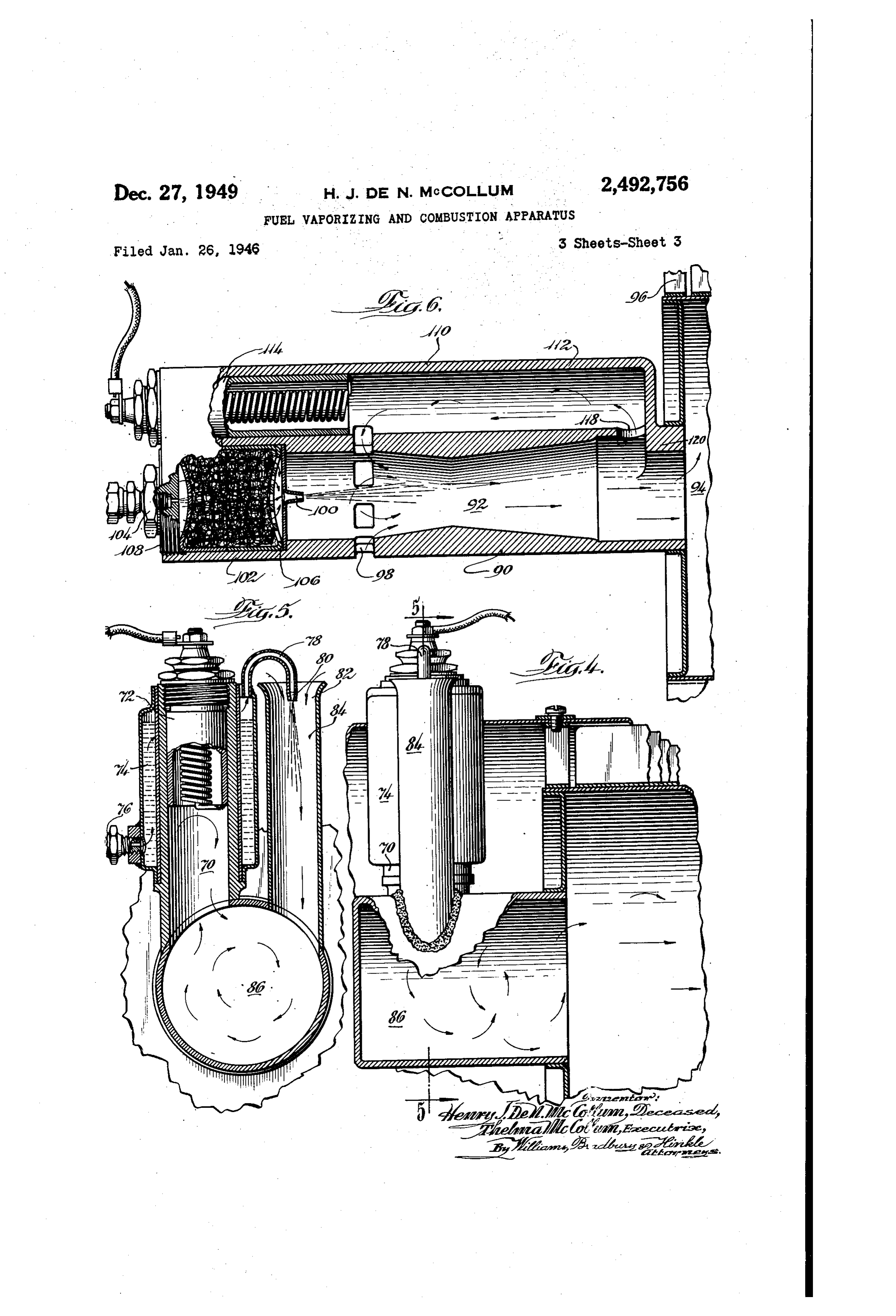
The present invention relates to heating ap as taken in the direction of the arrows along the paratus and, more particularly, to a liquid fuel line 3-3 of Fig. 2;
burner intended for use with automobile and Fig. 4 is a side view of the burner of an alter aircraft type heaters. native form of the present invention with a por As a rule, burners for heaters of the above type 5 tion of the burner broken away to show the in require that some blower means be provided for terior in longitudinal section; forcing air through the combustion side of the Fig. 5 is a transverse sectional view of the heater. In the case of aircraft heaters, rams or burner illustrated in Fig. 4 and may be considered Scoops located exteriorly of the aircraft fre as taken in the direction of the arrows along the quently have been used for this purpose. Al O line 5-5 of Fig. 4; and though burners for more bulky types of heaters Fig. 6 is a longitudinal sectional view of still have frequently dispensed with combustion air another alternative burner embodying the pres blowers and have relied simply upon the rising ent invention, action of the hot products of combustion in a Referring to Figs. 1, 2 and 3, a heater f is stack or chimney to supply the necessary draft, closing as 15 shown comprised of a cylindrical case 2 en a heat exchanger f4. The heat exchanger it will be appreciated that for this simple scheme to work requires either that considerable chimney is8 comprised of a cylindrical shell 6 having fins upon its exterior surface which transfer heat height be provided or that the pressure on the combustion side of the heater be extremely low, from the shell to air flowing through the cylin or Sometimes both. Since the pressure on the 20 drical case, 2, the air passing around the shell heater combustion side cannot be low unless the . 6 and between the fins 8. heat exchange passages be quite open, it is ap At one end, the heater is provided with a burner parent that heaters that do not have forced cir 20 in which hot products of combustion are gep culation on the combustion side must necessarily erated, these products passing into the shell is be heavier and more bulky than heaters which and thence to an exhaust pipe 22 leading away do use Some power consuming combustion air from the space to be heated. circulating means. The burner 20, in which the invention princi One of the objects of the present invention is pally resides, comprises a cylindrical combustion to provide a burner for use in a heater having a chamber 24 which has an opening 26 at One end moderately high pressure on the combustion side 30 connected to the cylindrical shell 6. The op and which dispenses with the requirement of a as posite end of the combustion chamber 24 is closed blower or other power consuming means for cir at 28.
culating the combustion air. The combustion chamber 24 is provided at one An additional object of the present invention is side with a mixture forming chamber 80 which is to provide a burner which creates its own draft 35 its generally cylindrical and which is arranged with regardless of the position in which it operates. axis at right angles with the axis of the com Yet another object of the present invention is bustion chamber 24. The mixing chamber 30 is to provide a novel heater which supplies suf of considerably smaller diameter than the com ficient draft to operate the burner against a con bustion chamber 24 and is offset below the axis siderable combustion side pressure. 40 thereof so that mixture enters the combustion Other objects and advantages will become ap chamber tangentially, thereby producing a swirl parent from the following description of a pre iing motion of the mixture within the combustion ferred embodiment of the invention which is ill chamber. A second tubular extension forming a flash tube 32 is arranged with its axis parallel to lustrated in the accompanying drawings.
In the drawings, in which similar characters of 45 the mixing chamber 30 and connects at one end reference refer to similar parts throughout the chamber with a port 34 in the side of the combustion Several views: 24, but in a position to one side of the Fig. 1 is a longitudinal sectional view of a heater mixing chamber 30, so that swirling action within having a burner embodying the present invention. the combustion chamber produced by the mixing The Section through the burner proper is stag 50 chamber inlet position tends to cause the mixture in the combustion chamber to flow through the gered as indicated by the line - on Fig. 2; -1
Fig. 2 is a side view of the burner illustrated port 34 and into the flash tube 32. The mixing in Fig. 1; chamber 30 is provided internally with a ring 36 Fig. 3 is a transverse sectional view through the which forms a Venturi throat closely adjacent the burner illustrated in Fig.2 and may be considered 65 combustion chamber 2. A row of air inlet open
Page 5
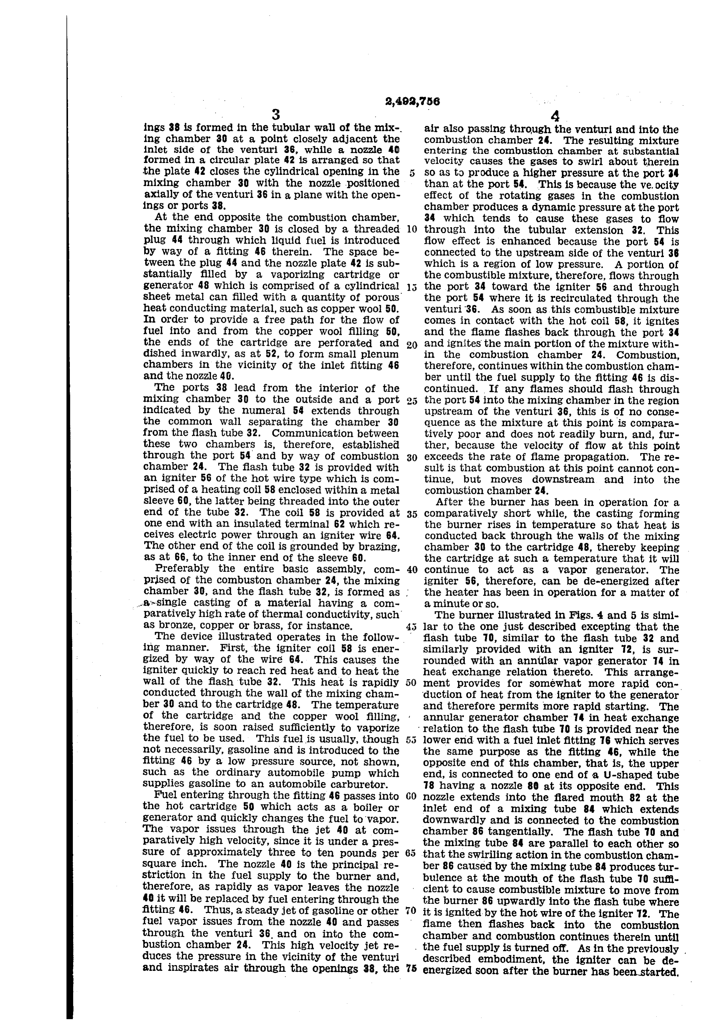
ings 38 is formed in the tubular wall of the mix air also passing through the venturi and into the ing chamber 30 at a point closely adjacent the combustion chamber 24. The resulting mixture inlet side of the venturi 36, while a nozzle 40 entering the combustion chamber at substantial formed in a circular plate 42 is arranged so that velocity causes the gases to Swirl about therein the plate 42 closes the cylindrical opening in the 5 So as to produce a higher pressure at the port 34 mixing chamber 30 with the nozzle positioned than at the port 54. This is because the ve.ocity axially of the venturi 36 in a plane with the open effect of the rotating gases in the combustion ings or ports 38. chamber produces a dynamic pressure at the port At the end opposite the combustion chamber, 34 which tends to cause these gases to flow the mixing chamber 30 is closed by a threaded 10 through into the tubular extension 32. This plug 44 through which liquid fuel is introduced fiow effect is enhanced because the port 54 is by way of a fitting 46 therein. The space be connected to the upstream side of the venturi 36 tween the plug 44 and the nozzle plate 42 is sub which is a region of low pressure. A portion of stantially filled by a vaporizing cartridge or the combustible mixture, therefore, flows through generator 48 which is comprised of a cylindrical the port 34 toward the igniter 56 and through sheet metal can filled with a quantity of porous the port 54 where it is recirculated through the heat conducting material, such as copper wool 50. venturi 36. As soon as this combustible mixture In order to provide a free path for the flow of comes in contact with the hot coil 58, it ignites fuel into and from the copper wool filling 50, and the flame flashes back through the port 34 the ends of the cartridge are perforated and 20 and ignites the main portion of the mixture with dished inwardly, as at 52, to form small plenum in the combustion chamber 24. Combustion, chambers in the vicinity of the inlet fitting 46 therefore, continues within the combustion chann and the nozzle 4G. ber until the fuel supply to the fitting 46 is dis The ports 38 lead from the interior of the continued. If any flames should flash through mixing chamber 30 to the outside and a port 25 the port 54 into the mixing chamber in the region indicated by the numeral 54 extends through upstream of the venturi 36, this is of no conse the common wall separating the chamber 30 quence as the mixture at this point is compara from the flash tube 32. Communication between tively poor and does not readily burn, and, fur these two chambers is, therefore, established ther, because the velocity of flow at this point through the port 54 and by way of combustion 30 exceeds the rate of flame propagation. The re chamber 24. The flash tube 32 is provided with sult is that combustion at this point cannot con an igniter 56 of the hot wire type which is con tinue, but noves downstream and into the prised of a heating coil 58 enclosed within a metal combustion chamber 24.
sleeve 60, the latter being threaded into the outer After the burner has been in Operation for a end of the tube 32. The coil 58 is provided at 35 comparatively short while, the casting forming One end with an insulated terminal 62 which re the burner rises in temperature So that heat is ceives electric power through an igniter wire 64. conducted back through the walls of the mixing The other end of the coil is grounded by brazing, chamber 30 to the cartridge 48, thereby keeping as at 66, to the inner end of the sleeve 60. the cartridge at such a temperature that it will Preferably the entire basic assembly, com 40 continue to act as a vapor generator. The prised of the combuston chamber 24, the mixing igniter 56, therefore, can be de-energized after chamber 30, and the flash tube 32, is formed as the heater has been in operation for a matter of a's single casting of a material having a com a minute or so.
paratively high rate of thermal conductivity, such The burner illustrated in Figs. 4 and 5 is simi as bronze, copper or brass, for instance. lar to the one just described excepting that the The device illustrated operates in the follow fiash tube 70, similar to the flash tube 32 and ing manner. First, the igniter coil 58 is ener similarly provided with an igniter 2, is Sur gized by Way of the wire 64. This causes the rounded with an annular vapor generator 74 in igniter quickly to reach red heat and to heat the heat exchange relation thereto. This arrange Wall of the flash tube 32. This heat is rapidly ment provides for somewhat more rapid con conducted through the wall of the mixing cham duction of heat from the igniter to the generator ber 30 and to the cartridge 48. The temperature and therefore permits more rapid starting. The of the cartridge and the copper wool filling, annular generator chamber 4 in heat exchange therefore, is soon raised sufficiently to vaporize relation to the flash tube T0 is provided near the the fuel to be used. This fuel is usually, though 5 5 lower end with a fuel inlet fitting 76 which serves not necessarily, gasoline and is introduced to the the same purpose as the fitting 46, while the fitting 46 by a low pressure source, not shown, opposite end of this chamber, that is, the upper Such as the ordinary automobile pump which end, is connected to One end of a U-shaped tube Supplies gasoline to an automobile carburetor. 78 having a nozzle 80 at its opposite end. This Fuel entering through the fitting 46 passes into nozzle extends into the flared mouth 82 at the the hot cartridge 50 which acts as a boiler or inlet end of a mixing tube 84 which extends generator and quickly changes the fuel to vapor. downwardly and is connected to the combustion The vapor issues through the jet 40 at com chamber 86 tangentially. The flash tube 70 and paratively high velocity, since it is under a pres the mixing tube 84 are parallel to each other so Sure of approximately three to ten pounds per that the SWiriling action in the combustion cham Square inch. The nozzle 40 is the principal re ber 86 caused by the mixing tube 84 producestur striction in the fuel supply to the burner and, bulence at the mouth of the flash tube 70 Sufi therefore, as rapidly as vapor leaves the nozzle cient to cause combustible mixture to move from 40 it will be replaced by fuel entering through the the burner 86 upwardly into the flash tube where fitting 46. Thus, a steady jet of gasoline or other it is ignited by the hot wire of the igniter T2. The fuel vapor issues from the nozzle 40 and passes flame then flashes back into the combustion through the venturi 36. and on into the com chamber and combustion continues therein until bustion chamber 24. This high velocity jet re , the fuel supply is turned off. As in the previously duces the pressure in the vicinity of the venturi described embodiment, the igniter can be de and inspirates air through the openings 38, the 75 energized soon after the burner has been started.
Page 6
sease
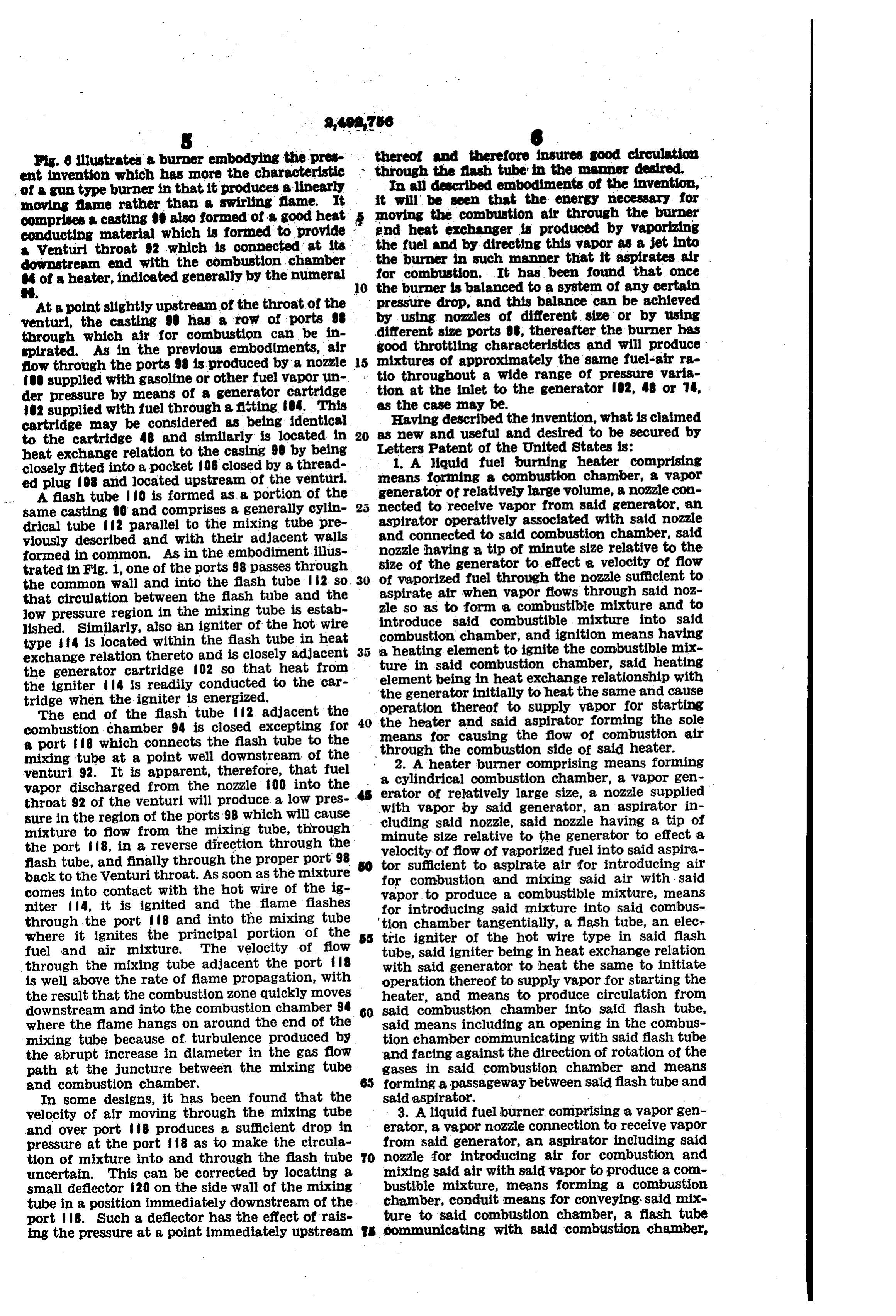
Fig. 6 illustrates a burner embodying the pre thereof and therefore insures good circulation ent invention which has more the characteristic through the flash tube in the manner desired. of a gun type burner in that it produces a linearly In all described embodiments of the invention, moving flame rather than a swirling fame. It it will be seen that the energy necessary for comprises a casting 9D also formed of a good heat moving the combustion air through the burner conducting material which is formed to provide the end heat exchanger is produced by vaporizing adownstream venturi throat 92 which is connected at its the fuel end with the combustion chamber and by directing this vapor as a jet into burner in such manner that it aspirates air 4 of a heater, indicated generally by the numeral for combustion. It has been found that once O. . . . . 0 the burner is balanced to a system of any certain At a point slightly upstream of the throat of the pressure drop, and this balance can be achieved venturi, the casting 90 has a row of ports 9 by using nozzles of different size or by using through which air for combustion can be in different size ports 98, thereafter the burner has spirated. As in the previous embodiments, air good throttling characteristics and will produce flow through the ports 98 is produced by a nozzle 15 mixtures of approximately the same fuel-air ra O supplied with gasoline or other fuel vapor un to throughout a wide range of pressure varia der pressure by means of a generator cartridge tion at the inlet to the generator 02, 48 or 74, O2 supplied with fuel through a fitting 04. This as the casedescribed may be.
cartridge may be considered as being identical as Having the invention, what is claimed new and useful and desired to be secured by to the cartridge 48 and similarly is located in 20 heat exchange relation to the casing 90 by being Letters Patent of the United States is: 1. A liquid fuel burning heater comprising closely fitted into a pocket 106 closed by a thread ed plug 08 and located upstream of the venturi. means forming a combustion chamber, a vapor generator of relatively large volume, a nozzle con
A flash tube O is formed as a portion of the same casting 0 and comprises a generally cylin 5 nected to receive vapor from said generator, an drical tube ff2 parallel to the mixing tube pre aspirator operatively associated with said nozzle viously described and with their adjacent walls and connected to said combustion chamber, said formed in common. As in the embodiment illus nozzle having a tip of minute size relative to the trated in Fig. 1, one of the ports 98 passes through size of the generator to effect a velocity of flow the common wall and into the flash tube 2 so, 30 of vaporized fuel through the nozzle sufficient to that circulation between the flash tube and the aspirate air when vapor flows through said noz low pressure region in the mixing tube is estab zle so as to form a combustible mixture and to lished. Similarly, also an igniter of the hot wire introduce said combustible mixture into said combustion chamber, and ignition means having type f4 is located within the flash tube in heat a heating element to ignite the combustible mix exchange relation thereto and is closely adjacent ture in said combustion chamber, said heating the generator cartridge 02 So that heat from element being in heat exchange relationship with the igniter 4 is readily conducted to the car the generator initially to heat the same and cause tridge when the igniter is energized.
The end of the flash tube 2 adjacent the 40 operation the heater thereof to supply vapor for starting and said aspirator forming the sole combustion chamber 94 is closed excepting for means for causing the flow of combustion air a port 8 which connects the flash tube to the through the combustion side of said heater. mixing tube at a point well downstream of the 2. A heater burner comprising means forming venturi 92. It is apparent, therefore, that fuel a cylindrical combustion chamber, a vapor gen vapor discharged from the nozzle 00 into the erator of relatively large size, a nozzle supplied throat 92 of the venturi will produce. a low pres ..with vapor by said generator, an aspirator in sure in the region of the ports 98 which will cause cluding said nozzle, said nozzle having a tip of mixture to flow from the mixing tube, through minute size relative to the generator to effect a the port 8, in a reverse direction through the velocity of flow of vaporized fuel into said aspira flash tube, and finally through the proper port 98tor sufficient to aspirate air for introducing air back to the Wenturi throat. As soon as the mixturefor combustion and mixing said air with . said comes into contact with the hot wire of the ig vapor to produce a combustible mixture, means niter 4, it is ignited and the flame flashes for introducing said mixture into said combus through the port 8 and into the mixing tube tion chamber tangentially, a flash tube, an elec where it ignites the principal portion of the tric igniter of the hot wire type in said flash fuel and air mixture. The velocity of flow tube, said igniter being in heat exchange relation through the mixing tube adjacent the port f8 with said generator to heat the same to initiate is well above the rate of fame propagation, with operation thereof to supply vapor for starting the the result that the combustion zone quickly moves heater, and means to produce circulation from downstream and into the combustion chamber 94 60 said combustion chamber into said flash tube, where the flame hangs on around the end of the said means including an opening in the combus mixing tube because of turbulence produced by tion chamber communicating with said flash tube the abrupt increase in diameter in the gas flow and facing against the direction of rotation of the path at the juncture between the mixing tube gases in said combustion chamber and means and combustion chamber. forming a passageway between said flash tube and In some designs, it has been found that the said aspirator. A.
velocity of air moving through the mixing tube 3. A liquid-fuel burner comprising a vapor gen and over port 8 produces a sufficient drop in erator, a vapor nozzle connection to receive vapor pressure at the port f8 as to make the circula from said generator, an aspirator including said tion of mixture into and through the flash tube O nozzle for introducing air for combustion and uncertain. This can be corrected by locating a mixing said air with said vapor to produce a com small deflector 20 on the side wall of the mixing bustible mixture, means forming a combustion tube in a position immediately downstream of the chamber, conduit means for conveying said mix port 8. Such a deflector has the effect of rais ture to said combustion chamber, a flash tube ing the pressure at a point immediately upstream S Communicating with said combustion chamber,
Page 7
and an igniter of the hot wire type in said flash to start the heater; said structure being in heat tube, said flash tube including wall structure dis exchange relation with said combustion chamber posed in heat exchange relation with said igniter to maintain the generator heated during Con and generator and said combustion chamber and tinued operation of the heater, means forming an generator. aspirator in said body structure having an out 4. A liquid fuel burner for a heater of the type let communicating with said combustion cham which has high pressure characteristics on the ber, and a nozzle arranged to discharge the vapors combustion side, said burner comprising a con ized fuel generated by said generator axially of bustion chamber, a mixing tube connected to said aspirator for causing the same to aspirate air discharge into said combustion chamber, Said 0 for mixture with the vaporized fuel to form a mixing tube including air inlet openings, a vapor combustible mixture, said body structure includ generator, a nozzle connected to receive vapor ing a tubular portion establishing communica from said generator, said nozzle being aligned to tion between said combustion chamber and igniter project vapor substantially axially of Said mixing for receiving a portion of the combustible mixture tube and past said openings, a flash tube igniter s discharged into said combustion chamber to in associated with said mixing tube including an itiate combustion.
igniter element of the hot wire type, said element 7. In a liquid fuel burning heater having a heat being arranged in heat transfer relationship to exchanger and a burner including means form said generator, means forming a heat conducting ing a combustion chamber for producing hot path from said combustion chamber to said gen 20 products of combustion and for passing said erator, said flash tube having two communicating products of combustion to said heat exchanger, connections to said mixing tube, one of these con said burner comprising a vapor generator, a noz nections being located relative to the mixing tube zle supplied with vapor by Said generator, an downstream of the other, and said hot wire igniter aspirator including said nozzle for introducing element being closely adjacent the farther up- ; air for combustion and mixing said air with said stream of said connections. vapor to produce a combustible mixture, means 5. A liquid fuel burner adapted for use with a for introducing said mixture into said combus heater having high combustion side pressure tion chamber, a flash tube communicating with characteristics comprising means forming a cylin said burner, and an electric igniter of the hot drical combustion chamber closed at one end, a 30 wire type in said flash tube, Said igniter and gen heat exchanger connected to the opposite end of erator being separated by structure including a said combustion chamber, a mixing tube con wall in heat exchange relation with said genera nected tangentially to said combustion chamber, tor and with said combustion chamber. said mixing tube having its opposite end open to the atmosphere, a flash tube arranged parallel 35 THELMA McCOLLUM, to said mixing tube, said flash tube being con Eacecutriac of the Last Will and Testament of nected to said combustion chamber tangentially Henry J. De N. McCollum, Deceased. thereof, an igniter of the hot wire type located REFERENCES CTED in said flash tube, an annular vapor generator surrounding said flash tube and at least a por The following references are of record in the tion of the igniter therein, a liquid fuel connec file of this patent:
tion to said generator at one end, a vapor outlet UNITED STATES PATENTS tube connected to the opposite end of said gen Number Name Date erator, said outlet tube having its opposite end formed to provide a nozzle, and said tube being 45 1,381,273 Blanchard --------- June 14, 1921 bent to locate said nozzle adjacent the inlet end 1,656,486 Huntington et al. ---- Jan. 17, 1928 of said mixing tube so that said nozzle is adapted 1,670,819 Morris et al. -------- May 22, 1928 to direct a jet of vapor into said mixing tube. 1,777,732 Pearson ------------ Oct. 7, 1930 6. A liquid fuel burning heater comprising 1839,512 Waterman ---------- Jan. 5, 1932
means forming a combustion chamber, a genera 50 2,110,222 Curioni ------------- Mar. 9, 1937 tor for vaporizing liquid fuel, an igniter of the Hammers et al. ------ Mar. 8, 1938 hot wire, type, body structure for housing said 2,117,108 Spencer ------------ May 10, 1938 igniter and generator spaced from said combus 2,229,717 Brace et al. --------- Jan. 28, 1941 tion chamber and including a wall separating said 2,286,854 Holthouse ---------- June 16, 1942 igniter and generator and adapted to be initially 55 2,395,418 McCollum ---------- Feb. 26, 1946 heated by said igniter for heating said generator 2,455,207 Willians ----------- Nov. 30, 1948
Provenance
- Collection
- Cited prior art
- Original PDF
- patentimages.storage.googleapis.com →
- Filed
- 1946-01-26
- Pages
- 7
- Method
- pdftotext (the PDF's own text layer) + pdftoppm 300dpi page scans
- Source
- Google Patents bibliographic record
- Granted
- 1949-12-27
- Inventors
- Mccollum Thelma; Stewart Warner Corp
- Transcribed from
- patentimages.storage.googleapis.com →