patent · US3134423
Ignition arrangement for pot-type liquid fuel burner
26 May 1964
Page 1
Drawing sheet — no readable text.
Page 2
United States Patent Office 3,134,423 Patiented May 26, 1964
ent purposes, will be assumed to be in a clockwise direc 3,34,423 tion as viewed looking down upon the pot interior and
GNETSBN ARRANGE/ENT FOR P3OT-TYPE as indicated by the directional arrows (FIGURE 2). ; UED FJEL SBURNER The basic ignition arrangement includes: an ignition Hersert G. Saifi, lyioline, i., assignor to American Air 5 chamber 24 secured to the exterior of the casing circum Filter
Feayyare
Company, i.e., Soisie, Ky., a corporation of ferential wall A4; a fiane passage 26 extending from the Filed July 5, 96, Ser. No. 21943. ignition chamber through the annular space 18 to the 7 Caias. (C. 58-9) pot interior; an air supply tube 28 connecting the interior of the ignition chamber with the annular space so that
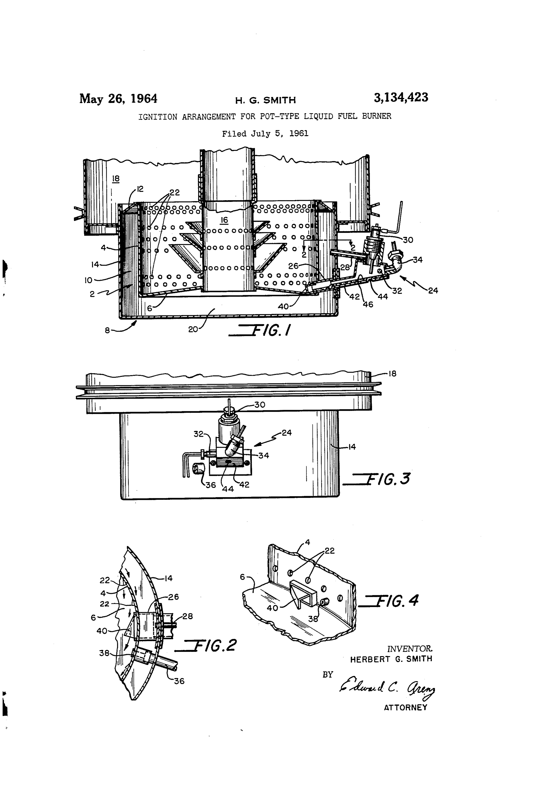
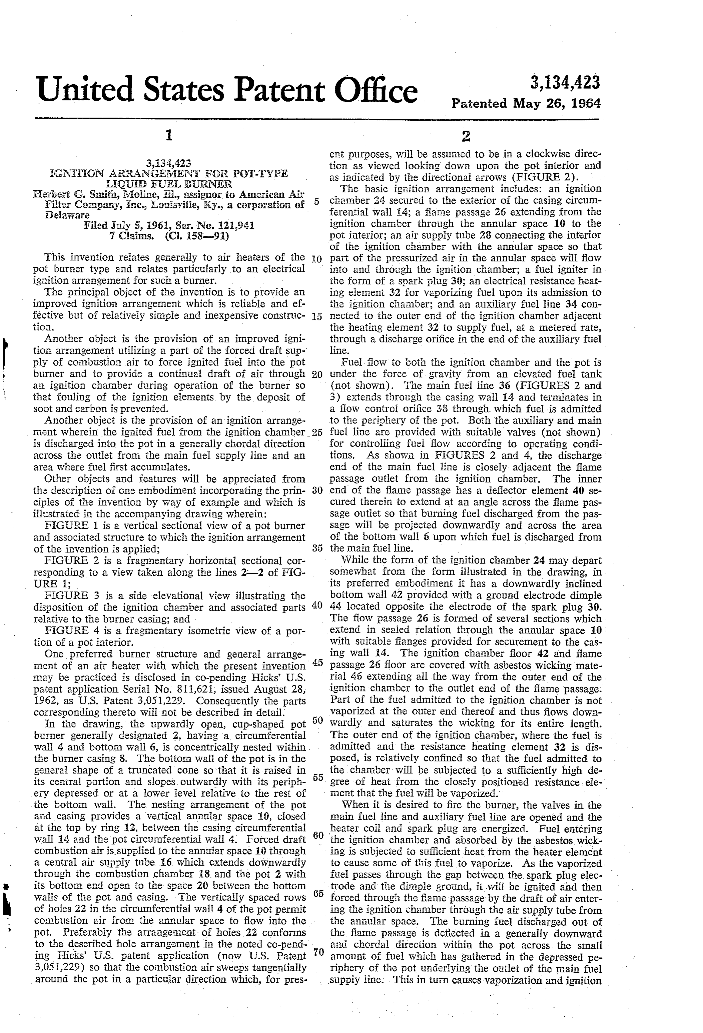
This invention relates generally to air heaters of the O part of the pressurized air in the annular space will flow pot burner type and relates particularly to an electrical into and through the ignition chamber; a fuel igniter in ignition arrangement for such a burner. the form of a spark plug 30; an electrical resistance heat The principal object of the invention is to provide an ing element 32 for vaporizing fuel upon its admission to improved ignition arrangement which is reliable and ef the ignition channber; and an auxiliary fuel line 34 con fective but of relatively simple and inexpensive construc 5 nected to the outer end of the ignition chamber adjacent tion. the heating element 32 to Supply fuel, at a metered rate, Another object is the provision of an improved igni through a discharge orifice in the end of the auxiliary fuel tion arrangement utilizing a part of the forced draft sup line.
ply of combustion air to force ignited fuel into the pot fuel flow to both the ignition chamber and the pot is burner and to provide a continual draft of air through 20 under the force of gravity from an elevated fuel tank an ignition chanber during operation of the burner so (not shown). The main fuel line 36 (FIGURES 2 and that fouling of the ignition elements by the deposit of 3) extends through the casing wall 14 and terminates in soot and carbon is prevented. a flow control orifice 38 through which fuel is admitted Another object is the provision of an ignition arrange to the periphery of the pot. Both the auxiliary and main ment wherein the ignited fuel from the ignition chamber 25 fuel line are provided with suitable valves (not shown) is discharged into the pot in a generally chordal direction for controlling fuel flow according to operating condi across the outlet from the main fuel supply line and an tions. As shown in FIG URES 2 and 4, the discharge area where fuel first accumulates. end of the main fuel line is closely adjacent the flame Other objects and features will be appreciated from paSSage outlet from the ignition chamber. The inner the description of one embodiment incorporating the prin 30 end of the flame passage has a deflector element 40 se ciples of the invention by way of example and which is cured therein to extend at an angle across the flame pas illustrated in the accompanying drawing wherein: Sage outlet So that burning fuel discharged from the pas FIGURE 1 is a vertical sectional view of a pot burner Sage will be projected downwardly and across the area and associated structure to which the ignition arrangement of the botton wall 6 upon which fuel is discharged from of the invention is applied; 35 the main fuel line.
FIGURE 2 is a fragmentary horizontal sectional cor While the form of the ignition chamber 24 may depart responding to a view taken along the lines 2-2 of FIG Somewhat from the form illustrated in the drawing, in URE 1; its preferred embodiment it has a downwardly inclined FIGURE 3 is a side elevational view illustrating the botton wall 42 provided with a ground electrode dimple disposition of the ignition chamber and associated parts 40 44 located opposite the electrode of the spark plug 30. relative to the burner casing; and The flow passage 26 is formed of several sections which FIGURE 4 is a fragmentary isometric view of a por extend in Sealed relation through the annular space 10, tion of a pot interior. With Suitable flanges provided for securement to the cas One preferred burner structure and general arrange ing Wall 4. The ignition chamber floor 42 and fiane ment of an air heater with which the present invention 45 passage 26 floor are covered with asbestos wicking mate may be practiced is disclosed in co-pending Hicks’ U.S. rial 45 extending all the way from the outer end of the patent application Serial No. 811,621, issued August 28, ignition chamber to the outlet end of the flame passage. 1962, as U.S. Patent 3,051,229. Consequently the parts Part of the fuel admitted to the ignition chamber is not corresponding thereto will not be described in detail. vaporized at the outer end thereof and thus fows down In the drawing, the upwardly open, cup-shaped pot 50 Wardly and Saturates the wicking for its entire length. burner generally designated 2, having a circumferential The outer end of the ignition chamber, where the fuel is Wall 4 and botton wall 6, is concentrically nested within admitted and the resistance heating element 32 is dis the burner casing 8. The bottom wall of the pot is in the posed, is relatively confined so that the fuel admitted to general shape of a truncated cone so that it is raised in the chamber will be subjected to a sufficiently high de its central portion and slopes outwardly with its periph 55 gree of heat from the closely positioned resistance, ele ely depressed or at a lower level relative to the rest of ment that the fuel will be vaporized. the botton waii. The nesting arrangement of the pot When it is desired to fire the burner, the valves in the and casing provides a vertical annular space E0, closed main fuel line and auxiliary fuel line are opened and the at the top by ring 12, between the casing circumferential heater coil and Spark plug are energized. Fuel entering wall 14 and the pot circumferential wall 4. Forced draft the ignition chamber and absorbed by the asbestos wick combustion air is supplied to the annular space 18 through ing is subjected to sufficient heat from the heater element a central air supply tube 6 which extends downwardly to cause Some of this fuel to vaporize. As the vaporized. through the combustion chamber 18 and the pot 2 with fuel passes through the gap between the spark plug elec its bottom end open to the space 20 between the bottom 65 trode, and the diaple ground, it will be ignited and then walls of the pot and casing. The vertically spaced rows forced through the flame passage by the draft of air enter of holes 22 in the circumferential wall 4 of the pot permit ing the ignition chamber through the air supply tube from - combustion air from the annular space to flow into the the annular space. The burning fuel discharged out of pot. Preferabiy the arrangement of holes 22 confortins the flame passage is defected in a generally downward to the described hole arrangement in the noted co-pend O and chordal direction within the pot across the small ing Hicks’ U.S. patent application (now U.S. Patent amount of fuel which has gathered in the depressed pe 3,051,229) So that the combustion air sweeps tangentially riphery of the pot underlying the outlet of the main fuel around the pot in a particular direction which, for pres Supply line. This in turn causes vaporization and ignition
Page 3
of this fuel in the pot. Since combustion in the pot, once the circumferential wails of said pot and said casing, said established, is self-sustaining so long as additional fuel is circumferential waii of said pot having aperture means supplied, the supply of fuel to the ignition chamber, and for admitting air from said annular space into said pot; energization of the heating element and igniting element, means for supplying said annular space with a part of may then be terminated. However, the flow of air through said forced draft combustion air; main fuel supply means the ignition chamber will continue while the draft of con having an outlet opening above a first peripheral loca bustion air continues. This airflow prevents fouling of tion on said botton wall of said burner pot for admit elements in the ignition chamber by combustion impuri ting fuel to said location; an ignition chamber on the . . . ties generated in the pot. exterior of said casing; means for supplying fuel to said It will be appreciated that the forced draft supply of 10 ignition chamber; means for igniting said fuel Supplied air to the ignition chamber permits vaporization and igni to said ignition chamber; an air supply tube connecting . tion to take place readily within the chamber even though said annular space to said ignition chamber; a flame pas the chamber is rather small. The pressurized ignition sage connecting said ignition chamber to said burner pot chamber also permits the use of a cross sectionally small interior to admit said ignited fuel to said burner pot along flame passage which minimizes the obstruction in the an 15 side said first peripheral location; and deflection, means nular space 10. The provision of the wicking material at the inner end of said fame passage shaped to deflect along the entire length of the fame passage insures a said ignited fuel in a single chordal direction relative to Supply of fuel available for vaporization and ignition for the curve of said pot across said first peripheral location. the entire length of the fame passage which in turn as 4. The air heater specified in claim 3 wherein: said sures retention of a fire in the flame passage and the 20. apertures in the circumferential waii of the burner pot continued propagation of the fame to the pot during the are canted to admit air in a swirling motion into said ignition operation. This is particularly advantageous un pot; and said deflection means directs said ignited fuel der cold start conditions with relatively low temperatures in the saile direction. . . . . . - when a flame passing through the flame passage might - 5. The combination of a liquid fuel burner of the cir otherwise be snuffed out. -- - 25 cular pot type and an ignition arrangement therefor com The invention claimed is: prising: a truncated cone-shaped floor for said pot pro 1. In an air heater of the type having a circular burner. viding a depressed periphery; pot fuel supply means hav pot to which a forced draft of combustion air is supplied: ing an outlet opening above a first location of said de a pot-floor having a depressed portion at its periphery; pressed periphery for supplying fuel to said location; a main fuel line means having an outlet opening above a 30 pot-shaped casing in which said pot is nested to form an first peripheral location of said depressed portion for ad annular space between the circumferential wall thereof; mitting fuel by gravity flow to said location; a fuel igni means to supply said annular space with a forced draft tion chamber beside said burner pot; auxiliary fuel line of air; an ignition chamber mounted on the exterior of means for admitting fuel to said chamber; fuel ignition said casing, said chamber having a bottom wall sloping means in said chamber; ignition chamber air supply downwardly toward said pot; an air supply tube connect means for admitting a portion of said forced draft com ing said annular space with said ignition chamber; a flame bustion air thereto; and an ignition chamber discharge passage connecting said ignition chamber with said pot passage extending to said pot interior with an outlet along interior, said flame passage outlet being alongside the side said first peripheral location, said outlet having de outlet of said fuel supply means to said pot and closely flector means projecting generally chordally relative to adjacent said floor; means for supplying fuel to the outer - the curve of said pot and shaped to deflect burning fuelin end of Said ignition chamber; means for igniting said fuel ation.
single chordal direction across said first- peripheral loca in said ignition chamber; and deflection means at the . . . . . .. outlet end of said flame passage shaped to direct fire exit 2. In a liquid fuel burner of the type having a circular sing therefrom downwardly, and in a single chordal di burner pot nested within a casing to form an annular rection relative to the curve of said pot, across the por space between the circumferential walls thereof and to tion of said depressed periphery to which fuel is dis - which space air for combustion is forced: means forming. charged from said pot fuel supply means. . . . . - a depressed area in the bottom wall of said burner pot c.6. The combination specified in claim 5 wherein: said adjacent the periphery thereof; a main fuel line having ignition chamber has a progressively smaller interior cross an outlet opening above a first peripheral location of said 50 section toward said outer end; heater means is provided. depressed area for supplying fuel to said location; a fuel. closely adjacent said outer end to vaporize fuel admitted ignition chamber on the side of said casing; an auxiliary thereto; and said ignition means is a spark gap type igniter fuel line for supplying fuel to said ignition chamber; between said heater and said flame passage. . means for igniting said fuel supplied to said ignition cham 55 7. The combination specified in claim 6 including: ber; means connecting said annular space with said igni wicking material substantially covering the bottom wall of tion chamber to create a draft of air therethrough; a flame: said ignition chamber and the length of said flame passage. : passage connecting. said ignition chamber with said-pot .
interior, the outlet of said flame passage being alongside. References Cited in the file of this patent said first peripheral location; and deflection means at the 60 UNITED STATES PATENTS inner end of said frame passage shaped to deflect the ignited fuel exiting from said fiane passage in a single 1,408,277 - Ensign ----------------
chordal direction relative to the curve of said pot across 1,427,059 Bridgford et al. - Aug. 22, 1922 said first peripheral location. 2,388,907. De Lancey.-------- -- Nov. 13, 1945. 3. In an air heater of the type having a burner pot to 65. 2,659,428 - Judson --------------Nov. 17, 1953. which a forced draft of combustion air is. Supplied: a 2,729,282. Lennox. ------- 1956: burner casing; a circular burner pot, having a truncated . 2,966,943. Breese -----. 1961 cone-shaped bottom wall and a circumferential wall, 2,983,313 s, 1961. nested in said casing to form an annular space between.
Provenance
- Collection
- Cited prior art
- Original PDF
- patentimages.storage.googleapis.com →
- Filed
- 1961-07-05
- Pages
- 3
- Method
- pdftotext (the PDF's own text layer) + pdftoppm 300dpi page scans
- Source
- Google Patents bibliographic record
- Granted
- 1964-05-26
- Inventors
- Herbert G Smith; American Air Filter Co Inc
- Transcribed from
- patentimages.storage.googleapis.com →