patent · US2048321
Fuel burning apparatus
21 July 1936
Page 1
Drawing sheet — no readable text.
Page 2
Drawing sheet — no readable text.
Page 3
Paterated July 2, 1936 248,321
UNITED STATES PATENT OFFICE
FUEL BURNING APPARATUS
Eben H. Carruthers and Dana B. Green, thaca, N. Y.
Application June 8, 1933, Seria No. 674,804
This invention pertains to the art of combus A preheated supply of supplementary air may be fed upwardly around the hood perimeter and tion controls, and more particularly relates to an into improved burner hood capable of handling gase the respective outermost conduit ends. The ous fuels or the like combustibles, and further re vacuum influence created along the contracted lates to associated appurtenances adapted to nozzle zone of each such oil-gas jet is utilized to thoroughly atomize and efficiently burn the suck supplementary air radially inward and heavier grades of liquid fuel in either small or lengthwise of the several upwardly sloping con duits toward the raised apex of our hood. Cer large sized units for use in new or existing house tain hold heaters, boilers or the like furnace devices. localized hood regions including the burn 0. In the present system, such atomized liquid er center are thereby fed by an independently 0. fuel is preferably burned in a stepwise or multi conveyed air stream rather than being obliged to indiscriminately pick up the required air quota,
Zone manner, being initially mixed with a rea, from the surrounding atmosphere. stricted, minor body of primary air that in itself is insufficient to support complete combustion but Such final crossfeeding of air into the burner 5 5 adequate to vaporize all such fuel into a preheat flame serves to thoroughly mix the constituents ed oil-gas state or the like combustible. Our and to automatically fix in a fairly definite and burner may be provided with a horizontally dis maintained proportion, the ratio of oil-gas to the air needed to complete its combustion, particul posed hood preferably having a cross-sectionally larly so as applied to burners of relatively large crowned shape that is radially slitted or otherwise capacity. The issuing fuel may thereby be 20 20 given a plurality of similar jet apertures there through, and which jet slits are placed in a cross the minimum quotathe burned throughout
length of our jet slits with air consistent with perfect wise relation to a centralized upturned atomiz combustion; the resulting high ing nozzle. This nozzle is preferably encased in promotes efficiency and tendsflame temperature to eliminate the 25 venturi fashion within the contracted end of a flared tubular housing and the enlarged up formation of flue Soot.
In order to attain a steady and noiseless initial turned end of which housing is bridged by the combustion of liquid fuel in the atomizing noz aforesaid hood member. The partially burned zle region, inert or the like spent flue gases, may oil-gas while flowing upwardly through said hous be continuously introduced in the vicinity of the 30 ing, is allowed to expand laterally for distribu injected fuel spray to bring about a more gradual 30 tion through the various jet apertures, whereupon
Said oil-gas or combustible is additionally mixed or retarded rate of combustion on part of the primary air mixture that shall be free from with a major portion of supplementary air that completes combustion of Such oil-gas immedi flutter. .
The object of our invention is to devise an in 35 ately upon its being ejected from the respective hood sits. proved burner of the character indicated and to For present purposes, the well known jet suc construct the necessary instrumentalities with which to carry out the cited underlying princi tion principle is applied in an improved manner to produce a novel result in flame distribution ples of operation including a tubular shell within over the whole of the upturned or upper hood whose confines the combustion chamber is neatly 40 40 surface. The Supplementary air quota required encased in unitary fashion, all of which features to complete combustion of the oil-gas is prefer willAsbea hereinafter more explicitly set forth. primary purpose, it is emphasized that ably fed radially inward from the hood perimeter each crossfeedhood channel is herein so arranged toward its embraced center region in order to ef fect a well distributed, short flame formation. that a supply of fresh air when introduced into 45 45 To this end, our crowned hood surface may be the outer channel end, may be conveyed inwardly charinelled with one or more crossfeed conduits along said channel toward the medial region of our burner hood and which air is kept segregated that are respectively interposed between certainfor delivery in its initial state of purity to one or of Our jet slits; the bottom confines of each such more jet apertures without flow interference or 50 channel is preferably kept depressed or sunken pollution by spent products of combustion that 50 with respect to the aforesaid hood surface in an may simultaneously issue from other contiguous upwardly inclined relation to the contiguous jet jets, until all of such conveyed fresh air has been discharge edges that lie to each channel side, so sucked into and mixed with the combustible that as to bring the delivery of said conduit into the is being ejected through the respective jet aper intended cooperative feed relationship with the tures served by said channel. By the use of a 55 55 elected oil-gas.
Page 4
plurality of radial slits or equivalent rows of jet minates in a spray nozzle 24, said nozzle being apertures when fed by, such crossfeed conduit upturned in axial alignment with the flared hous means, we are enabled to efficiently distribute a ing and its Wenturi port 6.
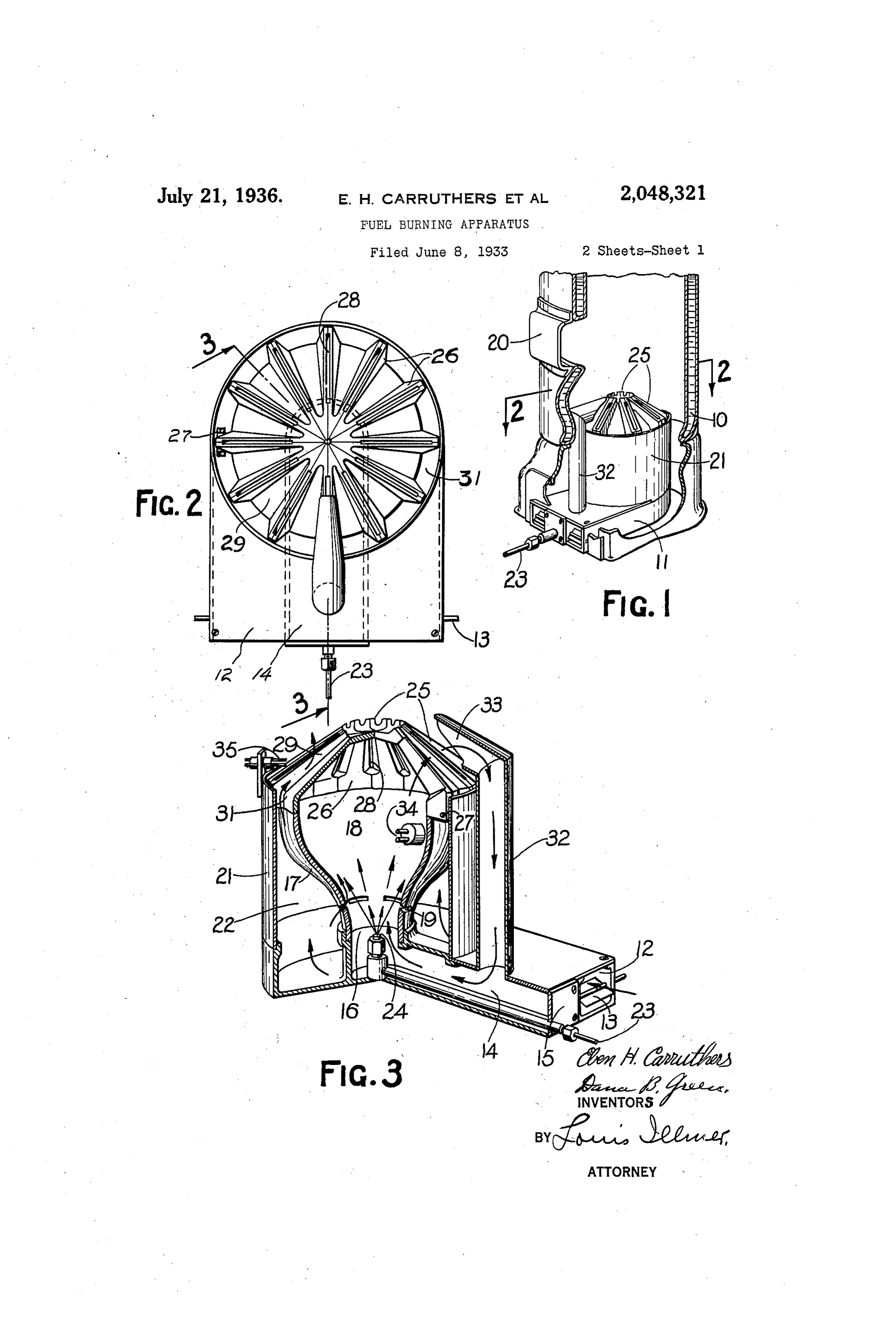
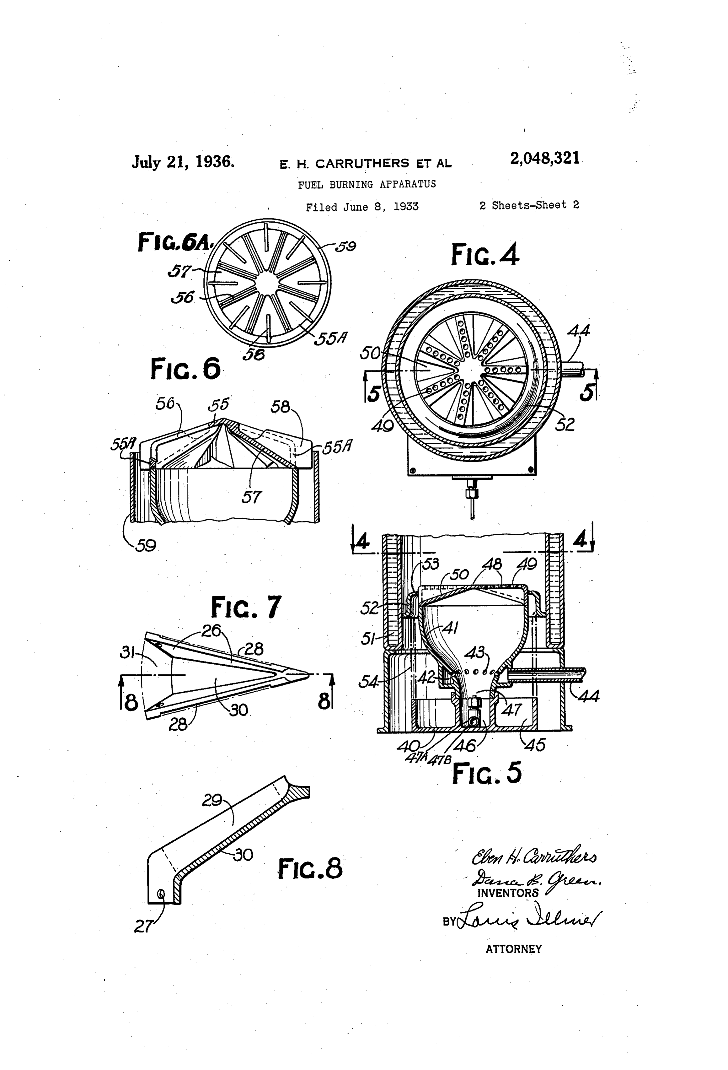
flame over a hood surface of wide extent and still Such centralized nozzle is preferably served by maintain a virtually identical mixture proportion a controllable fuel pump (not shown) of any suit- 5 between the ejected gaseous combustible and itsable motor driven type adapted to thoroughly proper quota of air along the entire length of the atomize liquid fuel and thereby project a spray respective slits or jet rows and which mixture upwardly from the Venturi port in the diverging can be made to burn with substantially the same manner indicated in Fig. 3. This spray is in 10 relative short blue flame characteristic in both tended to be sufficiently powerful to give the re O the inner and outer surface regions of our hood. quired impetus to the Surrounding gaseous me Reference is had to the accompanying two dium so as to create a slight pressure head in the sheets of drawings which are illustrative of sev uppermost Or hood region of the combustion eral alternative embodiments of our invention, chamber 8; also to suck the desired amount of 5 and in which drawings: primary air into said combustion chamber out of 15 Fig. 1 is an upright perspective view of a con the air passage 22 through the inspirator port ventional household boiler or the like furnace as 9, the latter being placed under the influence, sembly of which its jacket is partially broken of the slight vacuum that is created by the ejected away to show our oil burner equipment installed fuel oil in the lowermost nozzle region of our 20 therein. combustion chamber. Said inspirator port is 20 Fig. 2 represents a top view of our preferred definitely sized to restrict the resulting air flow style of burner devices as seen from line 2-2 of within limits that will merely promote incomplete : Fig. 1 but as removed from the boiler jacket, while combustion of the sprayed fuel and thereby form Fig. 3 depicts an elevational cross-section taken an unsatisfied oil-gas mixture needing an addi 25. along the offset line 3-3 of Fig. 2 to schemati tional air quota to complete its combustion. The 25, cally illustrate certain interior details of our air content that is allowed to initially mix with burner structure, the atomized fuel, may be reduced by raising and Fig. 4 shows a top view of a modified burner thereby placing the inspirator port 9 in a more hood assembly and Fig. 5 is a transverse section femote position with respect to the intensified 30 thereof along line 5-5 of Fig. 4, while Fig. 6 Suction zone of the nozzle 24. 30 fragmentally reveals still another style of hood Our apertured burner wall or hood shaped of which Fig. 6A illustrates a top view. crown piece 25 is transversely superimposed to Fig. 7 details a plan or top view of one of Our span the flared end of the upstanding housing 7, hood sectors utilized in Fig. 3, and Fig. 8 is a and may be given a cross-sectionally blunt cOne 35 cross-section thereof as taken along line 8-8.
shape or equivalent profile of which the apex is 35
Referring first to Figs. 1 to 3, ?o denotes a water preferably kept elevated in relation to the hood jacket of an upright boiler or the like heating perimeter. Such crowned burner wall may either furnace adapted to have our fuel burner system be cast Solid or built up. from a plurality of sepa-. installed therein. Said burner may comprise a rable and independently expansible hood sectors 40 box shaped, compartmental base casting that Such as 26 of which the respective mated radial 40 is shown provided with a U-shaped, Supplemen faces are assembled to constitute a circular for- : tary air duct enclosure 2. In its yoke end re nation of the kind shown in Fig. 2. ". gion, the top wall of this duct is kept open as These various hood components may be bolted cross-sectionally detailed in Fig. 3 while the re together as at 27 into a unitary assembly having 5 spective perimetrically complete leg end walls of a relatively small imperforate central region from 45 this duct may be extended forwardly through the which the several sector sidefaces radiate. As ash pit door of a boiler as indicated. Interposed detailed in Fig. 7, it is preferred to laterally inset between such duct legs, is a nozzle duct 4 of the medial region of each such sector sideface which the forward end may be sealed by an aper relative to the respective terminal regions thereof 50 tured cover plate 5 while the rearmost duct end so as to provide for a narrow burner slit 28 or the discharges upwardly through a contracted neck equivalent jet aperture between each consecu or Venturi port 6 as shown, it being the intent tive pair of assembled hood sectors. - to so encase said nozzle duct 4 that it shall be kept separated and reasonably airtight with re As disclosed in Figs. 7 and 8, the cross-sectional 55 spect to the adjacent base duct profile of each hood sector is purposely given a 2. Either or troughlike shape to form an upwardly sloping 55 both of said ducts may be equipped with adjust crossfeed channel or conduit 29 as interposed able throttle means such as 3 serving to regulatebetween adjacent burner slits and of which chan-, the flow therethrough.
Resting concentrically about said circular port isnel,kept 60 6, is the contracted end of a flared tubular hous the bottommost confines or wall element 30.
vertically depressed in an inclined co operative feed relationship with respect to the 60 ing 7 serving to form a primary combustion . topmost discharge edges of such adjacent slits. chamber 8 therein. This upright housing may It is preferred to make the upward inclination of be cast of iron and have the upturned mouth. the Wall 30 steeper than the corresponding slope region thereof disposed radially outward with given to the contiguous discharge edges in Order 65 respect to the port 6. Intermediate the housing to afford a gradually rising air flow toward the 65 ends, one or more slots or the like admission feed hood apex that shall uniformly feed the asso ports such as 9 may be formed through the ciated hood slits throughout the length thereof. flared housing wall. It will be obvious that such built-up hood sectors The housing may be circumscribed by the may also be given a flat top formation in the 70 cylindrical shell 2 of which the lowermost end manner of the Fig. 5 disclosure. may be carried upon the top of the base casting At the perimetric region of our hood, the en . is shell encloses an annular air passage larged intake end of the respective crossfeed con way 22 that freely communicates with the duct duits may be directed downwardly around the 2. Entered through the cover plate 5 is an oil flared housing as in Fig. 3 and placed in direct 75 supply line 23 that extends into the duct and ter communication with the annular passageway 22 75.
Page 5
through the air feed ports such as 3 f. When to suck all of the supplementary air radially resorting to an integral burner hood, the up inward and risingly along its upwardly inclined turned surface thereof would likewise be formed sector or bottom plate 30 of the crossfeed con with a series of radially disposed jet apertures duit 29 in a proportionate relation to the oil that similarly have a crossfeed channel 29 inter gas flow. The cited jet suction action imparts pOSed and sunk between the respective consecul mobility to the supplementary air being con tive jet apertures. The hood perimeter is shown veyed along such a channel and ultimately draws centered within the shell 2. Said air laterally over the channel sides. Such As a further structural refinement, we may Sucked air becomes thoroughly intermingled 0 resort to the downcomer pipe 32 whose bottom with the partially burned oil-gas that issues from
the respective hood jets and completes flange may be demountably upheld by the top bustion thereof in a predetermined mixture ratio the com plate of the base casting , said plate being ap ertured to allow said pipe to unobstructedly de requiring the minimum of surplus air or air liver into the encased nozzle duct 14. As shown quota. The major portion of the burner flame 5 in Fig. 3, the uppermost pipe end may be pro lying contiguous to the hood perimeter will be
vided with a mouth piece 33 that spacedly over freely fed with supplementary. air, whereas the hangs certain, of the hood slits and whose intake center hood region draws a relatively . lesser area is suitably proportioned to admit the de amount of such air over a longer feed distance; sired quantity of spent combustion products. it is the intent to so shape and proportion each 20 The mode of operation of the described appur sloping crossfeed conduit that a substantially 20 tenances may be traced as follows: It may here uniform flame characteristic will be attained be pointed out that when applied to furnace pur along the whole length of the various slit jets. poses, our burner is preferably actuated intermit As a result, we are enabled to build our updraft tently, that is to say the burner flame is either burner in sizes possessing a relatively large heat kept full on or shut down completely to suit ing capacity and still utilize substantially all of the crowned space lying within the perimetric 'prevailing heating needs. To this end, the mid confines region of our housing wall may have a primary of our hood as served. electric igniter 34 or equivalent pilot flame in As regards the function of the downcomer 32, serted therethrough to light the atomized fuel oil the overhanging mouth thereof serves to by 30 30 from the instant that the nozzle 24 starts to spray. pass spent flue gases from above the burner for delivery through the nozzle duct 3, whence it is
The associated control equipmerit may be of the conveyed conventional kind (not shown) serving to auto A relatively into the primary combustion chamber. matically stop the fuel pump delivery in the event Small proportion of such diluent or that the sprayed fuel should fail to ignite prompt inert products of combustion, tends to deaden the 35 35 ly or when the boiler pressure rises abnormally. intensity and effectively retard the initial rate of Suitable thermostatic means may also be en combustion on part of the finely atomized fuel oil and thereby eliminate hissing or the like noisy ployed to command the motor driven fuel pump flame disturbances that are frequently encoun and thereby render the installation self regulat ing; on the other hand, the nozzle delivery may tered in fuel oil burners of larger capacity. 40 in certain instances, be manually varied to suit Referring now to the modified burner structure 40 disclosed 'certain special requirements. As a further safe base casting in Figs. 4 and 5, this may comprise a guard against failure to light the sprayed fuel in Fig. 3 except 40 essentially similar to that used mixture, we additionally provide for a secondary for the downcomer pipe 32. igniter 35 or equivalent pilot flame supported by Mounted upon said base is a flared chamber the shell 2 as disposed exteriorly of the primary. housing 4 of which the contracted Venturi tube region is embraced by an annular header passage combustion chamber 8 in a contiguous relation to - 42 one of the several hood slits (see Fig. 3). having one or more radially disposed feed ports Assuming fuel oil to be supplied under pres 43. Said header is here independently Supplied sure into the line 23 and that this is initially with spent products of combustion or the like sprayed through the nozzle 24, the effect will be inert flue gases through the intake pipe 44 from to create a partial vacuum in the vicinity of the anyThesource.
base casting 40 may likewise be equipt with
Venturi tube 6. The open ended base duct 2 takes in atmospheric air of which a limited por an air duct 45 and a nozzle duct 46. The atomizer tion is passed through the admission feed port region 47 nozzle is again disposed at the converging 5 flared combustion chamber and 5 9 and into the combustion chamber 8. As soon directed totheof as a burnable mixture is formed therein, the ig toward the hood as shown. discharge unobstructedly upwardly
Said nozzle is dis niter 34 lights this mixture to initiate incomplete combustion on part of the entered charge; the tinguished in type over the previously described nozzle 24 in that the air required for primary 60 spreading hot burned products then rise up fuel combustion may here be injected through 60 wardly and are distributed through the burner slits 28, whereupon the combustion of the ejected said atomizer nozzle 4, in which event the air oil-gas is completed exteriorly of the primary and liquid fuel supplies may be separately con chamber 8. The supplementary air lying within ducted thereto by the use of concentrically dis the passageway 22 will thereupon become pre posed feed pipes respectively designated 47A and heated by contact with the relatively hot hous 47B and which are similar to those that have ing wall T and which air rises vertically through been more fully illustrated in Fig. 3. Such prac the various perimetric hood ports 3 that respec tice in turn, eliminates the need for any admis tively lead into the enlarged ends of the sector sion air feed ports in association with the flared crossfeed conduits 29. The intended flow path that the 4contracted housing of Fig. 5. It will also be observed of the different fluid bodies may be traced by the tion chamber snuglyend of the flared combus surrounds the divergent arrows of Fig. 3. spray formation and places the ports 43 within As will be understood, the partially burned oil sucking influence of the nozzle Zone. In addition, gas when ejected through the various radial hood the chamber flare allows the flow of incomplete slits, creates a slight vacuum along each of the products of combustion to gradually spread out 75 75 slit discharge edges, which in turn is utilized
Page 6
wardly and thereby insure a substantially uni resorted to, all without departing from the spirit form distribution through all of the hood jets. and scope of our invention heretofore described In this alternative structure, the upturned and more explicitly pointed out in the appended top face of the one piece hood wall 48 is shown claims.
as flat and provided with a series of radially dis We claim: 5 posed jet apertures 49 which may here be carried 1. In a burner of the multizone type, the con diametrically across the hood center. Between bination of a tubular combustion chamber of each such group of aligned jets, our hood wallis which one end region is contracted to constitute again channeled and shaped to provide for a
O relatively depressed and upwardly inclined bot Venturi tube means, a hood disposed to bridge tom wall element 50. In lieu of a cylindrical the opposite end region of said chamber and 10 burner shell, the furnace jacket 5 is equipt with which hood includes jet outlet means, a supply of liquid fuel, atomizer nozzle means directed an annular partition plate 52 whose interior toward the hood and arranged to unobstructedly marginal edge is dished to constitute a curved deliver said 5. vane element 53. This baffle is arranged to deflect Supply of airfuel
through said Venturi tube, and a which a restricted portion is in-ló the rising supplementary air flow and cause the same to be positively directed lengthwise of Said troduced into said chamber to partially burn the . bottom wall toward the innermost of the jet aper isatomized fuel into a combustible mixture that thereupon ejected Outwardly through the jet tures. The use of such baffle means is not how Outlet means and another portion of which air is 20 ever, an essential expedient but may assume sig nificance when applied to larger hoods of which added exteriorly of said chamber to complete the 20 COmbustion of the ejected mixture whereby the .
some of the more remote jets may fail to Suck constituents of the resulting combustion products to themselves, the required full quota of supple mentary air. If desired, said vane may also be are maintained in a substantially uniform ratio 925 carried by a burner shell 54 in the manner repre- . throughout the burned mixture. sented by dotted and dashed outline in Fig. 5. 2. In a burner of the multizone type, the com bination of a tubular combustion chamber of
As regards the underlying mode of operation of which one end region is contracted to constitute the last described burner assembly, this is basical Wenturi tube means, a hood bridgingly enclosing
ly analogous to the Fig. 3 showing. the Opposite end region of said chamber and It remains to point out that our updraft burner which hood is provided with a plurality of jet 30 hood may take on various forms, of which still - another structural modification is exemplified Outlets, means a supply of liquid fuel, atomizer nozzle directed toward the hood and arranged to in Figs. 6 and 6A. This disclosure is differ entiated over the Fig. 3 style of burner in that unobstructedly deliver said fuel through said Wen the perimeter of the upper hood surface 55 is turi tube, a supply of air of which a restricted portion is introduced into the combustion cham 35 here provided with a depending skirt portion 55A. ber to partially burn, the atomized fuel into a A single continuous jet slit 56 is so arranged that combustible mixture that is thereupon ejected one end region thereof is made to pierce said skirt outwardly , while the opposite slit end is disposed to pierce through the several jet outlets and an 40 the sloping upper hood surface 55. A series of . other portion of which air is added exteriorly of such angularly shaped slits may be symmetrically Said chamber to complete the combustion of the 40 disposed about the hood center region as shown ejected mixture, the constituents of the resulting to distribute a short flame over substantially the combustion products being maintained in a sub whole of the upper surface and also downwardly stantially 45 along the pierced skirt portion. A separate croSS uniform ratio in all of said jets.
3. In an updraft burner of the multizone type, feed conduit may be interposed between each pair the combination of an upstanding tubular com 45 of next adjacent slits and each inclined botton bustion chamber of which the lower end region. wall 57 of this particular style of conduit pref is contracted to constitute Venturi tube means,
erably extends from the lowermost pierced skirt a hood bridgingly enclosing the opposite end edge region to feed upwardly teward the raised region of said chamber and which hood is pro 50 crown region of such hood. The hood perimeter vided with an exterior upper surface shaped into may further be equipped with radially disposed alternate channels and ridges, each such ridge. fins 58 adapted to be centered within the cir being provided with an elongated jet slit ex cumscribing shell 59 and still allow for an un 555 hampered flame formation along each depending tending radially toward the center region of said surface and which channels are respectively in 55 component of the slit 56. Equivalent results may terposed therebetween to extend inwardly from be obtained by the use of individual jet holes of the border of Said hood, a Supply of liquid fuel, the kind shown in Fig. 4. For certain purposes, atomizer nozzle means directed toward the hood the shell centering portion of the fin 68.that pro 80 jects beyond the hood perimeter, may be dis and arranged to unobstructedly deliver said fuel upwardly through said Venturi tube, and a sup carded; in such instances, the remaining fan ply of air of which a restricted portion is intro still serves as an upstanding division wall that duced into said chamber to partially burn the runs lengthwise of the crossfeed conduit. atomized fuel into a combustible mixture that is 65 It is believed the foregoing disclosures make thereupon ejected outwardly through the several apparent the intended function and resulting ad jet slits and another portion of which air is intro- 65 vantages afforded by our novel burner disposi duced into the border end of the respective hood tion, it being emphasized that the cited croSS channels and conveyed therealong to complete feed hood feature may be also effectively applied the combustion of the ejected mixture, the con to the handling of fixed gaseous fuels or other stituents of the resulting combustion products combustible vapors even-should these be ignited being maintained in a substantially uniform ratio 70 and burned in unizone fashion subsequent to throughout the length of each such elongated jet their being discharged through our intersecting slit. . " nest of improved hood slits. It is to be under 4. In a burner of the multizone type, the com stood that various other changes in the struc 75 tural details and Organization thereof may be bination of a tubular combustion chamber of which one end region is contracted to constitute 75.
Page 7
Wenturi tube means, a built-up hood assembly chamber ends and placing the chamber interior spanning the opposite end region of said chamber in direct communication with said passageway, and which hood comprises a plurality of COm a hood Spanning the divergent upper chamber ponent Sectors each including Complementary end and which hood includes jet outlet means, radial side faces of which a medial face portion a Supply of liquid fuel, atomizer nozzle means 5 is kept spaced apart from their respective next directed toward the hood and delivering fuel adjacent side faces to provide for a jet slit there into the convergent chamber end, and a supply between and which component sectors each have. of air conveyed along said passageway and of an air conveying channel located between the which air a restricted portion is . introduced O respective side faces thereof extending inwardly through the feed port means to partially burn O from the border region of said hood assembly, a the atomized fuel into a combustible mixture Supply of liquid fuel, atomizer nozzle means di that is thereupon ejected outwardly through the rected toward the hood and arranged to unob jet outlet means and another portion of which structedly deliver fuel through said Wenturi tube, air is added exteriorly of said chamber to com 5 and a supply of air of which a restricted portion plete the combustion of the ejected mixture. 5 is introduced into said chamber to partially burn 8. In a burner of the multizone type, the com the atomized fuel into a combustible mixture that bination of a tubular combustion chamber of which is thereupon ejected outwardly through the sev One end region is shaped to provide for Wenturi eral jet slits and another portion of which air tube means, admission feed port means located 20 is introduced into the respective border ends of intermediate the respective chamber ends, a hood 20 the hood channels to complete the combustion spanning the Opposite end region of Said cham of the ejected mixture. ber and which hood includes jet outlet means, 5. In an updraft burner of the multizOne type, a supply of liquid fuel, fuel atomizer means de the combination of an upstanding tubular com livering into the Wenturi tube, a shell embrac 25 bustion chamber of which the lower end region ing said combustion chamber and forming a 25 is contracted to constitute Wenturi tube means, passageway therebetween which communicates a hood bridging the opposite end region of said With the jet Outlet means, and a supply of air chamber and which hood is provided with an that is introduced into said passageway and con exterior upper surface shaped to form alternate veyed to the jet outlet means through the afore 30 30 channels and ridges having a skirt portion that said communication and the feed port means. depends from the hood perimeter, each Such ridge 9. In a burner of the multizone type, the com and a contiguous skirt portion being pierced by bination of a tubular combustion chamber of a jet aperture and which channels are respec which an end is provided with Venturi tube tively interposed therebetween, a supply of liq means, a hood Spanning the opposite end region 35 uid fuel, atomizer nozzle means directed toward of said chamber and which hood is provided with 85 the hood and arranged to unobstructedly delivera transverse exterior surface shaped to form al fuel upwardly through said Venturi tube, and a ternate channels and ridges, each such ridge be ing provided with a jet aperture and which chan
Supply of air of which a restricted portion is in nels are respectively interposed therebetween to troduced into said chamber to partially burn the 40 atomized fuel into a combustible mixture that is extend inwardly from the border of said hood, thereupon ejected through the several jet aper Outstanding fins disposed radially of Said hood tures and another portion of which air is intro to partition medially said channels, a supply of duced into the respective hood channels and con liquid fuel, atomizer nozzle means arranged to veyed therealong to complete the combustion of deliver fuel into said Venturi tube, and a Supply 45 the ejected mixture. of air of which a restricted portion is introduced
6. In a burner of the multizone type, the com into said chamber to burn the atomized fuel into bination of a tubular combustion chamber of a combustible mixture that is thereupon ejected which one end region is provided with Venturi outwardly through the jet outlet means and an tube means, a hood spanning the opposite end other portion of which air is added exteriorly 50 region of said chamber and which hood includes of said chamber to complete the combustion of 50 jet Outlet means, a supply of liquid fuel, atomizer the ejected mixture.
10. In an updraft burner of the multizone type, nozzle means directed toward the hood and de livering fuel into said tube means, feed port the combination of an upright tubular combus means admitting into the combustion chamber tion chamber of which the lower end region is 55 and which means are located intermediate said contracted to constitute Wenturi tube means, a 55 tube and the hood, and a supply of air of which hood bridgingly enclosing the upper end region of the chamber and which hood includes jet out a restricted portion is introduced through Said let means, a supply of liquid fuel, atomizer noz feed port means to partially burn the atomized zle means directed upwardly toward the hood fuel into a combustible mixture that is there upon ejected outwardly through the jet Outlet and arranged to unobstructedly deliver said fuel 60 means and another portion of which air is added through said Venturi tube, and a Supply of air exteriorly of said chamber to complete the com of which a restricted portion is introduced into said chamber through the Venturi tube to par bustion of the ejected mixture.
7. In a burner of the multizOne type, the com tially burn the atomized fuel into a combustible bination of a vertically disposed annular shell mixture that is thereupon ejected outwardly 65 through the jet outlet means and another por provided with a bottom closure and having an tion of which air is added exteriorly of Said cham air inlet opening, a flared tubiform combustion ber to complete the combustion of the ejected chamber erected endwise within said Shell hav mixture, the upper end region of Said chamber ing the convergent chamber end disposed con being kept at a relatively higher pressure than 70 70 tiguous to said bottom closure and providing for a preheating air passageway between the cham prevails in the lower end region thereof. ber and its circumscribing shell, admission feed EBEN. H. CARRUTHERS, port means located intermediate the respective DANA B, GREEN.
Provenance
- Collection
- Cited prior art
- Original PDF
- patentimages.storage.googleapis.com →
- Filed
- 1933-06-08
- Pages
- 7
- Method
- pdftotext (the PDF's own text layer) + pdftoppm 300dpi page scans
- Source
- Google Patents bibliographic record
- Granted
- 1936-07-21
- Inventors
- Eben H Carruthers; Dana B Green
- Transcribed from
- patentimages.storage.googleapis.com →