patent · US2100049
Method of burning fuel
23 November 1937
Page 1
Drawing sheet — no readable text.
Page 2
Patented Nov. 23, 1937 2,100,049
UNITED STATES PATENT OFFICE
METHOD OF BURNING FUEL
Oscar L. Bock, Madison, Wis, assignor to Bock
Oil Burner Corporation, Madison, Wis., a corr poration of Wisconsin
Application November 8, 1934, Serial No. 752,035
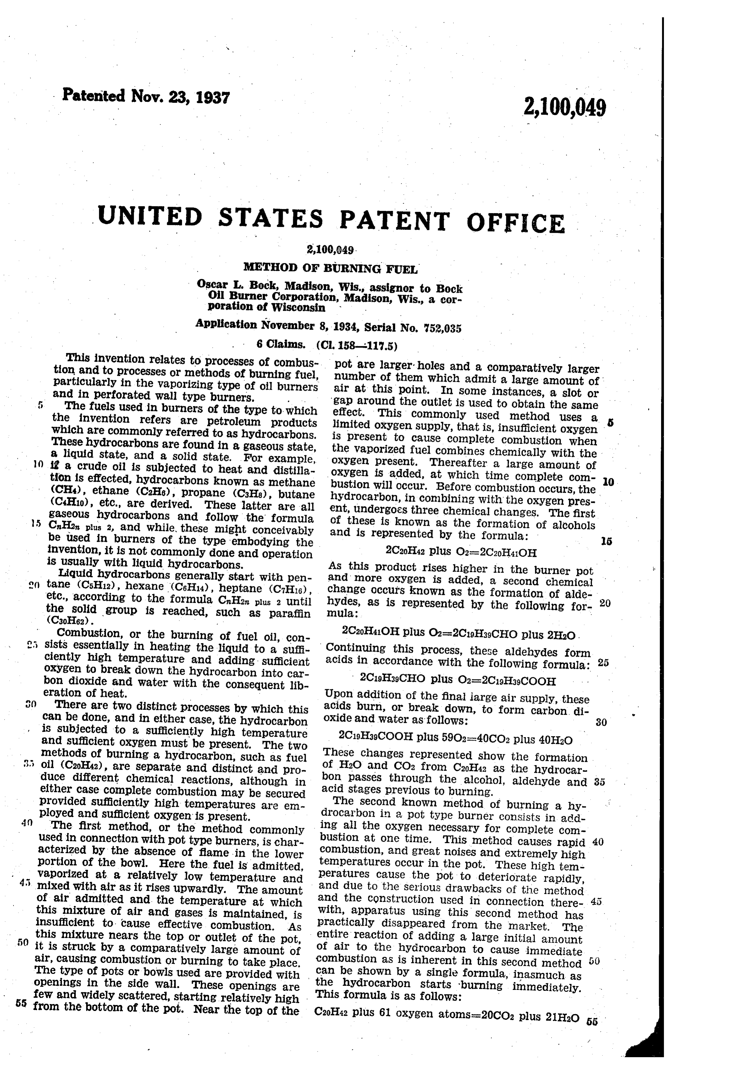
This invention relates to processes of combus pot are larger holes and a comparatively larger tion and to processes or methods of burning fuel, number of them which admit a large amount of particularly in the vaporizing type of oil burners air at this point. In some instances, a slot or and in perforated Wall type burners.
gap around the Outlet is used to obtain the same
The fuels used in burners of the type to which effect. This commonly used method uses a the invention refers are petroleum products limited oxygen supply, that is, insufficient oxygen which are commonly referred to as hydrocarbons. is present to cause complete combustion when These hydrocarbons are found in a gaseous state, the vaporized fuel combines chemically with the a liquid state, and a solid state. For example, oxygen present. Thereafter a large amount of 10 is a crude oil is subjected to heat and distilla- oxygen is added, at which time complete com tion is effected, hydrocarbons known as methane bustion will occur. Before combustion occurs, the (CH4), ethane (C2H6), propane (C3H8), butane hydrocarbon, in combining with the oxygen pres (C4H10), etc., are derived. These latter are all ent, undergoes three chemical changes. The first gaseous hydrocarbons and follow the formula of these is known as the formation of alcohols 15 CnH2n, plus 2, and while, these might conceivably and is represented by the- formula: be used in burners of the type embodying the
invention, it is not commonly done and operation 2C20H42 plus O2=2C20H410H is usually with liquid hydrocarbons. As this product rises higher in the burner pot Liquid hydrocarbons generally start with pen- and more oxygen is added, a Second chemical on tane (C5H12), hexane (C6H14), heptane (C7H16), change occurs known as the formation of alde etc., solid the according to the formula CHausa until hydes, as is represented by the following for- ' group is reached, such as paraffin mula:
(C3oE62). -
Combustion, or the burning of fuel oil, con- 2C-HaOH plus O2=2C19H29CHO plus 2H2O. 25 sists essentially in heating the liquid to a suffi- Continuing this process, these aldehydes form ciently high temperature and adding sufficient acids in accordance with the following formula: 25 Oxygen to break down the hydrocarbon into car- 2C19H29CHO plus O2=2C19H29COOH bon dioxide and water with the consequent lib- o eration of heat. Upon addition of the final iarge air supply, these to can here are two be done, and distinct in eitherprocesses case, thebyhydrocarbon which this acids burn,water oxide and or breakdown, as follows: to form carbon di 30 is subjected to a sufficiently high temperature 2C19H29COOH plus 5902-40CO2 plus 40H2O E.E.T. E. These changes represented show the formation 35 oil (C20HA2), are separate and distinct and pro- S. H2O S. El CE the hydrocar- 35 duce different chemical reactions, although in E. roug t l alcohol, aldehyde and 35 either case complete combustion may be secured act ages Ey. O "of burni h provided ployed andsufficiently high temperatures sufficient oxygen is present. are em- test, odorconsists on in a pot type burner burninginaadd
4) The first method, or the method commonly ling all the oxygen necessary for complete com used in connection with pot type burners, is char- bustion at one time. This method causes rapid 40 acterized by the absence of flame in the lower combustion, and great noises and extremely high if hower the fiel's imit. Eleo.T.S.E.E.
vaporized at a relatively low temperature and peratures cause the pot to deteriorate rapidly, withiasirises upwardy. The amount SESS.E. "Shod edieu Wii at the Construction usin Conectionee 45 this mixture of air and gases is maintained, is Act, SE"E.E. t send ad i o p C a. On the naket. e E.se: E". p. entire reaction of adding a large initial amount
it iscausing strick combustion by comparatively largeto take or burning amountplace.of EEEEEEEE,
The type of pots or bowls used are provided with , s shown by a single formula, inasmuch as openings in the side wall. These openings are e hydrocarbon fit burning immediately. few and widely scattered, starting relatively high This formula is as follows: 55 from the bottom of the pot. Near the top of the C20H42 plus 61 oxygen atoms=20CO2 plus 21H2O 55
Page 3
This shows the formation of HaO and CO2 from burner including slight modifications in arrange Caohai as the hydrocarbon passes directly through is ment of the parts. is the process of burning. In the present construction a perforated wall The differences between the two methods, the type of pot is used. The openings start rela Construction of the burner equipment, and the tively close to the bottom and are of such size 5 type of flames produced are apparent even to the as to admit only sufficient air to cause active most uninitiated. combustion to occur in the bottom of the pot, or, The present invention utilizes Certain preferred in other words, at the point of vaporization. Ad elements and characteristics relating to the ditional holes are provided along the side walls of the pot above the lower openings, and these 10 burner construction as set forth in the first additional 0. method, but employs certain principles of the numbers asholes are of such size and in such to add air progressively to the burn method of burning as related in the second method. In other words, the second method of ing mixture so that sufficient air for complete burning fuel oil with certain modifications, is combustion has been added when the top or upper row of holes is reached. The lower holes 5 used in connection with certain preferred modi directly adjacent to the bottom of the pot are of fications of perforated wall pot-type of burner as greatest set forth in the first method. importance and the amount of air which An important object of the present invention they admit determines the temperature in the is to provide a burner which utilizes advantages Vaporizing area. The greater the amount of air 20 of the methods and apparatus used in the two admitted at this point, the more complete will 20 aforesaid methods, and which eliminates the dis be the combustion at the bottom of the pot and consequently the higher will be the temperatures advantages inherent to those methods.
Another object of the invention is to provide at this point. If these holes are relatively large, an oil burner of the pot type which is provided the temperatures will rise higher than is neces Sary. Also if these holes are made excessively 25 with openings in the wall thereof, said openings large being of a sufficient size to permit entry of suffi the noise of combustion will become notice cient air to allow partial combustion of the fuel able. It is, therefore, important that these holes be of proper size so that only sufficient air is to occur at the bottom of the pot, the burner allowed to enter to cause active combustion to having additional openings in the Wall to admit 30 air sufficient to complete the process of combus start. Air is then added progressively through 30 tion; and which is constructed and arranged SO the remaining holes in the side walls of the pot that the temperature in the bottom of the pot, as the burning mixture rises upwardly so as to during normal operation of the burner, is higher complete the process of burning. Tests show than the endpoint of any of the fuels used. that by varying the lower row of holes any de 35 Another object of the invention is to provide sired temperature in the vaporizing area can be a burner of practically noiseless operation and . Secured. For practical purposes it has been de which, during operation, permits a flame to burn termined that approximately 1100 F. is ample to completely vaporize any of the fuels com upwardly from the bottom of the pot.
A further object of the invention is to provide monly used for domestic heating purposes and 40 a process of burning relatively heavy fuel oils yet prevent disturbing noises from occurring. 4) without the formation of excess residual carbon Typical burner designs. embodying the above and coking, and which is not limited to the lighter principles, and which have been found very Sat fuels, such as kerosene, range oil and distillate as isfactory in commercial use comprise a suitable Outer casing or jacket S mounted on a Suitable recommended in conventional methods.
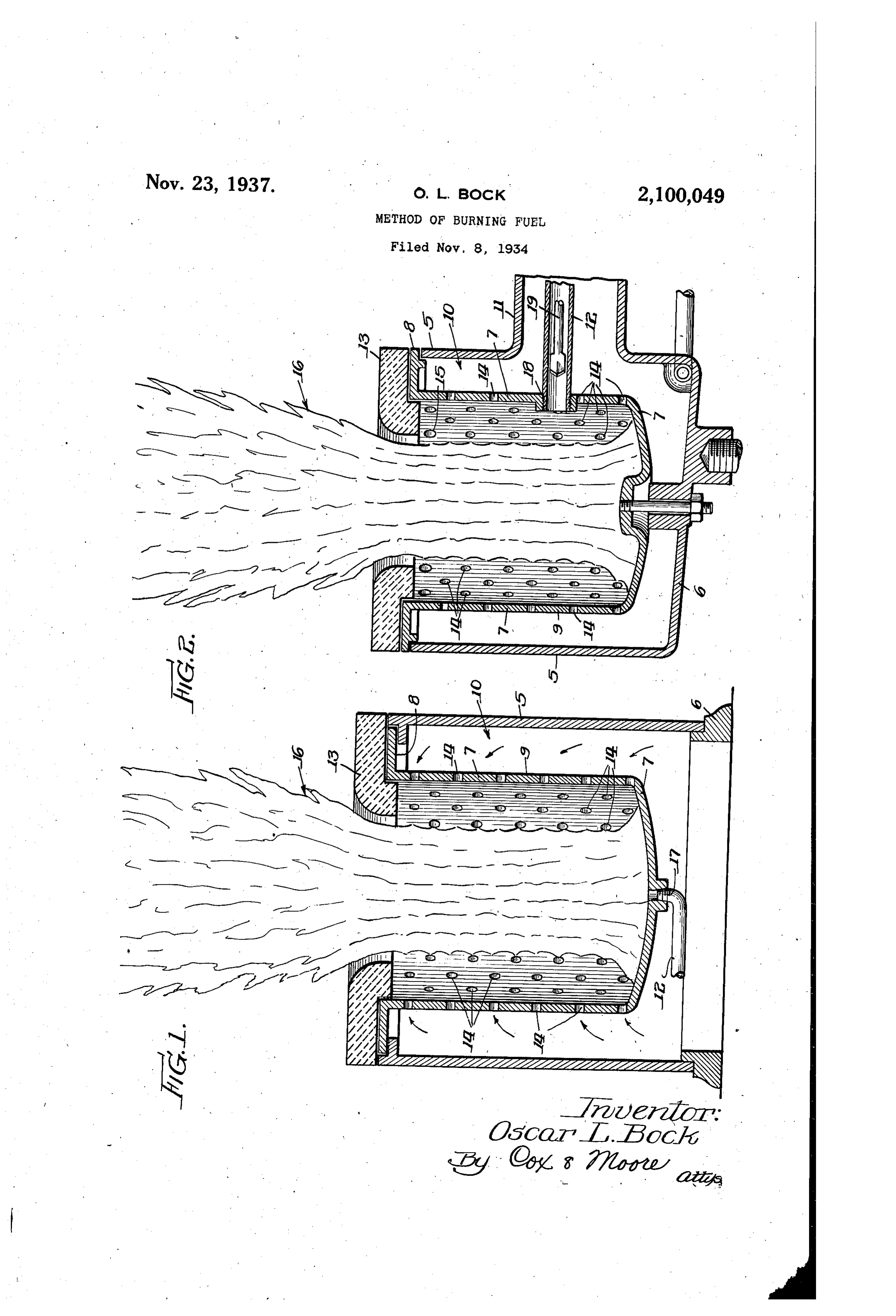
45 Still another object of the invention is to pro supporting base 6. A burner bowl or pot having vide a process for maintaining a normal operating an exteriorly positioned annular flange 8 is Sup temperature in the pot which is beyond that re ported by the outer surrounding side walls of the quired to vaporize the heaviest hydrocarbon pres jacket 5. The surrounding walls 9 of the bowl ent, adding sufficient air so that combustion oc or pot are Spaced a predetermined distance 50 curs immediately as the hydrocarbon is vaporized, from the surrounding jacket or casing 5 to pro and then adding additional air so that complete vide a Space, or air passage fo, which may COn combustion of all the fractions of the hydrocar pletely surround the bowl 7. Air is supplied to bons will occur at the rate at which fuel is being the passage to through the duct i?, and a fuel supplied to the combustion bowl. inlet 2 supplies the liquid hydrocarbon to the 55 The process consists generally in introducing interior or combustion chamber of the bowl. hydrocarbon fuel into a vaporizing Zone, main A refractory ring 3, preferably made of ceramic taining said Zone during normal Operation at Such material, is arranged above the burner and over a temperature that vaporization of lighter hydro hangs the bowl 7 at its upper end as clearly shown carbons and heavier hydrocarbons occurs simul in the drawing. A plurality of relatively large taneously, mixing the hydrocarbons with a suffi holes 4 are made in the walls of the bowl 7, and 60 60 cient amount of atmospheric oxygen at the point these openings 4 may be larger and greater in of vaporization to maintain Such a temperature, number than the conventional arrangement now and supplying additional oxygen progressively to in use. The holes 4 may be carried down the complete the process of burning whereby excess side of the bowl to a point just above the bottom 65 carbon and coke formations will be practically Of the bowl. Air entering the lower holes or eliminated. Openings blows directly across the top of the Numerous other objects and advantages will liquid hydrocarbon and causes initiation of com be apparent throughout the progress of the foll bustion to occur at that point. As the flame in lowing specification. the bowl rises, additional air is supplied pro 70 The accompanying drawing illustrates a Se gressively in sufficient quantity to complete the 70 lected embodiment of the invention and the process of burning. In Fig. 2 the holes in the views therein are as follows: uppermost row are shown larger, as indicated at Fig. 1 is a detail vertical Sectional view through 5, whereby it is possible to shorten the height one form of burner embodying the invention. of the bowl.
75 Fig. 2 is a similar view of a similar type of The characteristic flame of a burner having
Page 4
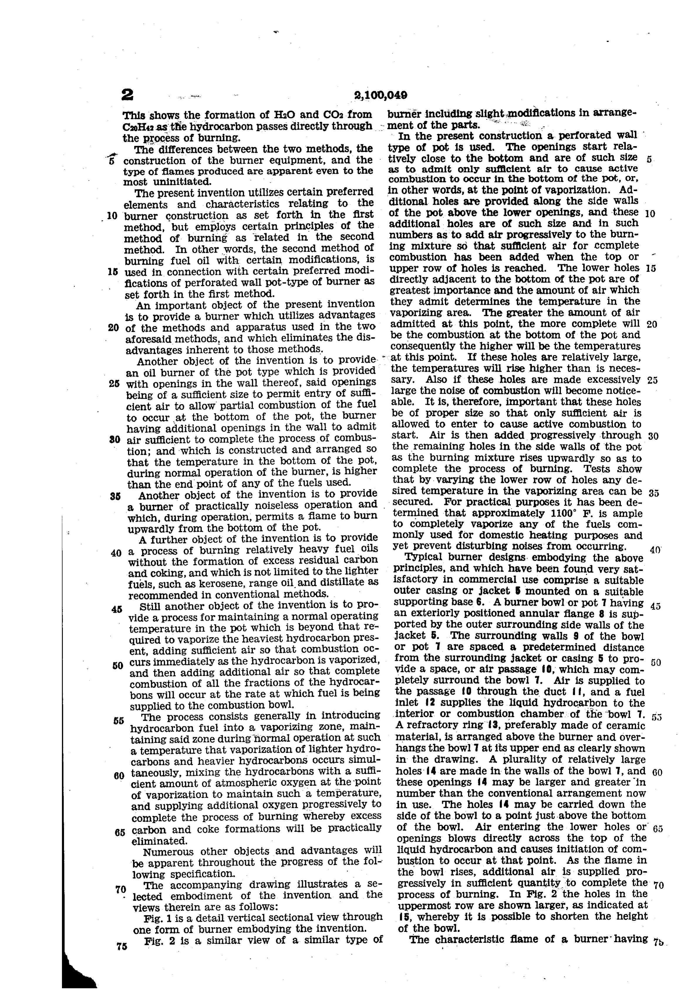
the type of bowl in accordance with the present means of the additional openings in the side wall invention is long and narrow as indicated at . of the bowl to complete the process of burning. The flame starts from the bottom of the bowl It is, therefore, a fundamental principle of the and is spaced from the side walls thereof, pass present invention that the temperature in the 'ing up through the center opening to a maximum vaporizing area during normal operation be at height of probably several times the depth of all times higher than the end point of the fuel the bowl. The amount of oil capable of being being burned with sufficient oxygen at the point burned in a given size bowl is several times asof initiation of vaporization to cause immediate great as in conventional burners, depending of
O course, upon the temperatures in the vaporizing burning without the formation of the various gaseous compounds which are formed in the suc O.
area during normal operation. For example, a standard 8-inch bowl of the conventional low cessive intermediate steps previously described in connection with the conventional process. In temperature type of burner, such as is obtain able on the open market, is rated by the manu other words, this is a direct process of burning, 5 facturer as having a maximum burning capacity whereas the conventional might be termed indi rect. This relatively higher vaporizing tempera of one quart an hour; while an 8-inch burner of ture is determined by the holes 4 in the burner 5 the type made in accordance with the present invention has a capacity of eight quarts of oil side walls, the location of the holes, and the num berthereof. By increasing the size of the holes per hour. The average rate of vaporization in 4 and placing them closer together, as well as 20 the conventional low temperature types of burn keeping them close to the bottom of the bowl, ers as set forth in the two known methods is ap the vaporizing temperature can be increased. It 20 proximately 60th of a quart per hour per square is well known that any petroleum product or by inch of vaporizing surface as compared to ap product will completely burn if vaporized at a proximately 6th of a quart per hour in the pres sufficiently high temperature and given enough ent new high temperature type of burner. oxygen, with the exception of the mineral deposits The exact temperature at which the bottom of found present. Actual tests made with crude oil, 25 the fire bowl or pot should be maintained is im hard carbon (or coke) formations, and tar, show portant, and, of course, this temperature will these materials capable of burning completely, depend on the fuel to be burned. In any event except for a few fine minerals which form mineral the temperature in the vaporizing area must be ash and which are usually so light that the air 30 kept higher, during normal operation, than the currents cause them to be blown away. end point of the fuel used because such tempera As previously set forth, the present invention ture is essential if continuous Operation is to be. is not limited to the lighter fuels, such as kero had without the formation of residue. Fuel oil Sene, range oil, and distillate, but includes the #2, American Oil Burner Association specifica heavier fuels. If the principles of the present tion, sets forth the minimum flash point as be invention are adhered to, and a burner is designed ing 125° F.; the maximum flash point 190° F.; for the particular fuel intended, in accordance and the 10% point 440° F.; the 90% point 620 with the present invention, the heavier fuel will F., and the end point as 660 F. In order to become completely burned.
4) completely burn this fuel, it is essential that In certain tests it was found necessary to main temperature in excess of 660 F. be maintained tain vaporizing temperatures as high as 1600°F, 40 in the vaporizing area during continued normal but these very high temperatures cause rapid operation. r deterioration of the bowl and in some cases crack If the temperature in the vaporizing area is the walls of the bowls, therefore necessitating 45 kept below 660 F., a portion of the fuel will re replacement. Also, if the size of the openings is main unvaporized, and if operation is continued too greatly increased, the noise of combustion indefinitely under these conditions, unvaporized would likewise greatly increase. However, for fuel will accumulate and as the heavier ends practical purposes it has been found that a va become heated in an insufficient amount of air porizing temperature of 100° F will burn #1, 50 for complete combustion, residual carbon or coke #2 or #3 oils of the American Oil Burner Asso will be formed. In a similar manner if a buriaer ciation specification with entire satisfaction with is operated under forced conditions, that is, for out in any way causing deterioration of the bowl long periods of time at a high percentage of its or increasing the noise of combuston. Tests have maximum burning capacity, the reflected heat proven that the life of the burner bowl is indefi 55 of the flame causes the temperatures within the nite, when the vaporizing temperature of the bowl to increase substantially. Waporization bowl is approximately 1100 F. This tempera would then occur at a rapid rate and without ture is sufficiently beyond the end point of these increase in the amount of oxygen being supplied fuels to give complete vaporization and yet pre to the lower portion of the bowl, leaving it with vent excess noise of combustion. Deterioration 60 out sufficient oxygen to cause burning. Under and shortening of the life of the bowl is prevented 60 these latter conditions temperatures in the vapor if this temperature is not exceeded. izing area will become sufficient to break down A practical illustration, to further explain the the hydrocarbon, with the formation of coke. invention, was made with a combustion bowl five Therefore, in order to have continuous normal 65 operation without the accumulation of residual (5) inches in diameter and six (6) inches deep. formations in the vaporizing area of the bowl, it The lower row of openings, or the initial air 65 Supply, consisted of a band of holes .136 of an is essential to have temperatures in this area in inch in diameter spaced on 3% inch centers and excess of the end point of the fuel being burned, located 6 of an inch from the bottom of the so that the fuel will become completely vaporized, pot. The remaining holes throughout the bal 70 and sufficient oxygen must be present at the iniance of the pot were .113 of an inch in diameter, starting one inch above the initial row and spaced 70 tiation of vaporization to cause active combustion to occur at the point of vaporization, and at any rate of vaporization within the capacity of the on half-inch centers with each succeeding row
bowl. When such is the case and the flame rises The particular construction just described s in the bowl, further oxygen may be added by shows a normal operating temperature when op
Page 5
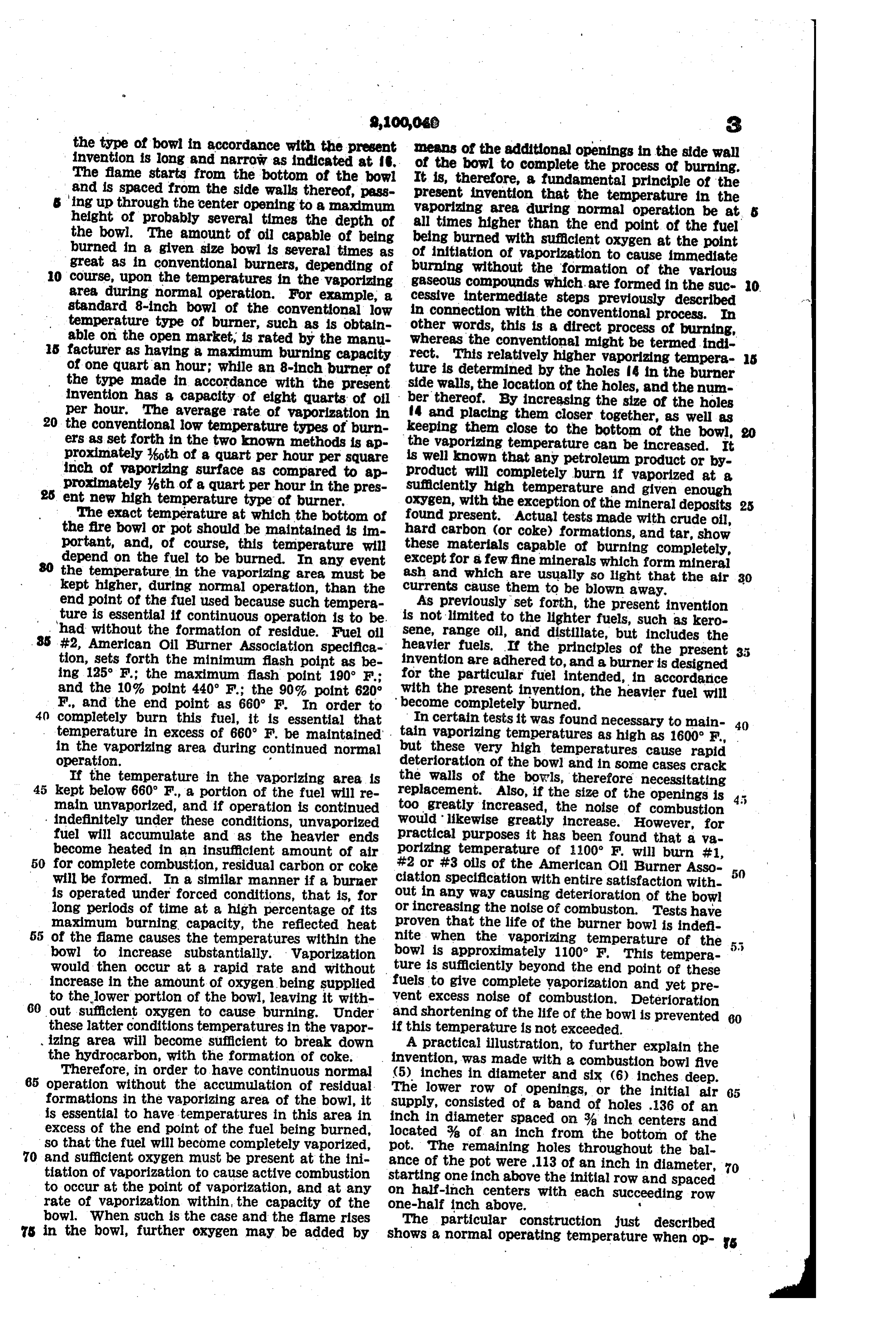
erating at aproximately its maximum output of erating temperatures higher than the end point 1100 F. at various points in the vaporizing area, of the fuel supplied, and inasmuch as the fuel is and that it is capable of successfully burning oil vaporized as rapidly as it is being admitted, no of extremely low gravity and high end point. residual fuel will remain in the bowl. Also, all The actual combustion occurs slowly and is ex fractions of the fuel will be distilled at the same tremely quiet. It is impossible to form carbon time and this condition exists as long as fuel under any reasonable adjustment inasmuch as is being supplied in amounts within the vaporiz sufficient air is admitted in the lower row of holes ing capacity of the particular bowl used. In to cause initiation of combustion at this point, other words, distillation of the lighter ends fol 10 avoiding the possibility of decomposing the fuel lowed by the heavier ends is not occurring, but 0. in an insufficient supply of oxygen with the re all fractions of the fuels are being volatilized at suitant formation of carbon. once. The present process, therefore, may be It is apparent that this construction can be distinguished from others by the fact that all altered and still cause combustion to occur as the fractions of the hydrocarbons are burned above described. For example, instead of the coincidentally.
lower row of openings consisting of a row of holes By a temperature above the "end point' is of 136 inch in diameter, two rows of holes form meant to define such a temperature in the fire ing the same total opening might be employed pot and particularly in the zone where the oil and give practically identical results. Likewise, is added as would cause the continuous vaporiza the remaining holes could be changed without tion of substantially all the fractions of the oil 20 necessarily changing the results. as they are added.
Bowls of larger or smaller diameters, depend Many of the so-called fuel oils now being ing upon the amount of fuel to be burned per supplied are blends or mixtures of a relatively hour, may have the sizes of the holes, spacing light volatile fuel and heavier fuel So as to 2 5 and arrangement thereof proportioned accord produce a resultant fuel of the gravity desired. 25 ingly. The mixing or blending of the various oils causes Tests with a thermocouple placed at various certain difficulties in the conventional types of points throughout the vaporizing area of a bowl burners because of the heavy hydrocarbons of the size and construction referred to show present. These mixtures or blends are, however, 30 temperature around 1100 F. with the exception readily burned in an apparatus constructed in of that portion directly around the point of oil accordance with the present invention as proven. entrance. At the point of oil entrance a cool by actual practice, because heavier hydrocarbons ing effect is encountered due to the relatively are burned simultaneously with the lighter hy cold oil entering and due to the feed pipe fasten drocarbons as soon as admitted to the burner 35 ing in the bowl tending to conduct heat away bowl.
from the bowl. This relatively cool area cannot The present invention, therefore, eliminates be maintained at temperatures beyond the end many of the disadvantages inherent in the con point of the fuel being burned. Therefore, some ventional modes and methods now used and carbon is likely to accumulate at this point. If causes complete. volatilization of all the frac 40 the fuel inlet to the burner is at the botton tions of the fuel used. 40 fioor of the bowl as indicated at 7 in Fig. 1, Changes may be made in the herein disclosed carbon will eventually cover over the opening process of combustion within certain limits and clog the fuel inlet. If the oil inlet to the without departing from the spirit of the inven bowl is placed in the side wall of the bowl below tion or sacrificing any of the advantages thereof, 45 the lowermost row of holes 4, a slight improve and the right is hereby reserved to make all such 45 ment is obtained as the carbon must first build changes as fairly fall within the Scope of the up over the entire opening before it will be con following claims.
pletely clogged. The arrangement of a rod The invention is hereby claimed as follows: within the feed line to dislodge the carbon would 1. The process of combustion which consists in 50 be of some assistance, but eventually the carbon introducing a liquid fuel into the combustion 50 would form over the path of the rod and com Zone of a burner adjacent the bottom thereof, pletely envelop it and therefore render it ineffec maintaining the bottom of the combustion zone tive. - at a temperature higher than the end point of the By bringing the oil feed line into the side walls liquid fuel introduced during normal operation 55 of the bowl as indicated at 8 in Fig. 2, the of the burner, supplying, sufficient air at the bot 55 carbon area is confined to a point directly over. tom of the Zone to cause the liquid fuel to burn the oil inlet and immediately surrounding it, at such rate at the bottom of the zone as to main leaving the bottom of the bowl free and clear tain said temperature thereof, and finally adding of any accumulation. By localizing this car additional air progressively toward the top of 60 bonizing effect, the carbon may be dislodged by the Zone to allow complete combustion. 60 means of a rod 9, Fig. 2, inserted in the feed 2. The process of combustion which consists in line. The dislodged carbon formation, which vaporizing liquid hydrocarbon fuel at a tempera will only occur directly over the end of the feed ture higher than the end point of the hydrocar line, will drop to the bottom of the bowl wherebon, mixing sufficient air at the point of vapori 65 it will be struck by the incoming jets of air in Zation with the hydrocarbon fuel vapor to cause 65 the lowermost row of holes and be subjected to initiation of combustion and to cause such tem the heat of combustion causing it to be burned. perature to be maintained, and admitting air By this arrangement the entire vaporizing area progressively to the burning hydrocarbon fuel in the bottom of the bowl is maintained at a vapor after initiation of combustion to complete 70 uniformly high temperature. The location of the combustion of the fuel vapor. 70 the feed line in the side Wall of the bowl. With 3. The method of burning a liquid hydrocar the air openings completely surrounding it, bon fuel which comprises introducing the liquid causes the carbon formation to localize, leaving hydrocarbon fuel into the bottom of a combustion the vaporizing area free and clear. Space and Supplying air to the bottom of said 75 The present invention provides for normal op space in amount sufficiently restricted to cause 76
Page 6
a portion only of the hydrocarbon fuel to burn of all of the fractions of the hydrocarbon fuel, Substantially at the bottom of the space, main-. mixing a restricted quantity of air Sufficient to taining the temperature at the bottom of said support combustion of only a portion of the fuel combustion space at a point sufficiently above the vapors therewith at the time of vaporization to 5 end point of the hydrocarbon fuel to cause Con tinuous vaporization of substantially all the frac permit immediate initiation of combustion, als tions of the hydrocarbon fuel, and maintaining lowing the residual vapors to move away from said temperature by the combustion of said fuel. the point of vaporization, and admitting addi tional air progressively to the burning hydrocar 4. The process of combustion which consists bon fuel vapor as it moves to complete combus 10 in introducing a liquid hydrocarbon fuel into an tion, and maintaining said temperature by Com 0. upstanding combustion space of a burner at the bustion of the fuel.
bottom of said space, maintaining the bottom of 6. The process of combustion which consists in said combustion space at a temperature higher introducing a liquid hydrocarbon fuel into one than the end point of the hydrocarbon fuel end of a combustion space, introducing into said 5 whereby to vaporize all fractions of the fuel, Sup plying sufficient air only at the bottom of the space adjacent the place of fuel introduction suf Space to cause the hydrocarbon fuel to burn Sub ficient air to vaporize said fuel at a temperature higher than its end point by combustion of a stantially at the bottom of said space, the air portion of the fuel vapor sufficient to cause said being in a quantity restricted sufficiently to per temperature to be maintained, and afterward 20 mit burning of only a portion of the fuel Vapor.
introducing additional air progressively into said 20 5. The process of combustion which consists in combustion space to complete combustion of the vaporizing a liquid hydrocarbon fuel at a tem fuel vapor.
perature sufficiently higher than the end point OSCAR, L, BOCK. . to cause substantially simultaneous vaporization
Provenance
- Collection
- Cited prior art
- Original PDF
- patentimages.storage.googleapis.com →
- Filed
- 1934-11-08
- Pages
- 6
- Method
- pdftotext (the PDF's own text layer) + pdftoppm 300dpi page scans
- Source
- Google Patents bibliographic record
- Granted
- 1937-11-23
- Inventors
- Oscar L Bock; BOCK OIL BURNER CORP
- Transcribed from
- patentimages.storage.googleapis.com →