patent · US2339637
Pot type burner with double baffle structure
18 January 1944
Page 1
Drawing sheet — no readable text.
Page 2
Jan. 18, 1944. B, HAYTER 2,339,637
POT TYPE BURNER WITH DOUBLE BAFFLE STRUCTURE
SNS 000osose 6 6 6 s s s es pe e e 0 edged Goodoo
E. z zii ava Aviv
Yasas
Taxaawa YAYYA
seawee y2
Sassessessessee 4. NS ava
Page 3
POT TYPE BURNER wTHDoUBLE BAFFLE
STRUCTURE
Bruce Hayter, Santa Fe, N. Mex, assignor to Oil
Devices, Santa Fe, N. Mex, a limited partner ship of Illinois
Application March 14, 1942, serial No. 434,662
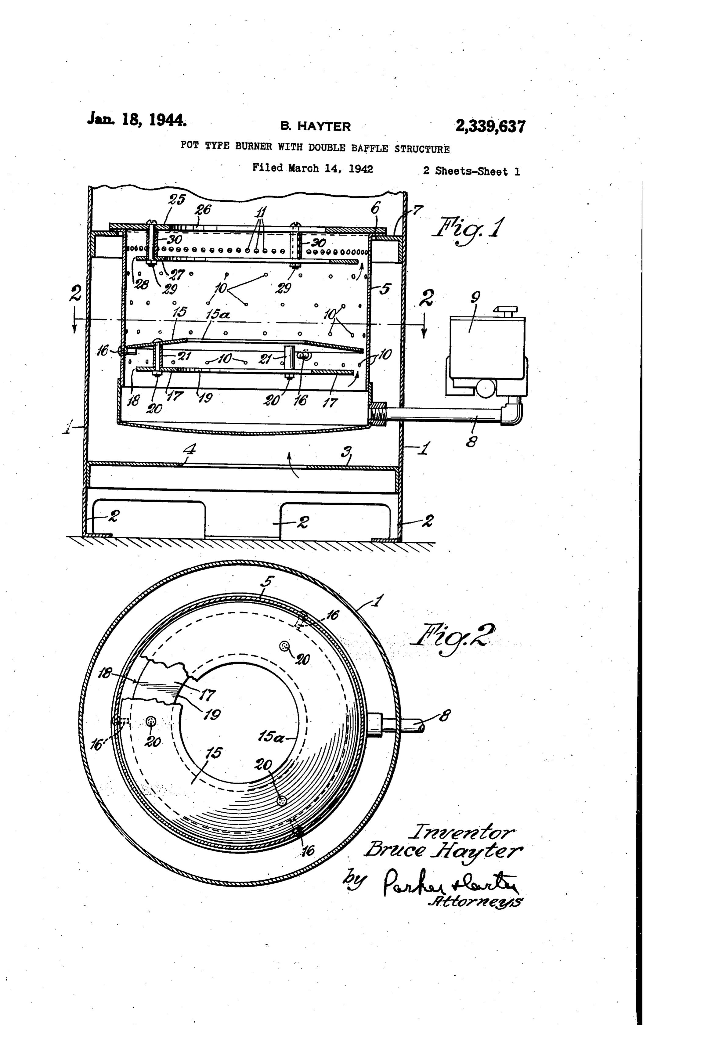
My invention relates to an improvement in pot of secondary air inlet apertures f, which are type oil burners and has for one purpose to preferably upwardly and inwardly tilted and provide an improved burner in which a cleaner which are larger or more closely spaced than flame is produced. the primary air inlet apertures 0, or both. Another purpose is to provide an improved 5 indicates a pilot baffle centrally apertured baffle structure for such burner. as at 5a and positioned intermediate the upper Another purpose is to provide an improved pilot and lower primary inlets 0. I. illustrate it, for structure or pilot baffle. example, as located above the lowest row of ap Another purpose is to provide improved baffle ertures. 0. It may be mounted on pins 6 or structures for pot type burners which provide 10 any other suitable securing means. Positioned recirculation of the vaporized fuel and assist in below the lowest air inlet apertures to I provide mixing the vaporized fuel and the inflowing air. a supplemental or recirculating ring 7, the outer Other purposes will appear from time to time edge of which is spaced inwardly, as at 8, a in the course of the specification. substantial distance from the opposed inner wall, I illustrate my invention more or less diagram 15 of the pot 5. The baffle 7 has a central aper matically in the accompanying drawings where
ture f axially aligned with the central aperture 6a of the pilot baffle 5, and is herein shown as
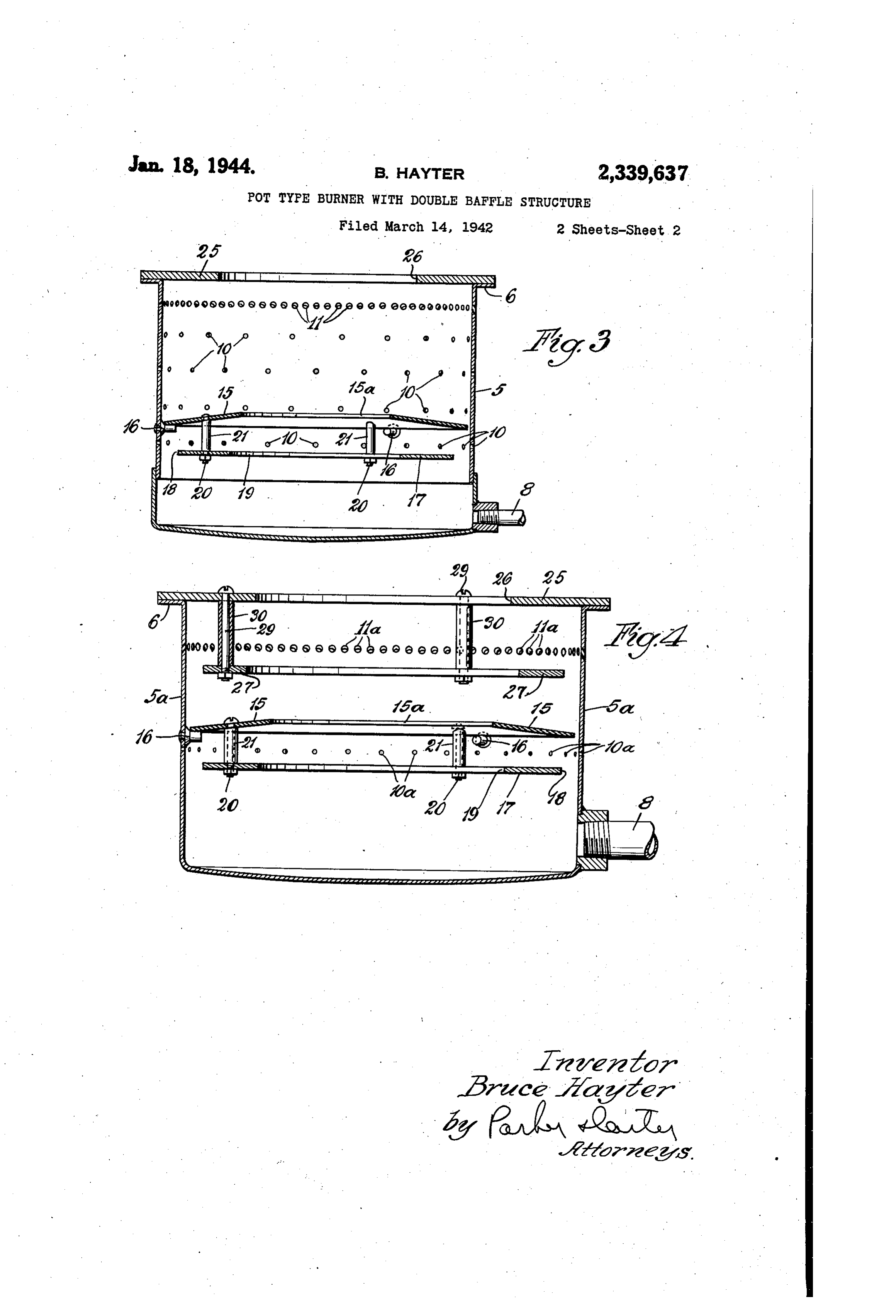
Fig. 1 is a vertical axial section; of somewhat greater diameter. The baffle T is Fig. 2 is a section on the line 2-2 of Fig. 1; preferably supported upon or suspended from the Fig. 3 is a vertical axial section illustrating a baffle 5, for example by bolts 20 and spacing variant form of the device; and sleeves 2. Thus the pilot structure, including. Fig. 4 is a vertical axial section illustrating a both rings, may be unitarily inserted into or ree still further variant of the device. moved from the pot. The pins may be of such 3: Like parts are indicated by like symbols length as to permit the ready passage therebes . throughout the specification and drawings. tween of the ring fl. . Referring first to the form of Figs. 1 and 2, Located at the top of the pot 5 and partially generally indicates an outer housing, which may closing it is a flamering 25 having a central ap be of any suitable size, shape and proportion, erture 26. It will be observed that the secondary. .. but which is herein shown as a generally cylin air inlet apertures are located below the flame drical drum. It may include or have any suitable 30 ring. Located below the fame ring 2 is the rea ... . supporting members 2, which space the lower circulating ring 27, which, like the lower reciras . edge of the drum above the floor or surface upon culating ring 7, is of such diameter that there . which the heater is positioned. 3 is a lower par is a substantial gap between its outer edge 28 and tition having a central air inlet aperture 4. 5 the inner face of the pot 5. It may be sus indicates a burner pot which has an outwardly 35 pended from or mounted on the flame ring. 2, . extending top flange 6, which may rest upon any as by bolts 29 and spacing sleeves, so that suitable annular support 7 inwardly extending it may also be removed from the pot unitarily from the wall of the housing f. with the fame ring 25.
8 is any suitable fuel pipe, the flow of fuel along As shown in Fig. 3, the upper recirculating ring which may be controlled in any suitable man 40 27 may be omitted, and the flame ring 25 is shown ner, for example by the float structure generally as without any depending supporting structure. shown at 9, the details of which do not form Referring to Fig. 4, I illustrate a variant form part of the present invention. It will be under of the device in which in the pot 5a, a single row stood that the rate of flow of liquid fuel inward 45 of primary air inlets Oa is employed, and a single ly along the pipe 8 to the bottom of the pot may row of secondary air inlets fia. The pilot struc be regulated manually or automatically, whereby ture, which may be identical with that shown the desired supply of fuel is delivered to the pot. in Fig. 1 and is similarly numbered, is located Preferably the control device is operated so as to at the level of the single row of primary air in maintain at all times at least a minimum flow of 50 lets foa, the pilot f is being above that row and fuel sufficient to maintain a pilot flame. the recirculating ring being below it. Sini The wall of the pot 5 is provided with a plu larly, the flame ring 25 and the recirculating ring rality of primary air inlet apertures (0. Any 2 are located, respectively, above and below the suitable means may be provided for providing a secondary air inlet apertures fla. - secondary air supply at or adjacent the top of The structure of Figures 3 and 4 may be used the pot S. I illustrate, however, a single top row with a housing and valve as shown by Figure,
Page 4
2 - a,389,087
It will be realized that, whereas it have de same is, of course, true of the form of ra. 4. I find it highly desirable to recirculate the scribed and illustrated a practical and operative gases at the pilot stage, or at the high fire stage. device, nevertheless many changes may be made or both.
in the size, shape, number and disposition of parts 5 and betterThe result, is stabilized combustion mixing of the fuel, and a great re without departing from the spirit of my invene. duction in the tendency to form carbon. A quiet tion. I therefore wish my description and draw ings to be taken as in a broad sense illustrative er fire is also provided.
, or diagrammatic, rather than as limiting me to 1. In a pot type burner, a burner pot having . . my precise showing. O a generally cylindrical wall with a plurality of It will be understood also that when in the air inlet apertures therein, means for supply specification or claims I speak of the top of the ing liquid fuel to the interior of the pot, a cen pot, I mean the open mouth of the pot. When
I speak of one part being below another, use atrally apertured ring mounted on said pot, and centrally apertured recirculating ring located . .
the term in relation to the relative distance of 5 in said pot, adjacent said first mentioned ring, the various parts from the open mouth of the said rings overlapping and defining, between The use and operation of my invention are ‘ular them, a recirculating area generally perpendic to the axis of, the pot, the outer diameter of as follows: the recirculating
All the forms of the present device illustrate than that of the first ring being substantially, less the multiple ring or bafe structures including an edge being spaced substantially mentioned ring, its outer . upper ring and a lower ring, which may for con- - the wall of the pot. . inwardly from venience be suspended from the upper ring. ' . .. Thus, 2 is suspended from 2, and 7 from . 2. In a pot type burner, a burner pot having a generally cylindrical wall with a-plurality of
It will be understood that in the form of either air inlet apertures therein, means for supplying Figs, 1 or , the double ring can be used either 25 liqiud fuel to the interior of the pot, a centrally at the top or at the pilot stage, or at both. In apertured ring mounted on said pot, and a cen Fig. 1 illustrate it located both at the pilot stage trally apertured recirculating ring located in and at the top at the higher fire stage. In g. said pot, adjacent said first mentioned ring, said 3 it is located only at the pilot stage. It will be understood, however, that 30 rings overlapping and defining, between them, a pot, the recirculating ring with either may be form of employed at recirculating passage generally perpendicular to the high stage or at the low stage, or at both. the axis of the pot, the outer diameter of the The rings 7 and 27 each serves a recirculating recirculating ring being substantially less than function, and the gases circulate upwardly about 35 that of the first mentioned ring, its outer edge the outer edge of each ring in response to or in being of the spaced substantially inwardly from the wall pot, the pot wall having secondary air association with the inwardly directed jets of inlet apertures air from the apertures or , or la or fla, liver air into thealigned with and adapted to de space between said rings. . .
Each element is in fact a return gas system. 3. In a pot type burner, a burner pot having . In the operation of the device, and assuming.
that the burner of any of the figures is burning 40 a generally cylindrical circumferential wall, at the pilot stage, the relatively small amount means for delivering a liquid fuel to the interior of fuel delivered by the passage is vaporized of the pot, the wall of the post having primary by the heat of combustion going on above it in air inlet apertures therein, means for supplying the pot. At the pilot stage the combustion is . secondary air to the mixture formed in said pot, taking place at or near the level of the pilot ring a centrally apertured pilot ring located in said 15. The primary air supply for the pilot stage pot intermediate top and bottom thereof, and is directed inwardly through the apertures in above the lowest of the primary air inlet aper a plurality of jets which extend substantially in tures, and a centrally apertured recirculating wardly toward the center of the pot. These jets ring located in said pot below...the lowest row of of fresh air entrain and carry on with them a said primary air inlet apertures, the outside di primary mixture of air and vaporized fuel, which ameter of the recirculating ring being smaller flows upwardly through the gap about the ex- . than the outside diameter of the pilot ring, the terior of the pilot ring T, and then flows in outer edge of the recirculating ring being spaced wardly with and along the jets delivered by the inwardly from the wall of the pot sufficiently to lowest row of apertures, or by the row of provide a substantially, circumferential recircu apertures Oa. Thoroughly mixed air and va: lating passage therebetween. ” porized fuel flows upwardly through the central 4. In a pot type burner, a burner post having a aperture S. of the pilot ring , and in the form generally cylindrical circumferential wall, means of Fig. 1 secondary air is provided by the upper for delivering a liquid fuel to the interior of the apertures O. In the form of Fig. 4 all of the pot, the wall of the pot having primary air inlet. secondary air is delivered through the second apertures therein, means for supplying secondary. ary apertures fla, but in both forms the burner air to the mixture formed in said pot, a con at the pilot stage maintains combustion adja trally apertured pilot ring located in said pot cent the level of the pilot ring .
... The burner is made to burn. St the higher 65 intermediate top and bottom thereof, and above the lowest of the primary air inlet apertures, and stage simply by increasing the rate of flow of fuel a centrally apertured recirculating ring located through the pipe B. At that stage all of the in said pot below the lowest row of said primary apertures D of Fig. 1 then provide a primary air inlet apertures, the outside diameter of the air supply for a mixture, which receives its sec ondary air through the apertures . The re 70 recirculating ring being smaller than the outside circulation then takes place at the top of the pot. recirculating ringpilot diameter of the ring, the outer edge of the being spaced inwardly from the primary mixture being drawn upwardly and the wall of the pot sufficiently to provide a sub outwardly about the outer edge of the ring by . . the jets of air delivered inwardly and gehat is stantially circumferential recirculating passage acticiary airinletsil. This
Page 5
cured to said pilot ring and being unitarily re pot, the wall of the pot having a plurality of movable therewith. primary air inlet apertures, means for supply 5. In a pot type burner, a burner pot having a ing secondary air to the mixture formed in said generally cylindrical circumferential wall, means pot, including a row of secondary air inlet aper for delivering a liquid fuel to the interior of the 5 tures located adjacent the top of the pot, a cen pot, the wall of the pot having a plurality of trally apertured flame ring partially closing the primary air inlet apertures arranged in a single top of the pot and located above said secondary. . row extending about the pot, a centrally aper air inlet apertures and a centrally apertured re tured ring located above said row of holes and 10 circulating ring located below said secondary air a recirculating ring located below said row of inlet apertures, and having an outside diameter holes, the outside diameter of the recirculating substantially less than that of the flame risig, ring being less than the outside diameter of the the outer edge of the recirculating ring being first mentioned centrally apertured ring, the out spaced inwardly from the pot wall sufficiently to er edge of the recirculating ring being spaced provide a substantially circumferential recircu inwardly from the wall of the pot sufficiently 5 lating passage therebetween.
to provide a substantially circumferential recir 8. In a pot type burner, a burner pot having a culating passage therebetween. generally cylindrical circumferential Wall, means 6. In a pot type burner, a burner pot having a for delivering a liquid fuel to the interior of the generally cylindrical circumferential wall, means pot, the wall of the pot, having a plurality of for delivering a liquid fuel to the interior of the primary air inlet apertures, means for supplying pot, the wall of the pot having a plurality of secondary air to the mixture formed in Said pot, primary air inlet apertures arranged in a single including a row of secondary air inlet apertures row extending about the pot, a centrally aper located adjacent the top of the pot, a centrally tured ring located above said row of holes and apertured flame ring partially closing the top of a recirculating ring located below said row of 25 the pot and located above said secondary air holes, the outside diameter of the recirculating inlet apertures and a centrally apertured recricu ring being less than the outside diameter of the lating ring located below said secondary air inlet first mentioned centrally apertured ring, the out apertures, and having an outside diametersubstan er edge of the recirculating ring being spaced tially less than that of the flame ring, the outer inwardly from the wall of the pot sufficiently 30 edge of the recirculating ring being spaced in to provide a substantially circumferential recir wardly from the pot Wall sufficiently to provide culating passage therebetween, said recirculat a substantially circumferential recirculating pas sage therebetween, said recirculating ring being ing ring being secured to said first mentioned secured ring and being unitarily removable therewith. to said flame ring and being initially re . In a pot type burner, a burner pot having a 35 movable therewith.
generally cylindrical circumferential wall, means BRUCEHAYTER. for delivering a liquid fuel to the interior of the
Provenance
- Collection
- Cited prior art
- Original PDF
- patentimages.storage.googleapis.com →
- Filed
- 1942-03-14
- Pages
- 5
- Method
- pdftotext (the PDF's own text layer) + pdftoppm 300dpi page scans
- Source
- Google Patents bibliographic record
- Granted
- 1944-01-18
- Inventors
- Hayter Bruce; OIL DEVICES
- Transcribed from
- patentimages.storage.googleapis.com →