patent · US2855031
Vaporizing oil burner
7 October 1958
Page 1
Drawing sheet — no readable text.
Page 2
Drawing sheet — no readable text.
Page 3
Oct. 7, 1958 J. W. MILLER E. A. 2,855,031
WAPORIZING OIL BURNER
Filed Aug. 24, 1953 6 Sheets-Sheet 3
INVENTORS
John W. Mu Lee 6
Asy feedee/ce 7. StoNEY (3.auvvues.A7 roameys.
Aykal faca.
Page 4
Drawing sheet — no readable text.
Page 5
Drawing sheet — no readable text.
Page 6
Drawing sheet — no readable text.
Page 7
United States Patent Office 2,855,031 Patented Oct. 7, 1958
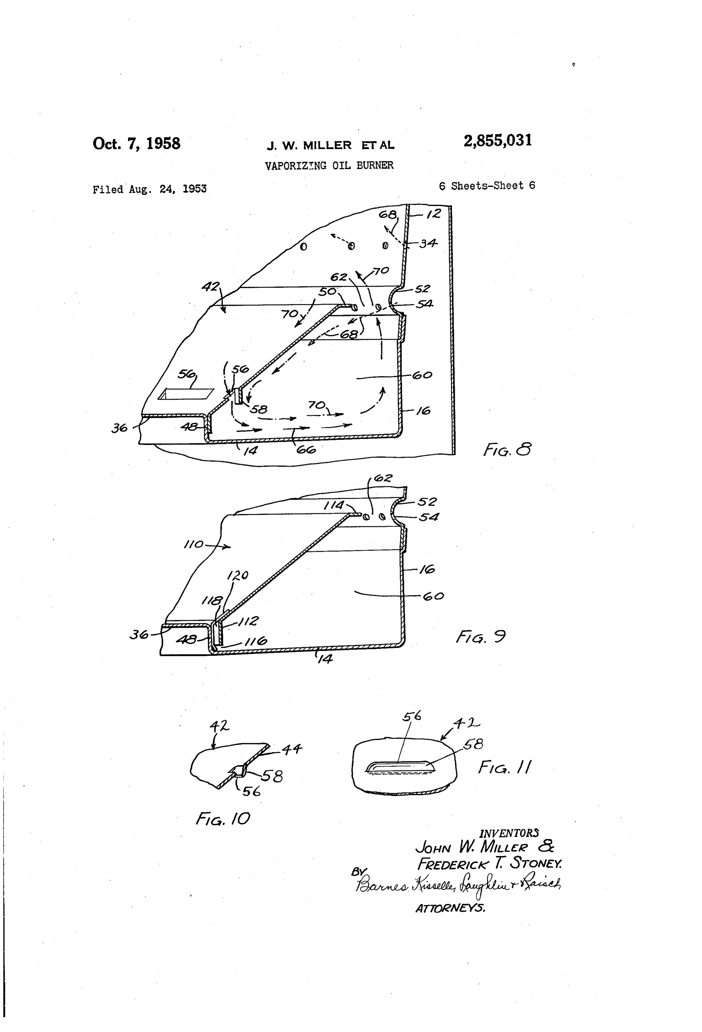
Fig. 11 is a fragmentary elevation of this slot as viewed from the inside of the baffle.
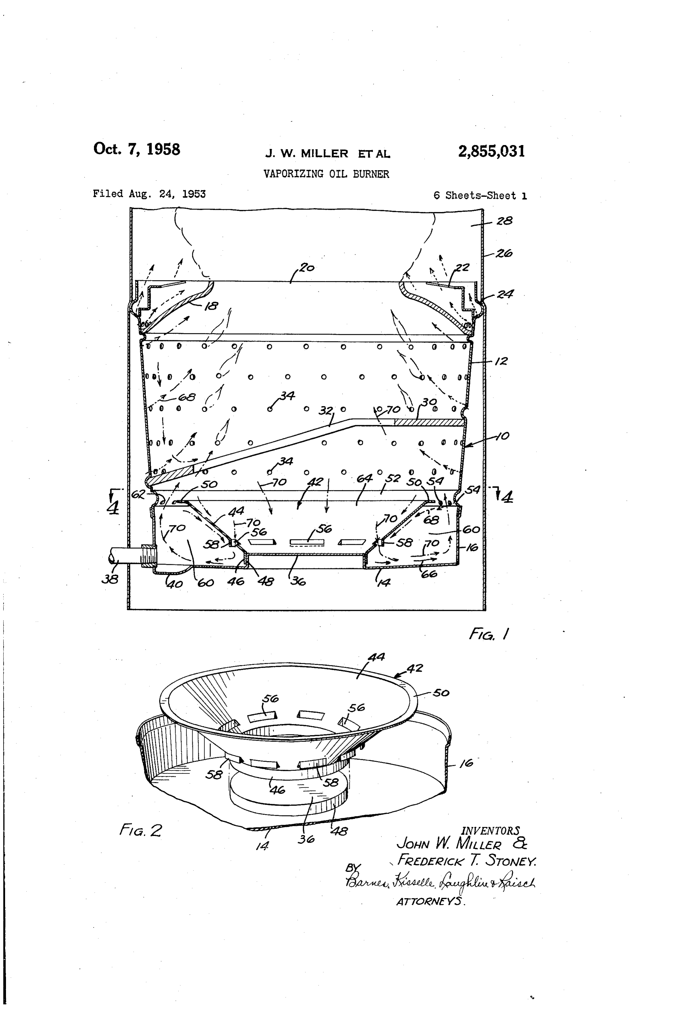
2,855,031 Referring to the drawings and particularly to Fig. 1, a vaporizing type oil burner pot is shown at 10. The
WAPORIZING OL BURNER burner pot 10 comprises two parts, a side wall 12 and a John W. Miller and Frederick T. Stoney, Lansing, Mich., bottom portion which includes bottom wall 14 and assignors to Motor Wheel Corporation, Lansing, Mich., bottom side wall 16. The upper edge of side wall 16 a corporation of Michigan telescopically receives the lower edge of the side wall 12. Adjacent its upper end the burner pot 10 is provided with
Application August 24, 1953, Serial No. 376,094 10 a generally conical top wall 18 having a central open 11 Claims. (C. 158-91) ing 20. An anti-explosion baffle 22 is positioned on top wall 8. An outwardly projecting annular bead 24 is formed adjacent the upper end of side wall 12. The bead 24 has a rather close fit with the skirt 26 which defines
This invention relates to a vaporizing oil burner. 15 a combustion chamber 28 above the burner pot 10. Vaporizing oil burners are old and well known in Within the pot 10 and below top wall 18 there is arranged the art, see, for example, Valjean Patent 2,073,270 and an inclined baffle 30 provided with a central opening 32. the Hill Patent 2,535,923. Side wall 12 is provided with vertically spaced rows of It is an object of this invention to improve upon this air inlet openings 34, some above, and others below, type of vaporizing oil burner so that it will burn with 20 baffle 30.
an unusually clean fire substantially throughout the low, Bottom wall 14 of the burner is generally flat and intermediate, and high fire stages of combustion and also tapers slightly in an inward and downward direction. so that it will burn with a clean fire with any type of The central portion of bottom wall 14 is fashioned with fuel oil on the market today, such as the straight run a raised cylindrical portion 36 which cooperates with distillate fuel oils or catalytically cracked distillate fuel 25 the bottom 14 and side wall 16 to define an annular oils. channel for oil at the base of the burner pot. Oil is ad This invention contemplates a vaporizing type oil mitted to the burner through an inlet 38. In all forms burner that will burn liquid fuel substantially throughout of the burner the oil is supplied to inlet 38 through a the low, intermediate, and high fire stages of operation conventional fuel oil control (not shown) which both with a fire that is substantially cleaner and more efficient 30 meters and maintains the fuel oil at a constant level. Ad than attained heretofore by the vaporizing type oil burn jacent the inlet 38 the bottom wall 14 is formed with a ers of the prior art. depression 40 which provides a sump in which a small The invention generally contemplates a vaporizing body of oil collects, particularly under minimum fire op type oil burner pot in which the fuel is admitted to an eration.
annular channel around the bottom of the pot and caused 35 A baffle 42 is arranged at the bottom of the burner. to vaporize and mix thoroughly with primary air at a Baffle 42 preferably takes the form of an inverted relatively low temperature to form a mixture which flows truncated cone and is provided with an inclined wall 44 upwardly in the pot where secondary air is supplied for which terminates at its lower end in a cylindrical up combustion. A baffle is provided near the bottom of the standing flange 46 having a telescopic tight or close fit burner pot which shields the oil in the annular channel 40 with the cylindrical side wall 48 of the raised central por from direct radiant heat from the burning mixture at the tion 36 of the bottom wall 4 of the burner. Inclined upper end of the pot. This baffle is arranged with re wall 44 of baffle 42 is provided around its upper edge spect to the lower primary air inlets so as to promote with an annular horizontal flange 50.
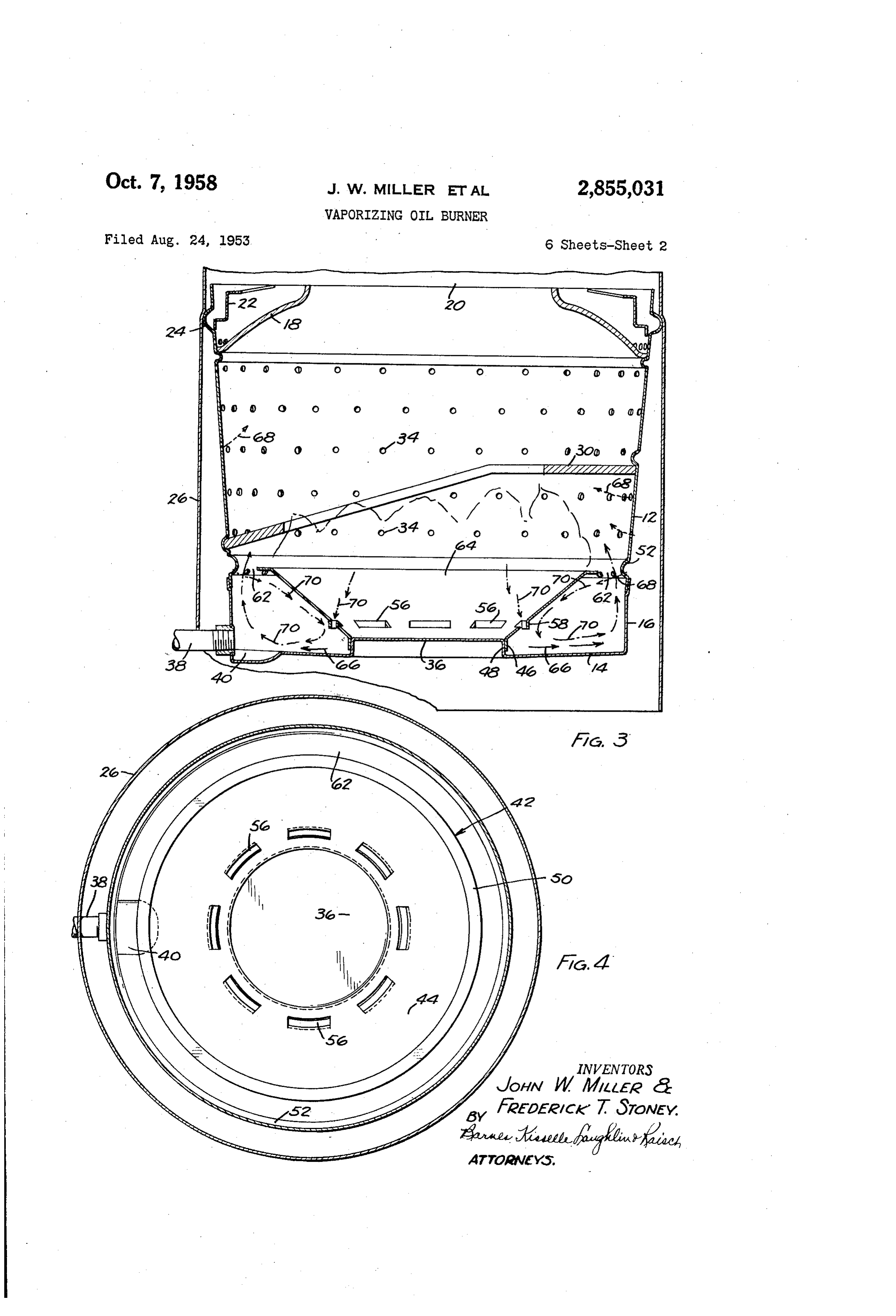
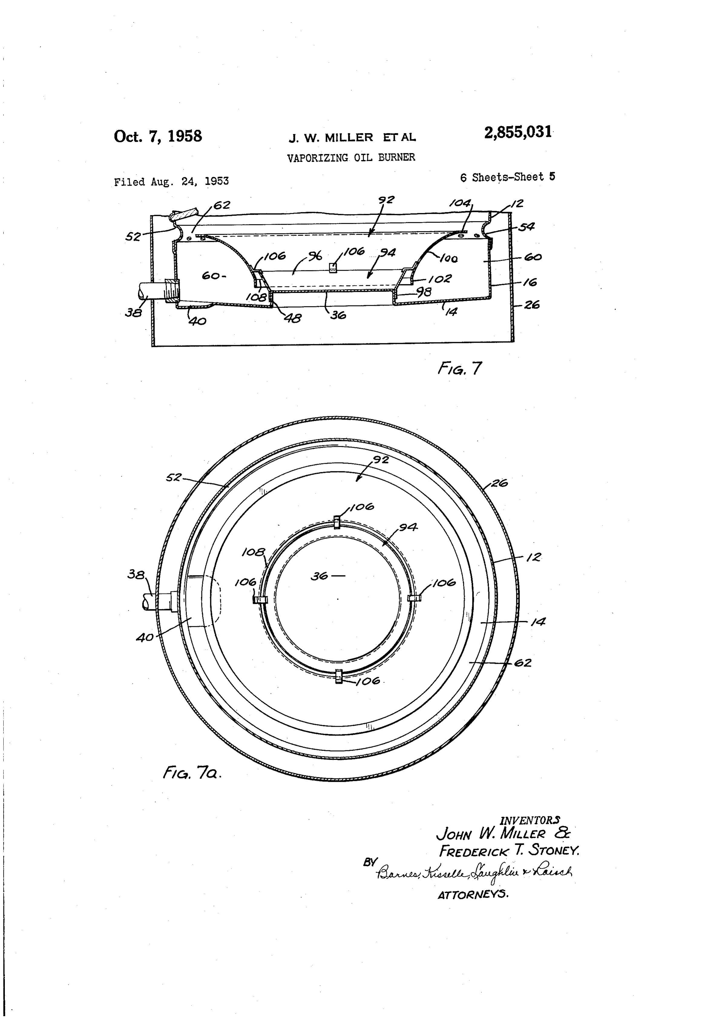
vaporization and an intimate mixing of the oil with air The side wall 2 of the burner pot is provided adja immediately after vaporization and at a relatively low 45 cent its lower end with an inwardly projecting annular temperature. bead 52. A series of primary air inlet openings 54 are Referring to the drawings wherein several embodi formed in bead 52. Openings 54 are arranged around ments of the invention are illustrated: the lower side of bead 52 with the central axes of these Fig. 1 is a fragmentary vertical sectional view through openings extending generally toward the wall 44 of baffle a burner of the present invention showing the operation 50 42 so that the air flowing through these openings im at the high fire stage of combustion. pinges in the form of air jets against, and is deflected Fig. 2 is a fragmentary perspective view of the lower downwardly by, the under side of wall 44. end of the burner pot showing the manner in which the in the operation of the instant burner it is essential baffle is arranged therein. that communication be established between the chamber Fig. 3 is a view similar to Fig. 1 and showing the 55 60 and the inside of baffle 42 so that gases can flow from operation of the burner at the low fire stage of combus within the conical baffle into the mixing chamber 60 ad tion. jacent the lower end of the baffle. This communication Fig. 4 is a horizontal sectional view taken along the between the area within the conical baffle 42 and the line 4-4 of Fig. 1. mixing chamber 60 can be established in several ways. Fig. 5 is a generally sectional view of a modified form 60 By way of example, referring to Figs. 1 to 5, baffle 42 is of burner construction of this invention. provided adjacent its lower end with a series of rectangu Figs. 6 and 7 show modified forms of baffle construc lar slots 56. Slots 56 are arranged as an annular series tion of this invention. spaced slightly above the central raised portion 36 of the Figs. 6a and 7a are top plan elevations of the conical bottom wall of the burner. Slots 56 preferably are baffle arrangements shown respectively in Figs. 6 and 7. 65 formed in the conical wall of the baffle, as shown in Figs. Fig. 8 is an enlarged showing of a portion of the ver 10 and 11, by shearing out the bottom edge only, thus tical sectional view of the burner shown in Fig. 3 to forming a closed end louver 58. Slots 56 can also be more clearly illustrate the flow of air and oil vapors. formed (Figs. 1-5) by shearing the slots along their Fig. 9 is a fragmentary vertical section showing a modi lower and side edges and bending the metal outwardly fied form of baffle arrangement. 70 about the upper edges of these slots and thereby provide Fig. 10 is a fragmentary detail sectional showing of the a generally vertically disposed flange or louver 58 de conical baffle with a modified form of slot, and pending from the upper edge of each slot and shielding
Page 8
the openings 56 from the air entering through inlets 54. the outer face of the baffle sweeps across the openings Baffle 42 cooperates with bottom wall 14 and side walls 56, thus establishing what can be considered a venturi 16 and 48 to define at the base of the burner pot an action which draws the gases from within the conical annular fuel vaporizing. and mixing...chamber 60 having baffle 42 through the slots 56 into the mixing chamber a peripheral opening at its upper end in the form of an 60. The louvers or depending flanges 58 deflect the annular gap 62. defined by the outer edge of. horizontal stream of air or air-oil vapor mixture flowing along flange 50 and the inner face of bead 52. the outside of the baffle, downwardly toward bottom 14 In the operation of the burner, oil flows into the whereupon the flow is radially...outwardly to wall 16 and burner pot through the inlet 38, and spreads out as a then upwardly. The jets of air entering the chamber thin layer over the bottom wall 14. The burner will Ot 60 through inlets: 54 preferably strike. the outer side of i-operate on either natural draft or with mechanical or the baffle 42 above the slots: 56. However, the axes of forced draft. Combustion chamber 26, 28 will be con the inlet opening 54 can be tilted and positioned relative ..nected to a chimney flue in a conventional manner. Air to the outer face of baffle 42 so that the jets or stream of air is directed parallel to, and along the outside of, flows into the lower end of the burner through the primary 5 the baffle 42. One of the principal features is that the sair inlet openings 54 and this air, impinges in the form of air stream should sweep down along the outside of the jets or fingers against the: under side of the inclined wall 44 of baffle .42. Wall 44 deflects this air downwardly baffle 42 and be deflected away from the baffle by the towards the bottom wall 14 and the air then flows in a louvers or baffles 58 to thereby insure a good venturi radially outward direction toward wall 16 over the sur action which draws some of the gases from within the face of oil vaporizing on wall 14. The air thus mixes 20 baffle 42 through the rectangular openings' 56 for recir with the vaporized oil and the mixture flows upwardly culation through and out of the mixing chamber 60. In adjacent the bottom side wall 16 through the annular actual practice it has been found practical, by way of gap or restriction 62 and then upwardly through the example, to tilt the axes of the lower row of primary air burner where it is mixed with further air and then holes 54 in the burner side wall at an angle of approxi burned. Observation of this burner in operation has dis 25 mately 20 to the horizontal. The streams or jets of closed that in general during operation above minimum air that enter the lower row of holes 54 intermix with the fire a portion of the gases in the space 64 directly above vapor arising from the lower wall 14 of the mixing cham ber and these streams of air, deflected downwardly and r; and within-baffle 42 recirculates, that is, flows downwardly - circulating from within conical baffle through slots 56 into chamber across the bottom 14 over the oil film toward -60 where it mixes with the fuel-air mixture initially form 30 the outer periphery of the burner, pick up additional oil ing therein. The flanges or louvers 58 which depend vapor and this air-oil vapor mixture then flows upwardly from the upper-edges of the rectangular slots 56 aid this along the upper wall 16 and passes outwardly through the -circulation of air and oil vapor mixture and also prevent - gap 62 between the pencils of air entering the lower row -escape of the air-oil mixture from chamber 60 upwardly of holes 52.
through slots 56. Baffle 42 thus insures an intimate mix 35 Slots 56, together with the depending flanges 58, or the sing of the oil vapors with air. The baffle 42, also shields equivalent thereof, are necessary to produce efficient “the air-oil-mixture in chamber 60 from the radiant heat combustion with a clean fire. The provision of openings, of the flame in the burner and thus promotes vaporization | Such as the slots 56, substantially improve the operation of the burner. The gases which flow downwardly and of the oil at a relatively low temperature.
In an effort to illustrate more clearly the pattern of 40 outwardly through: the slots. 56 into the vaporizing and the flame, airflow and the flow of air-oil vapor mixture, dead,mixing chamber 60 prevent the formation of pockets of arrows have been incorporated in Figs. 1 and 3 to gen motionless vapors, lower the density of the oil 'erally 'depict this pattern. The arrows 66, formed with vapor fog by reason of dilution and help sweep the air continuous solid lines, represent oil vapor; the arrows oil vapor mixture out of chamber 60 and into the main s'68, formed with short broken lines, represent the flow 45. part of the burner through the annular gap 62. Further of air; and the arrows 70, which are formed by broken the more, the heated gases which flow'downwardly, through lines of different lengths, represent the flow of air-oil ...helps slots 56 supply additional heat to chamber 60 which vapor mixture. promote oil vaporization. In addition, at low fire i:Fig. 1 it will be observed, shows the high fire stage of operation any air in the mixture of gases flowing into the combustion while Fig. 3 shows the same burner at a low mixing chamber through the slots 56, provides additional $fire stage of combustion, intermediate pilot and high 50 primary air for mixing with the oil vapors in chamber fire. In the high fire stage of combustion, shown in 60. It will be appreciated that unless means, such as Fig. 1, the oil flow through inlet 38 is substantially the depending flanges 58, are provided for discouraging -greater than the oil flow during low fire operation. Thus, the movement of air outwardly of the mixing chamber zithe-air-oil vapor mixture flowing from the mixing cham 55. from through openings 56, the improved operation resulting ber 60 in Fig. 1 is richer than the air-oil vapor mixture ...not betheobtained.
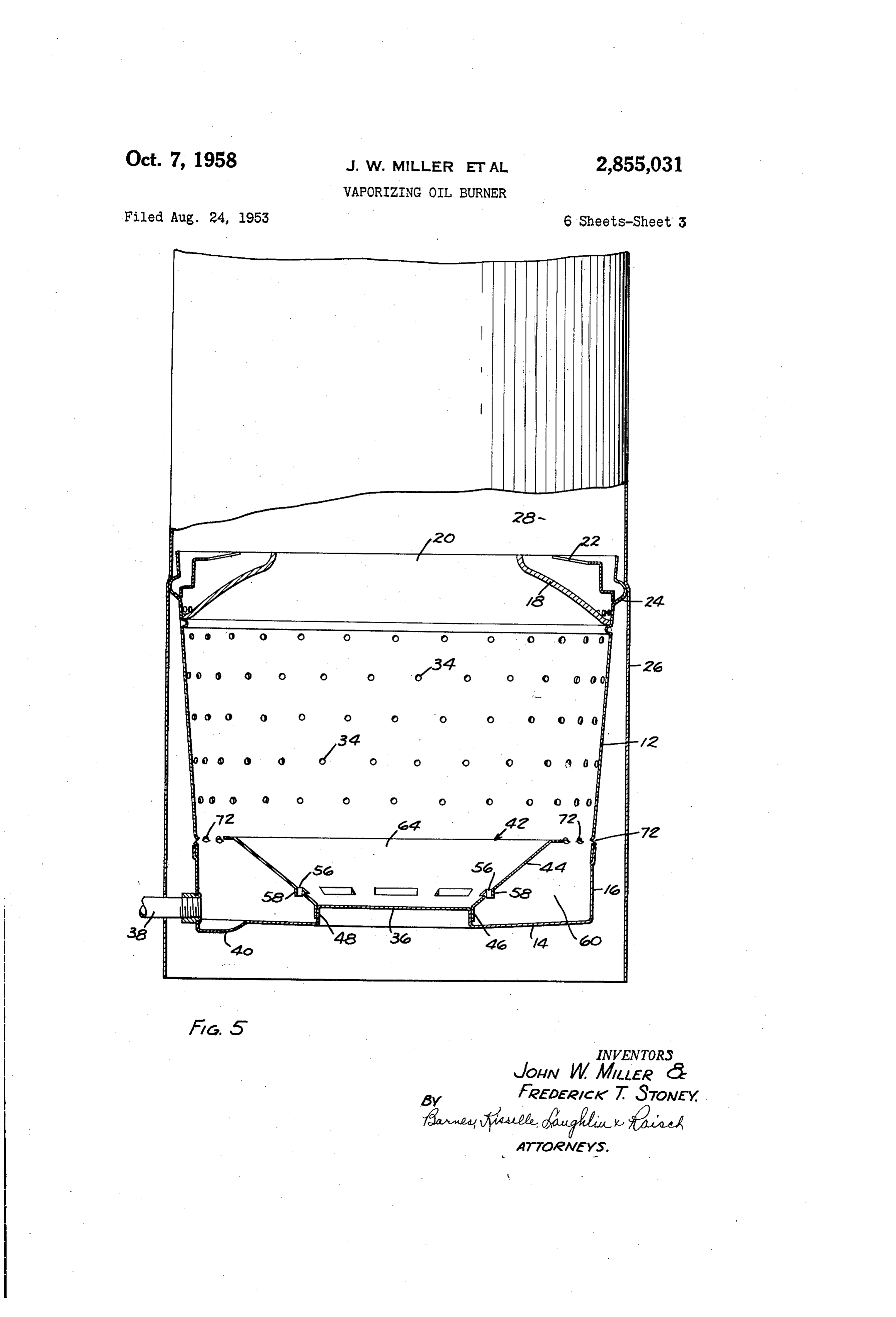
provision of baffle 42, with the slots 56 would ::flowing out of chamber 60 in Fig. 3. The rich mixture is mixed with the streams of air enterng the burner The provision of the central raised portion 36 with its s.through the lar inlet openings 34 above and below baffle cylindrical side wall 48 is desirable from a structural 30 and combustion occurs principally at the upper end, or assembly standpoint also. It, enables the: baffle 42 i and: above the outlet 20, of the burner in combustion 60 to be telescoped over central portion 36 and it eliminates a chamber. 28. At low. fire operation, the air flowing into the necessity for prividing an oil-tight joint between ...the burner through the air inlet openings 34 below baffle baffle 42 and the bottom wall 14 of the burner, such as 30 dilutes the air-oil vapor mixture sufficiently to form wise would be required, if: the baffle were welded or other a combustible. mixture generally in the region of baffle 65 burner. Secured directly to the flat bottom wall:14 of the and combustion therefore occurs principally within The burner arrangement shown in Fig. 5 is generally the burner at, above, or below the central opening 32 of :-baffle:30 and below, outlet 20. The construction shown the same as that illustrated in Figs. 1 to 4 with the excep in Figs. 1. and 3 is the same and the only difference be tion, however, of a modified form of primary air inlet tween the showings of these figures is in the operation opening. In the arrangement shown in Fig. 5, these open , of the burner. 70 ings, designated 72, are formed by perforating the side - During both high and low fire operation of the burner Wall 12 of the burner such that the metal around the upper the air entering the lower row of primary air inlet open half portion of the opening is bent inwardly and the metal ings. 54 flows into the burner in the form of jets. These around the lower half portion of the openings is bent jets of primary air, are directed against the outer or outwardly. In this manner, the axes of the openings are under face...of the baffle. 42.so that the air. flowing down 75 inclined downwardly in-antinward direction so that the
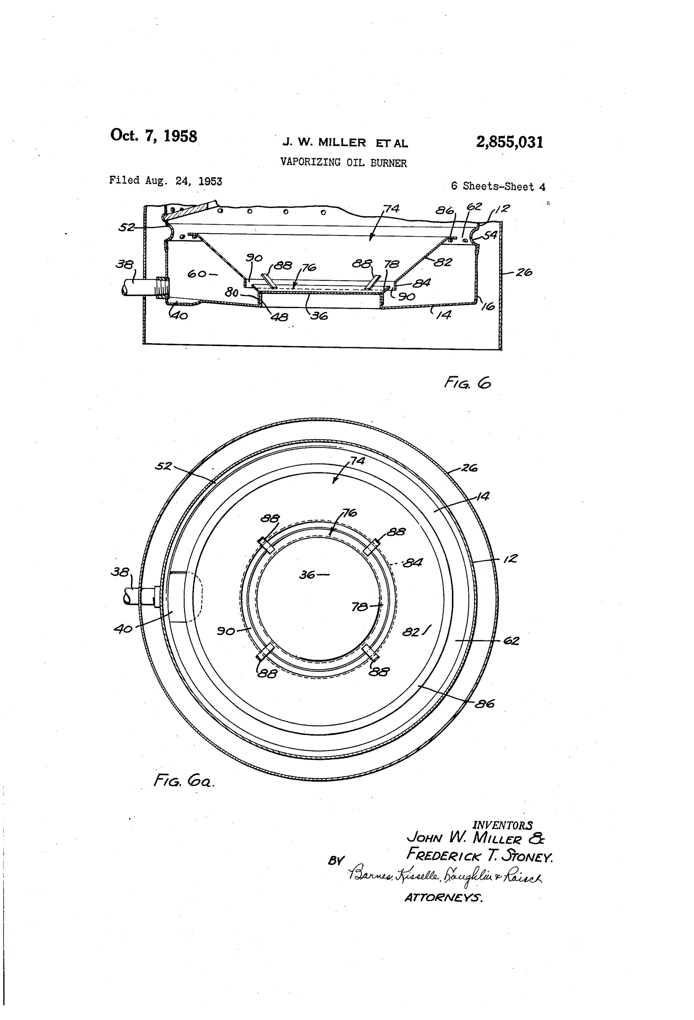
Page 9
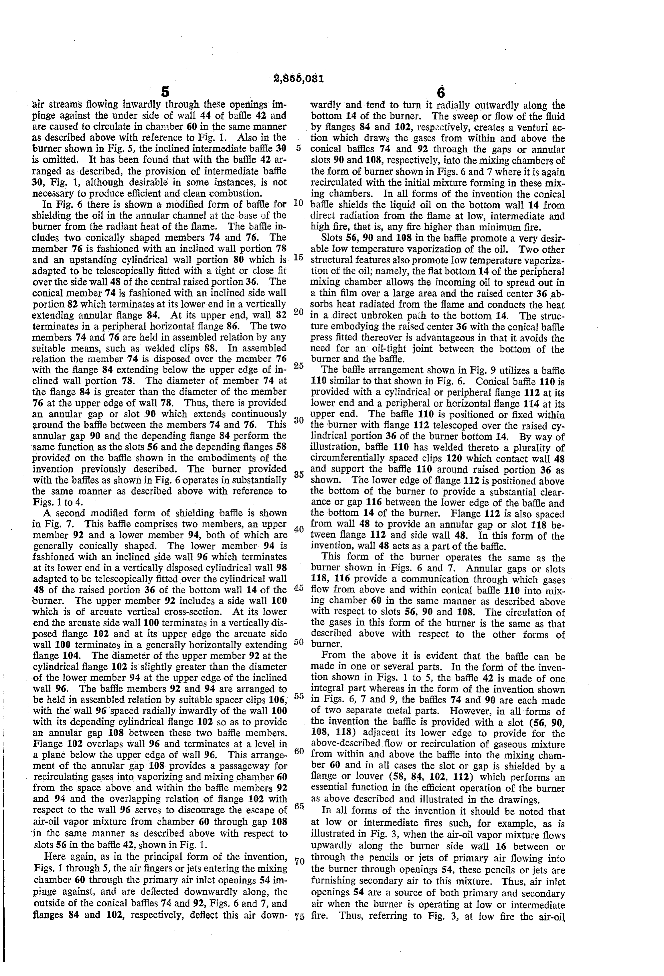
air streams flowing inwardly through these openings im wardly and tend to turn it radially outwardly along the pinge against the under side of wall 44 of baffle 42 and bottom 14 of the burner. The sweep or flow of the fluid are caused to circulate in chanaber 60 in the same manner by flanges 84 and 102, respectively, creates a venturi ac as described above with reference to Fig. 1. Also in the tion which draws the gases from within and above the burner shown in Fig. 5, the inclined intermediate baffle 30 conical baffles 74 and 92 through the gaps or annular is omitted. It has been found that with the baffle 42 ar slots 90 and 108, respectively, into the mixing chambers of ranged as described, the provision of intermediate baffle the form of burner shown in Figs. 6 and 7 where it is again 30, Fig. 1, although desirable in some instances, is not recirculated with the initial mixture forming in these mix necessary to produce efficient and clean combustion. ing chambers. In all forms of the invention the conical In Fig. 6 there is shown a modified form of baffle for O baffle shields the liquid oil on the bottom wall 14 from shielding the oil in the annular channel at the base of the direct radiation from the flame at low, intermediate and burner from the radiant heat of the flame. The baffle in high fire, that is, any fire higher than minimum fire. cludes two conically shaped members 74 and 76. The Slots 56, 90 and 108 in the baffle promote a very desir member 76 is fashioned with an inclined wall portion 78 able low temperature vaporization of the oil. Two other and an upstanding cylindrical wall portion 80 which is 5 structural features also promote low temperature vaporiza adapted to be telescopically fitted with a tight or close fit tion of the oil; namely, the flat bottom 14 of the peripheral over the side wall 48 of the central raised portion 36. The mixing chamber allows the incoming oil to spread out in conical member 74 is fashioned with an inclined side wall a thin film over a large area and the raised center 36 ab portion 82 which terminates at its lower end in a vertically 20 sorbs heat radiated from the flame and conducts the heat extending annular flange 84. At its upper end, wall 82 in a direct unbroken path to the bottom 14. The struc terminates in a peripheral horizontal flange 86. The two ture embodying the raised center 36 with the conical baffle members 74 and 76 are held in assembled relation by any press fitted thereover is advantageous in that it avoids the suitable means, such as welded clips 88. In assembled need for an oil-tight joint between the bottom of the relation the member 74 is disposed over the member 76 25 burner and the baffle.
with the flange 84 extending below the upper edge of in The baffle arrangement shown in Fig. 9 utilizes a baffie clined wall portion 78. The diameter of member 74 at 110 similar to that shown in Fig. 6. Conical bafile 110 is the flange 84 is greater than the diameter of the member provided with a cylindrical or peripheral flange 112 at its 76 at the upper edge of wall 78. Thus, there is provided lower end and a peripheral or horizontal flange 114 at its an annular gap or slot 90 which extends continuously 30 upper end. The baffle 110 is positioned or fixed within around the baffle between the members 74 and 76. This the burner with flange 112 telescoped over the raised cy annular gap 90 and the depending flange 84 perform the lindrical portion 36 of the burner bottom 14. By way of same function as the slots 56 and the depending flanges 58 illustration, baffle 110 has welded thereto a plurality of provided on the baffle shown in the embodiments of the circumferentially spaced clips 120 which contact wall 48 invention previously described. The burner provided 35 and support the baffle 110 around raised portion 36 as with the baffles as shown in Fig. 6 operates in substantially shown. The lower edge of flange 112 is positioned above the same manner as described above with reference to the bottom of the burner to provide a substantial clear Figs. 1 to 4. ance or gap 116 between the lower edge of the baffle and A second modified form of shielding baffle is shown the bottom 14 of the burner. Flange 112 is also spaced in Fig. 7. This baffle comprises two members, an upper 40 from wall 48 to provide an annular gap or slot 118 be member 92 and a lower member 94, both of which are tween flange 112 and side wall 48. In this form of the generally conically shaped. The lower member 94 is invention, wall 48 acts as a part of the baffle. fashioned with an inclined side wall 96 which terminates This form of the burner operates the same as the at its lower end in a vertically disposed cylindrical wall 98 burner shown in Figs. 6 and 7. Annular gaps or slots adapted to be telescopically fitted over the cylindrical wall 118, 116 provide a communication through which gases 48 of the raised portion 36 of the bottom wall 14 of the flow from above and within conical baffle 110 into mix burner. The upper member 92 includes a side wall 100 ing chamber 60 in the same manner as described above which is of arcuate vertical cross-section. At its lower with respect to slots 56, 90 and 108. The circulation of end the arcuate side wall 100 terminates in a vertically dis the gases in this form of the burner is the same as that posed flange 102 and at its upper edge the arcuate side 50 described above with respect to the other forms of wall 100 terminates in a generally horizontally extending burner.
flange 104. The diameter of the upper member 92 at the From the above it is evident that the baffle can be cylindrical flange 102 is slightly greater than the diameter made in one or several parts. In the form of the inven of the lower member 94 at the upper edge of the inclined tion shown in Figs. 1 to 5, the baffle 42 is made of one wall 96. The baffle members 92 and 94 are arranged to integral part whereas in the form of the invention shown be held in assembled relation by suitable spacer clips 106, in Figs. 6, 7 and 9, the baffles 74 and 90 are each made with the wall 96 spaced radially inwardly of the wall 100 of two separate metal parts. However, in all forms of with its depending cylindrical flange 102 so as to provide the invention the baffle is provided with a slot (56, 90, an annular gap 108 between these two baffle members. 108, 118) adjacent its lower edge to provide for the Flange 102 overlaps wall 96 and terminates at a level in 60 above-described flow or recirculation of gaseous mixture a plane below the upper edge of wall 96. This arrange from within and above the baffle into the mixing cham ment of the annular gap 108 provides a passageway for ber 60 and in all cases the slot or gap is shielded by a recirculating gases into vaporizing and mixing chamber 60 flange or louver (58, 84, 102, 112) which performs an from the space above and within the baffle members 92 essential function in the efficient operation of the burner and 94 and the overlapping relation of flange 102 with 65 as above described and illustrated in the drawings. respect to the wall 96 serves to discourage the escape of In all forms of the invention it should be noted that air-oil vapor mixture from chamber 60 through gap 108 at low or intermediate fires such, for example, as is in the same manner as described above with respect to illustrated in Fig. 3, when the air-oil vapor mixture flows slots 56 in the baffle 42, shown in Fig. 1. upwardly along the burner side wall 16 between or Here again, as in the principal form of the invention, 70 through the pencils or jets of primary air flowing into Figs. 1 through 5, the air fingers or jets entering the mixing the burner through openings 54, these pencils or jets are chamber 60 through the primary air inlet openings 54 in furnishing secondary air to this mixture. Thus, air inlet pinge against, and are deflected downwardly along, the openings 54 are a source of both primary and secondary outside of the conical baffles 74 and 92, Figs. 6 and 7, and air when the burner is operating at low or intermediate flanges 84 and 102, respectively, deflect this air down 75 fire. Thus, referring to Fig. 3, at low fire the air-oil
Page 10
vapor' mixture flowing through 'circumferential gap. 62 7... Combustion apparatus of the vaporizing type.com between the upper edge of baffle 64 and wall 16 is a com 'prising an open top-burner pot having a bottom wall; and -bustible mixtures which has been supplied with secondary a side wall, means for directing oil-ontos said bottom air-in the manner above: described.
We claim:
'wall, a baffle in said burner potabove said bottom wall, said baffle being inclined: radially.inwardly; and down
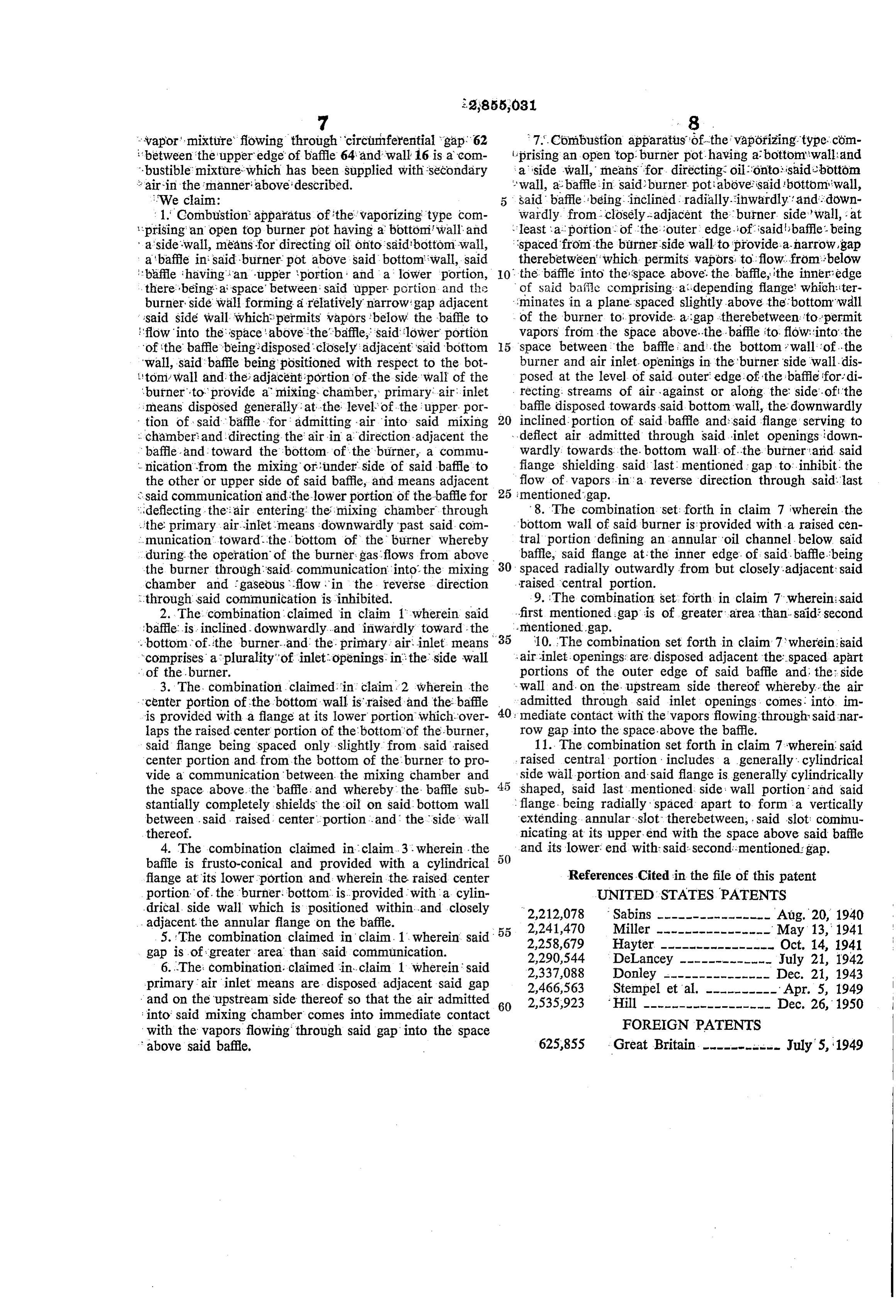
: 1. Combustion apparatus of the vaporizing type com wardly from closely-adjacent the burner side wall, at prising an open top burner pot having a bottom wall and least a portion of the outer edge of said baffle. being a 'side-wall, means for directing oil onto said bottom wall, 'spaced from the burner side wall to provide-a-narrow gap abaffle in said burner pot above said bottom wall, said therebetween which permits vapors to flow. from below it baffle havingian upper portion and a lower portion, 10. the baffle into the space above. the baffle, the inner edge there being a space between said upper portion and the of said ba?ile comprising aidepending flange' which:iter burner sidewall forming a relatively narrow gap adjacent ::minates in a plane spaced slightly above the bottom"wall said side wall which permits vapors below the baffle to of the burner to provide. a gap therebetween to permit 'flow into the space above the baffle, said lower portion vapors from the space above...the baffle to flow into the of the baffle being disposed closely adjacent said bottom 5 space between the baffle, and, the bottom wall of...the wall, said baffle being positioned with respect to the bot burner and air inlet openings in the burner side wall dis 1 tom wall and the adjacent portion of the side wall of the posed at the level of said outer edge of the baffle for: di burner-to-provide a mixing chamber, primary air inlet recting streams of air against or along the side. of the : means disposed generally at the level of the upper por baffle disposed towards said bottom wall, the downwardly tion of said baffle for admitting air into said mixing 20 inclined portion of said baffle and: said flange serving to : chamberi and directing the air in a direction adjacent the deflect air admitted through said inlet openings down baffle and toward the bottom of the burner, a commu wardly towards the...bottom wall of...the burner and said 'nication from the mixing or under side of said baffle to flange shielding said last mentioned gap to inhibit the the other or upper side of said baffle, and means adjacent flow of vapors in a reverse direction through said.last & said communication and the lower portion of the baffle for 25 : mentioned gap.
: deflecting the: air entering the mixing chamber through 8. The combination set: forth in claim 7 wherein the ...the primary air. inlet means downwardly past said com bottom wall of said burner is provided with a raised cen . . munication, toward. the bottom of the burner whereby tral portion defining an annular oil channel below said during the operation of the burner, gas flows from above baffle, said flange at the inner edge. of said baffle-being the burner through said communication into the mixing 30 spaced radially outwardly from but closely adjacent said raised central portion.
chamber and gaseous flow in the reverse direction through said communication is inhibited. 9. The combination set forth in claim 7 wherein: said 2. The combination claimed in claim 1 wherein said first mentioned gap is of greater area than said second ibaffle is inclined-downwardly...and inwardly toward the -mentioned gap.
- bottom of the burner...and the primary: air inlet means 35 air10. The combination set forth in claim 7 wherein: said inlet openings: are disposed adjacent the spaced apart "comprises a plurality of inlet openings in the side wall ... of the burner. portions of the outer edge of said baffle and the: side 3. The combination claimed in claim 2 wherein the wall and on the upstream side thereof whereby the air center portion of the bottom wall is raised and the baffle 40 admitted through said inlet openings comes: into im is provided with a flange at its lower portion which over ! mediate contact with the vapors flowing through said nar laps the raised center portion of the bottom of the burner, row gap into the space. above the baffle. said flange being spaced only slightly from said raised 11. The combination set forth in claim 7 wherein said center portion and from the bottom of the burner to pro raised central portion includes a generally cylindrical vide a communication between the mixing chamber and side wall portion and said flange is generally cylindrically the space above, the baffle, and whereby the baffle sub shaped, said last mentioned side ; wall portion and said stantially completely shields the oil on said bottom wall flange being radially spaced apart to form a vertically between . said, raised center, portion, and the side wall extending annular slot therebetween, said slot commu thereof. nicating at its upper end with the space above said baffle 4. The combination claimed in claim. 3 wherein the and its lower end with said second-mentioned gap. baffle is frusto-conical and provided with a cylindrical flange at its lower portion and wherein the raised center References Cited in the file of this patent portion of the burner bottom. is... provided with a cylin UNITED STATES PATENTS drical side wall which is positioned within...and closely 2,212,078 Sabins ---------------- Aug. 20, 1940 ... adjacent the annular flange on the baffle. 2,241,470 Miller ---------------- May 13, 1941 5. The combination claimed in claim. 1, wherein said 2,258,679 Hayter ---------------- Oct. 14, 1941 gap is of greater area than said communication. 2,290,544 DeLancey ------------- July 21, 1942 6. The combination, claimed in claim 1 wherein said 2,337,088 Donley --------------- Dec. 21, 1943 primary air inlet means are disposed adjacent said gap 2,466,563 Stempel et al. ---------- Apr. 5, 1949 and on the upstream side thereof so that the air admitted 2,535,923 Hill ------------------ Dec. 26, 1950 into said mixing chamber comes into immediate contact 60 with the vapors flowing through said gap into the space FOREIGN PATENTS above said baffle. 625,855 Great Britain ----------- July 5, 1949
Provenance
- Collection
- Cited prior art
- Original PDF
- patentimages.storage.googleapis.com →
- Filed
- 1953-08-24
- Pages
- 10
- Method
- pdftotext (the PDF's own text layer) + pdftoppm 300dpi page scans
- Source
- Google Patents bibliographic record
- Granted
- 1958-10-07
- Inventors
- John W Miller; Frederick T Stoney; Motor Wheel Corp
- Transcribed from
- patentimages.storage.googleapis.com →