patent · US2966942
Electrical ignition assembly for liquid fuel burners
3 January 1961
Page 1
Drawing sheet — no readable text.
Page 2
United States Patent Office 2,966,942 Patented Jan. 3, 1961
a spray nozzle 60 which is located at approximately the
mid-point of the support 52. Oil sprayed through the nozzle 60 may pass downwardly through the space be
ELECTRICAL IGNITIONASSEMBLY FOR LIQUID tween the support 52 and tube 53.
FUEL BURNERS 5 The form of the invention illustrated in Figure 2
James L. Breese and Milton D. Huston, Santa Fe, is closely similar to that illustrated in Figure 1 with the N. Mex, assignors, by mesne assignments, to Controls following essential differences. In this form of the in Company of America, Schiller Park, Ill., a corporation vention, the ignition tube or housing terminates at its of Delaware lower end, at a point generally aligned with the spray 10 nozzle 60. The wick 6 is fixed to the lower end of the
Filed Nov. 4, 1955, Ser. No. 544,918 tube 62 and Surrounds the resistance heating element 63. 5 Claims. (C. 158-91) The lower portion of the wick is beneath the heating element. In this form of the invention oil sprayed from the nozzle 66 comes in contact with the metallic wick 61
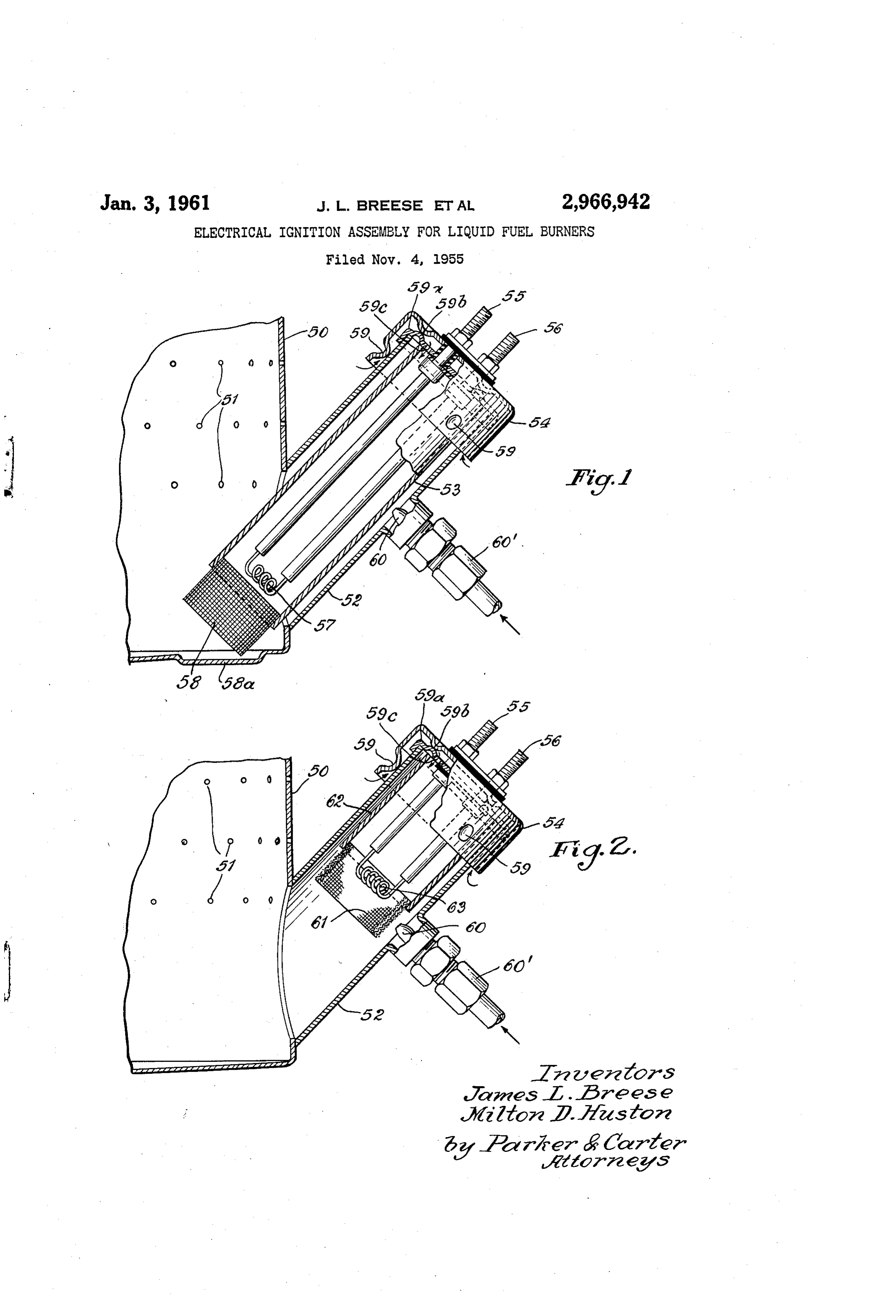
This invention is directed to a new and improved 5 where it is vaporized for combustion.
method and mechanism for igniting the fuel in oil Whereas we have shown and described an operative burners. form of our invention we wish it to be understood that One purpose of the present invention is to provide an there are many modifications of this invention which will improved method of ignition for oil burner pots wherein fall within the scope and spirit of the invention and which the possibility of explosions during the ignition period 20 will be apparent to those skilled in the art. The drawings is materially lessened. and description of the invention should be taken in a dia Another purpose is to provide a heat storage means for grammatic or illustrative sense and the scope of the initially vaporizing a substantial volume of liquid hydro invention should be limited only by the scope of the carbon fuel at the starting stage. hereinafter appended claims.
Yet another purpose is to provide means for bringing 25 The use and operation of our invention is as follows: an oil burner to a high fire condition with a minimum In both forms of the invention we position an ignitor time lag after ignition. tube or housing at an angle to the horizontal. This angle Another purpose is the provision of an improved elec is on the order of 45. This particular disposition of the trical ignition assembly for oil burners wherein a flame ignitor tube facilitates the location of the electrical spreads rapidly and evenly throughout the pot upon 30 leads at a point remote from the pot thus avoiding ignition. damage to the leads due to the heat in the pot. In both Another purpose is the provision of an improved sup forms of the invention, the upper end of the support or porting arrangement of a burner pot and electrical housing for the electrically conductive poles terminates ignition assembly. at a level above the lowermost level of air inlet apertures Other objects will appear from time to time in the 35 in the pot. Thus if any flooding of the pot occurs fuel course of the ensuing specification and claims. will "spill out' through the primary air apertures rather Referring generally now to the drawings: than through the ignition tube. A metallic wick provides Figure 1 is an assembly view in section illustrating the capillary passages for fuel vapors at a point adjacent the improved ignition assembly in its supported position in a resistance heating element and in each form of the in burner pot; and 40 vention these passages surround an opening opposed to Figure 2 is a sectional illustration of a modified form the heating element.
of the invention. En both forms of electrical ignition assembly the hydro Like elements are designated by like characters carbon fuel is initially heated and gasified by electrical en throughout the specification and drawings. ergy. When current is supplied to the resistance heating In Figure the burner pot is designated at 50 and is element the metallic wick will be heated to a sufficient provided with rows or levels of air inlet apertures 51. temperature in relation to the volume of fuel involved, so A Support 52 is joined to the pot wall and is inclined to that when fuel begins to flow, and the wick fills with the wall of the pot as well as the bottom of the pot. An liquid fuel, the stored heat in the wick is itself sufficient to ignitor tube 53 is removably inserted in the support 52. 5) vaporize at least the initial increment of fuel to the wick. The ignitor tube is provided with a shield 54 at its upper This vapor forms about the resistance heating element, end portion. Electrically conductive poles 55 and 56 and also, in the space immediately exterior to the wick. with terminals at their outer ends extend through the In effect, the wick and the adjacent portions of its support shield and terminate adjacent the lower end of the tube. members including the housing and wick support tube A resistance heating element 57 is connected to these two form a heat storage reservoir.
poles at their lower ends. The resistance heating element Means are provided for circulating air through the may be formed of Nichrome wire or other equivalent area of the combustion chamber adjacent the heating ele material. A metallic wick 58 which may be formed of ment. In the forms of the invention illustrated in Figures several superimposed layers of stainless steel screen wire 1 and 2, air external to the burner pot is supplied through may be supported at the lower end of the tube. The 60 the ignition tube to the combustion chamber surrounding wick 58 is positioned closely adjacent the sump 58a in the heating elements. Secondary air is supplied to the the bottom wall of the burner pot. The sump 58a may area surrounding the wick. This flow of air in all cases create some "puddling' of fuel adjacent the wick 58. is insufficient to cool the heating element, when energized, The shield 54 is provided with indentations 59 that below the ignition temperature of the fuel. The flow of make a snug fit with the exterior of the support 53. air is sufficient, however, to initiate primary combustion. An end plate 59a is joined to the tube 53 and overlies the As the vapor due to the stored heat in the wick forms, upper end of tube 53. End plate 59a is spaced from or almost immediately after it begins to form, the vapor the shield 54 as by indentations 59b. Apertures 59c are in the housing within the tube and inside of the wick is formed in the end plate so as to allow primary air for ignited by the resistance and explodes out through the combustion to flow through the Spaces between indenta housing. This initial flame is directed downwardly tions 59, thence through the spaces between indentations 70 toward the bottom of the pot and at a point relatively 59b and down to the area adjacent heating element 57. close to the pot side wall. At the same time, or instan A fuel inlet is designated at 60'. It supplies fuel through taneously thereafter, the vapor in the space exterior to
Page 3
the wick is ignited and the end result is a substantial against loss of heat, a resistance heating element generally combustion of vaporized fuel which is effective to initiate axially aligned with said wick and generally adjacent further vaporization and consequent combustion, the thereto, means for directing a flow of air downwardly ignition of the pot being thus started. Thus the flame toward the heating element, said wick being positioned will spread rapidly and evenly over the surface of oil in the direct path of airflow downwardly within said covering the pot bottom. Support so that a flame produced upon ignition of heated In each form of the invention the ignition tube is vapor in the vicinity of the wick will be projected down simply inserted through the pot wall and may be removed wardly into the pot, and means for delivering fuel to the for inspection and repair if necessary. The ignition tube wick and adjacent supporting portion of the cylindrical may be removed by a simple rectilinear upward and out Support to thereby provide a source of fuel vapor to the ward pull. In both Figures 1 and 2, the upper opening heat storage reservoir.
in the Support is well above the lowermost row of air in 5. A vaporizing liquid fuel burner pot constructed and let apertures and fuel spillage due to flooding of the pot arranged to provide a heat storage reservoir whereby igni will occur through the lowermost row of apertures rather tion of the fuel may occur substantially directly upon than through the support. energization of a resistance heating element, said pot in We claim: cluding, in combination, a generally circumferential side 1. A burner pot and ignition assembly including a wall and bottom, said side wall having a plurality of air vaporizing burner pot for liquid fuels, said pot having admission apertures located therein intermediate the top vertically spaced rows of apertures formed in the side and bottom of the pot, and an opening for an ignition wall thereof for the admission of primary and secondary 20 assembly adjacent the pot bottom, a sleeve in communica air to the interior of the pot, the side wall of the pot hav tion with the opening and having its axis inclined to the ing an opening formed therein, and an insertable and side wall of the pot and the bottom of the pot, and an removable electric ignition assembly aligned with said electrical ignition assembly, at least the bottom portions opening along an axis inclined to the side wall of the pot, of which forms a heat storage reservior insertable and re and to the bottom of the pot, said assembly including a 25 movable in the sleeve in a direction generally parallel to generally cylindrical support positionable with its axis the longitudinal axis of the sleeve, said ignition assembly along said axis, and a generally cylindrical screen wick including a generally cylindrical support, the upper end carried by the end of said support, a resistance heating of said support terminating exteriorly of the said wall, element positioned in the interior of said wick, and a noz and a generally cylindrical wick carried by the lower end zle positioned adjacent said wick and adapted to deliver a 30 of the support, said wick and at least that portion of the stream of fuel against the exterior of said wick. Support adjacent the wick being of a metallic material 2. The structure of claim 1 characterized by and in capable of storing to thereby provide a stand by heat cluding means for delivering air through the interior of storage reservoir, said sleeve surrounding and being spaced said Support and through the interior of said wick in a from the heat storage reservoir so as to protect said heat direction toward the bottom of the burner pot. 35 storage reservoir against loss of heat, a resistance heat 3. The structure of claim 1 wherein said support is ing element generally axially aligned with said wick and positionable generally coaxially with and in the interior generally adjacent thereto, means for directing a flow of of a generally cylindrical tube fixed to the side wall of the air downwardly toward the heating element, said wick be pot and inclined thereto, and said wick and nozzle are 40 ing positioned in the direct path of air flow downwardly located at a position in said tube outwardly and away within said support so that a flame produced upon ignition from the bottom of said burner pot. of heated vapor in the vicinity of the wick will be projected 4. A vaporizing liquid fuel burner pot constructed and downwardly into the pot, and means for delivering fuel to arranged to provide a heat storage reservoir whereby ig the wick and adjacent supporting portion of the cylindrical nition of the fuel may occur substantially directly upon support to thereby provide a source of fuel vapor to the energization of a resistance heating element, said pot in 45 heat storage reservoir.
cluding, in combination, a generally circumferential side wall and bottom, said side wall having a plurality of air References Cited in the file of this patent admission apertures located therein intermediate the top UNITED STATES PATENTS and bottom of the pot, and an opening for an ignition as 50 1903,364 Grant ------------------ Apr. 4, 1933 sembly adjacent the pot bottom, a sleeve in communi 2,229,717 Brace et al. ------------ Jan. 28, 1941 cation with the opening and having its axis inclined to 2,309,319 Johnston -------------- Jan. 26, 1943 the side wall of the pot and the bottom of the pot, and 2,438,823 Resek et al. ------------ Mar. 30, 1948 an electrical ignition assembly forming a heat storage 2,509,399 Resek ---------------- May 30, 1950 reservoir insertable and removable in the sleeve in a direction generally parallel to the longitudinal axis of 55 2,540,594
the sleeve, said ignition assembly including a generally 2,646,111 Long ------------------ Jan. 21, 1953 cylindrical Support, the upper end of said support termi 2,712,352 Manor et al. ------------ July 5, 1955 nating exteriorly of the said wall, and a generally cylin 2,713,388 Todoroff -------------- July 19, 1955 drical wick carried by the lower end of the support, said 60 2,729,282 Lennox ---------------- Jan. 3, 1956 wick and at least that portion of the support adjacent the 2,756,811 Little ------------------ Jan. 31, 1956 wick being of a metallic material capable of storing heat 2,779,398 Brown ---------------- Jan. 29, 1957 to thereby provide a stand by heat storage reservoir, said FOREIGN PATENTS sleeve surrounding and being spaced from the heat storage reservoir so as to protect said heat storage reservoir 477,076 Canada ---------------- Sept. 18, 1951
Provenance
- Collection
- Cited prior art
- Original PDF
- patentimages.storage.googleapis.com →
- Filed
- 1955-11-04
- Pages
- 3
- Method
- pdftotext (the PDF's own text layer) + pdftoppm 300dpi page scans
- Source
- Google Patents bibliographic record
- Granted
- 1961-01-03
- Inventors
- James L Breese; Milton D Huston; Controls Company of America
- Transcribed from
- patentimages.storage.googleapis.com →