patent · US2586493
Burner for liquid fuels
19 February 1952
Page 1
Drawing sheet — no readable text.
Page 2
Drawing sheet — no readable text.
Page 3
Patented Feb. 19, 1952
UNITED STATES2,586,493PATENT OFFICE
BURNER FOR LIQUID FUELS
Michael J. Ward, Detroit, Mich.
Application April 22, 1947, Serial No. 743,143
This invention relates to burners for a liquid spect to the walls of the member 2 said flame fuel adapted for use in a furnace, the object chamber having a central opening 6 at the being to provide a new character of construction and arrangement of parts whereby fuel is fed upper end and the gases in combustion pass therethrough into the body of the furnace.
to a burner and air is supplied directly to the burner and to the burning gases thereabove and by means of an electric circuit, including a tem 8 isSecured a pan to8the bottom which wall? ofcentrally is provided the chamber of its perature controlled switch in the space being upper surface with a flange 9 and centrally of heated, the motor is energized to discharge air the bottom wall of the pan f8 is a vertical recess to the burner. 20, a wall 2 of which extends upwardly above
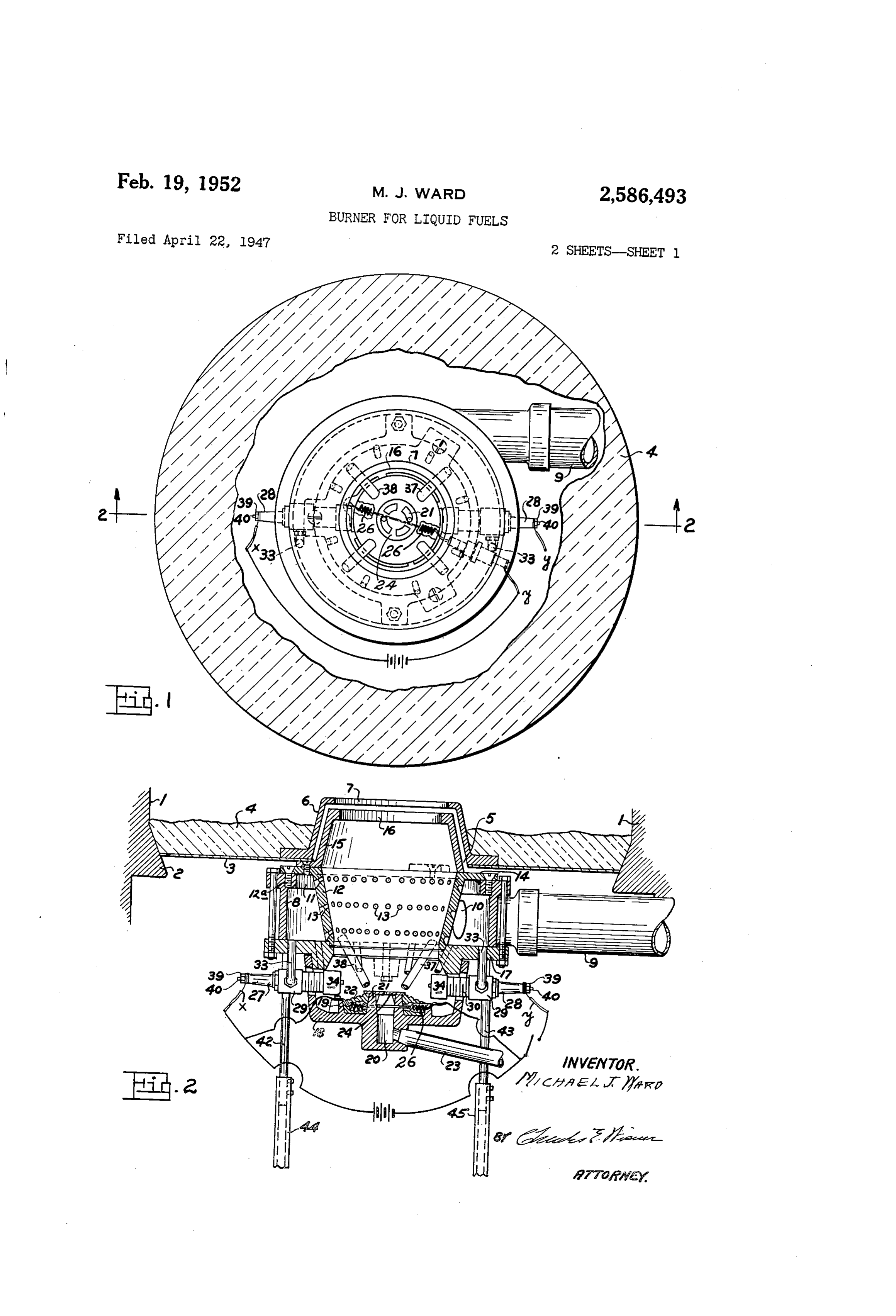
These and other features and objects of the Between the flange f9 and the tubular portion invention are hereinafter more fully described 21 is an element 22 of refractory material having and a burner embodying my invention is shown in the accompanying drawing in which: a ribbed surface and fuel is supplied thereto by Fig. 1 is a plan view of the burner. the conduit 23 opening to the vertical recess 20
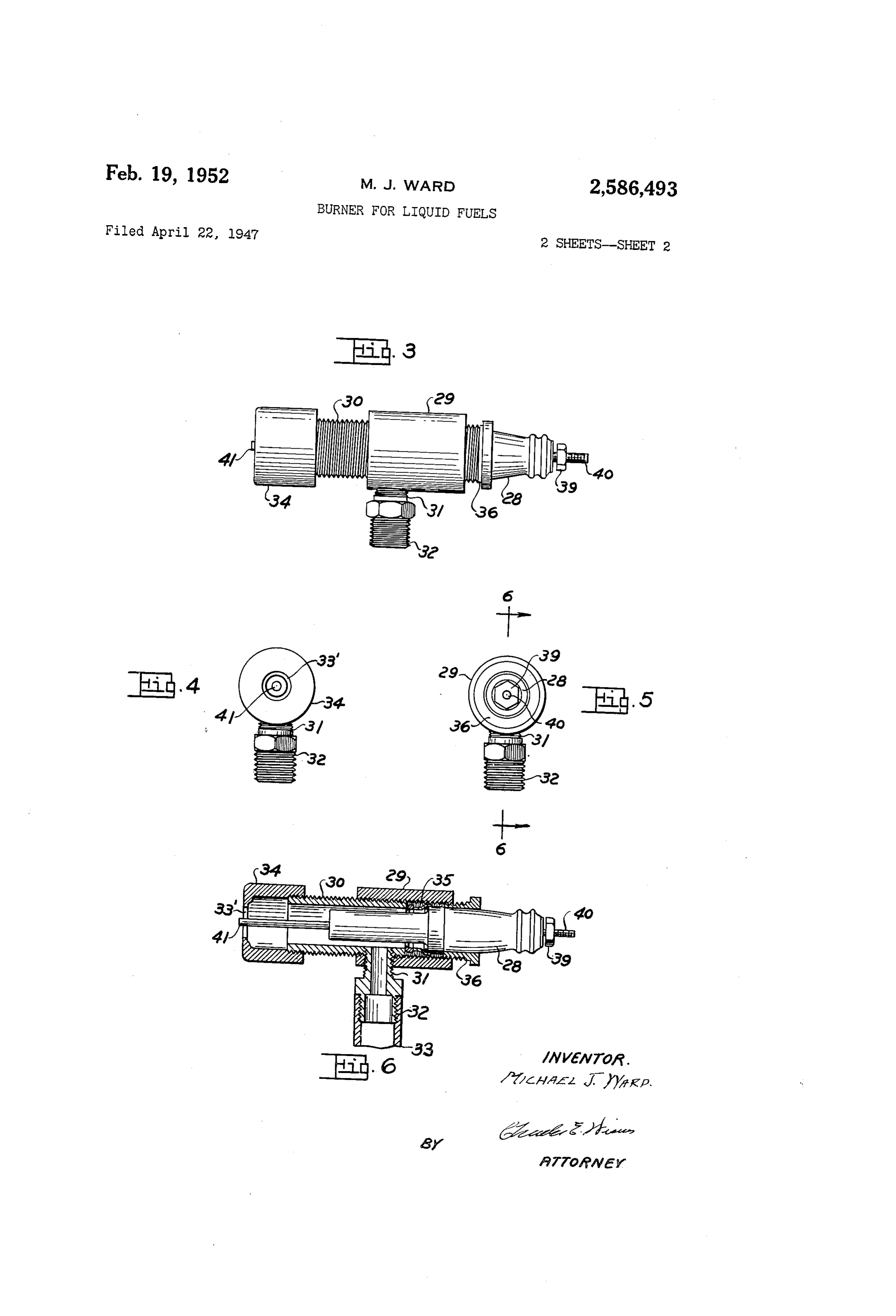
Fig. 2 is a transverse section taken on line the pan 8. At the upper end of the recess 20 2-2 of Fig. 1. is a plate 24 and fuel may flow through an aper Fig. 3 is an elevation of my improved ignition ture of theinrefractory said plateelement and over 22. the ribbed surface device.
Fig. 4 is an end elevation taken from the left 20 The refractory element has embedded therein hand side of Fig. 3. a heating coil or coils 26 connected with the Fig. 5 is an elevation taken from the right hand terminals ac and g of an electric circuit with side of Fig. 3. which the respective ignition plugs 27 and 28 Fig. 6 is a longitudinal section taken on line are to be understood as being connected. The 6-6 of Fig. 5. ignition plugs are of special construction as 25 shown in detail in Figs. 3 to 6 inclusive.
As will be understood more clearly from Fig. 2 As shown more particularly in Fig. 6 the plug the burner is positioned within a furnace the consists of the body 29 internally threaded to walls of which are indicated at and as here receive the end of an externally threaded tubular shown is of circular form and has an inwardly extending flange 2. Supported on this flange is 30 member 30. Each of the members 29 and 30 have aligned apertures in one side to receive the a plate 3 on which is positioned insulating ma terial 4. terminal 3 which is externally threaded as indi The plate 3 has an aperture 5 and if the fur cated at 32 to receive the air supply tube 33 as nace chamber is cylindrical in form the aperture shown in Fig. 6. The air supply tube 9 has an opening 0 to the air space between the member is centrally disposed and on the plate is sup 8 and the member 2 into which space air is ported a hood 6 the side walls of which are in
Wardly tapered and provide an opening 7 in discharged and thus cools the body of the plug. As shown in Fig. 6 there is a sealing element the upper face thereof.
Below the plate 3 is an air chamber 8, here 35 between the end of the tube 30 and the cap shown as being of cylindrical form and an air 40 36 which secures the plug in place. By this arrangement a constant stream of air flows
Supply conduit 9 is provided on one side thereof and air is discharged thereinto through an open aboutoverheating the body of the plug and thus tends to pre ing 0 to the interior of the cylindrical chamber Vent air over the thereof and further discharges burner plate as will be understood 8 which has an opening fl in its upper side. from Fig. 2.
Within the chamber 8 is an air distributor 2 45 Air also discharges over the burner plate having a series of inwardly and upwardly in through the tubes 37 and 38 the upper ends of clined passageways 3 in the side wall.
By this arrangement air discharging through which are open to the air space to which the tubes 33 are also open and, as the air ascends through the conduit 9 passes through the inwardly and the flame chamber 5, additional air is provided upwardly inclined passageways 3 in the dis tributor Wall. The flange f4 of the distributor through
It will the apertures 3 in the air distributor.
be more clearly understood from Fig. 6 2 is secured to the upper face of the chamber 8 by means of Screws 2a. Secured to the upper that the plug 28 may be connected in the elec face of the flange 4 is a flame chamber 5 hav tric circuit by means of a nut 39 on the termi nal 40, the opposite end 4f of which extends ing the walls thereof reversely inclined in re 55 centrally through the aperture 33' in the cap 34.
Page 4
The plug is prevented from becoming overheated chambered element and with their lower ends due to air supply pipes 33 which supply also air extending into the Said pan. for combustion. 2. A liquid fuel burner comprising a cham The burner as a whole is supported by stand bered element having a lower horizontal wall ards 42 and 43 which are vertically adjustable in 5 and being open at its upper end, an open ended air distributor of substantially conical form ex the supporting elements 44 and 45 the lower end tending downwardly thereinto, an Outwardly di of which are supported by the bottom of the rected horizontal flange at the top of Said distrib furnace, not here shown. utor bearing upon the upper end of said cham It is to be understood that there is an elec 0 bered element, the lower wall of the chambered trically operated blower not here shown for Sup element having an aperture to which the lower plying air to the conduit 9 and the blower is end of said distributor is connected, said distrib connected in the circuit with the ignition plugs utor having a series of transverse apertures in and thus, when the thermostat opens the electric its wall, means for supplying air to said cham circuit is opened, the blower ceases to function as is also true of the Spark plugs. When the cir bered element to discharge through said aper cuit is closed by a drop in temperature in the tures to the interior of said distributor, a burner space being heated the Spark plugs are caused pan supported below the lower open end of said to function at the same time. distributor and depending from the lower wall of By this arrangement of parts the temperature said chambered element in communication with of the space being heated is maintained prac its aperture, means by which fuel is discharged tically constant. into said pan, a fuel ignition device having a Having thus briefly described my invention, its chambered body and an open inner end projected through the side wall of said pan, and a conduit utility and mode of operation, what I claim and communicating at One end with the interior of desire to secure by Letters Patent of the United said chambered element with its other end open States is: ing into the interior of said body for delivering l, A liquid fuel burner comprising a cham air therethrough.
bered element having a lower horizontal wall and MICHAEL J. WARD. being open at its upper end, an open ended air distributor of substantially conical form extend 30 REFERENCES CTED ing downwardly thereinto, an outwardly directed The following references are of record in the horizontal flange at the top of said distributor file of this patent:
bearing upon the upper end of said chambered UNITED STATES PATENTS element, the lower wall of the chambered ele Number Name Date ment having an aperture to which the lower end 1,670,819 Morris et al. -------- May 22, 1928 of said distributor is connected, said distributor 1,674,282 Fletcher ---------- June 19, 1928 having a Series of transverse apertures in its 1,677,447 Higgins et al. ------ July 17, 1928 wall, means for supplying air to said chambered 1,711,140 D'Elia et al. -------- Apr. 30, 1929 element to discharge through said apertures to 40 1862,910 Schutz ------------ June 14, 1932 the interior of said distributor, a burner pan Sup 2,175,866 Arnold ------------- Oct. 10, 1939 ported below the lower open end of said distribu 2,194,081 Bock ------------- Mar. 19, 1940 tor and depending from the lower wall of said 2,275,002 Barr --------------- Mar. 3, 1942 chambered element in communication with its aperture, means by which fuel is discharged into 45 2,388,907
said pan, a fuel ignition device, an electrical cir 2,391,585 Miller ------------- Dec. 25, 1945 cuit therefor, and a plurality of conduits con 2,431,456 Bock -------------- Nov. 25, 1947 nected at their upper ends to the interior of said
Provenance
- Collection
- Cited prior art
- Original PDF
- patentimages.storage.googleapis.com →
- Filed
- 1947-04-22
- Pages
- 4
- Method
- pdftotext (the PDF's own text layer) + pdftoppm 300dpi page scans
- Source
- Google Patents bibliographic record
- Granted
- 1952-02-19
- Inventors
- Michael J Ward
- Transcribed from
- patentimages.storage.googleapis.com →