patent · US2769411
Fuel combustion process and apparatus
6 November 1956
Page 1 — bibliographic record
Nov. 6, 1956 T. M. G. SIMMONS 2,769,411
FUEL COMBUSTION PROCESS AND APPARATUS
Filed Nov. 6, 1951 . 2 Sheets-Sheet
INVENTOR.
ORSTEN MAGNUS GORG SMMONS
Corell/30J-3s lau
HS AT TORNEYS.
Page 2
Nov. 6, 1956 T. M. G. SIMMONS 2,769,411
FUEL COMBUSTION PROCESS AND APPARATUS
Filed Nov. 6, 1951 2 Sheets-Sheet 2
NVENTOR.
TORSTEN MAGNUS GEORG SMMONS
0-ri-94-1.4gas -4-aw HIS AT TORNEYS. .
Page 3
United States Patent Office Patented Nov. 6, 1956
from the gas and continually or periodically removed from the system, while the gas thus purified from the said com 2,769,411 ponents is discharged from the separator and can be uti lized for some purpose, for instance heating. Alternative
FUEL COMBUSTION PROCESS AND ly the purified gas can heat the same contrivance as that APPARATUS heated by means of the gases passing through the main Torsten Magnus Georg Simmons, Norrkoping, Swede, exhaust. This method is especially suitable for use when assignor, by mesne assignments, to Rosenblad Corpora burning fuel concentrated in ashes, for instance waste tion, New York, N.Y., a corporation of New York sulphite lye. At the same time the ashes are removed O from the system.
Application November 6, 1951, Serial No. 255,097 3. The gas purified from solid components, preferably 2 Claims. (C. 110-28) in the same way as in the case 2, is returned to the com bustion chamber at a part thereof located at least in the vicinity of the place, at which the fuel was initially intro
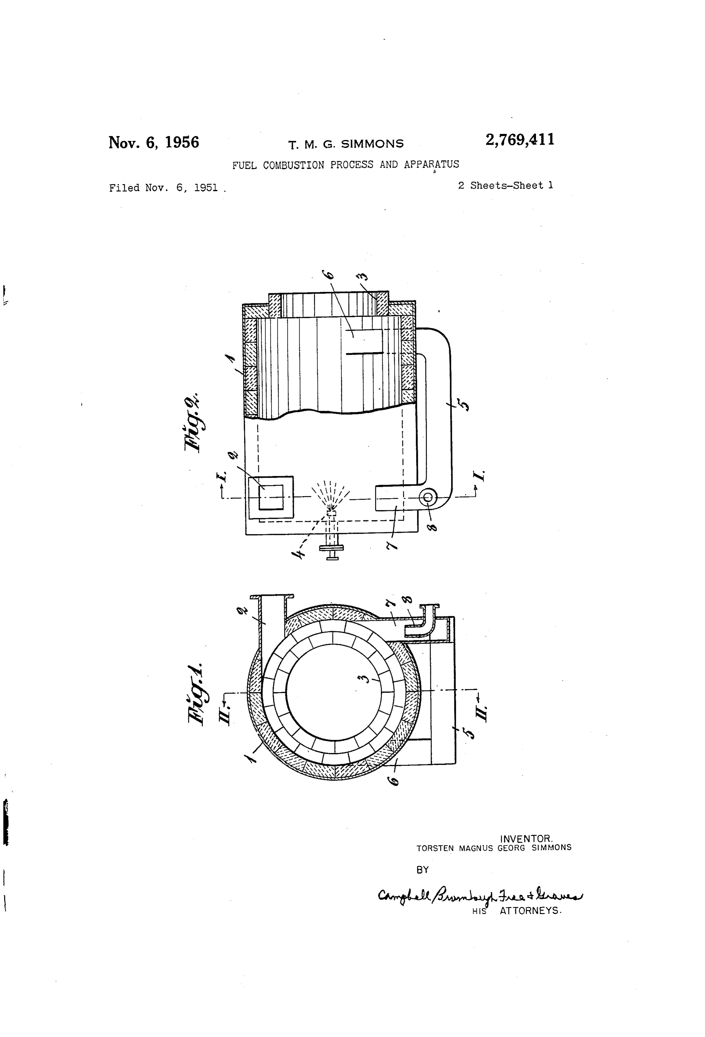
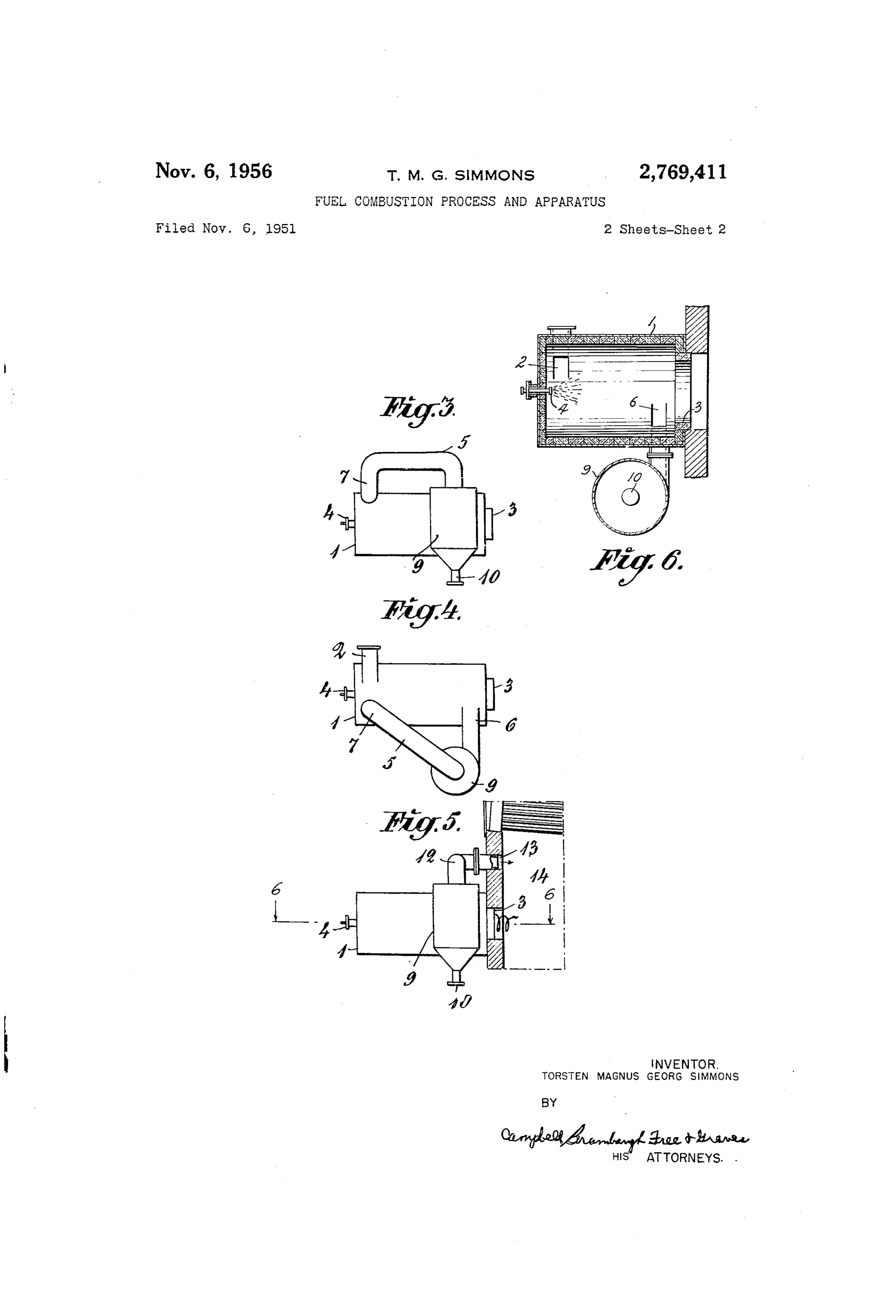
This invention relates to combustion in a combustion 5 duced. This method is particularly suitable to be used at chamber of the so called whirl chamber type having an firing with hydrous fuel rich in ashes, for instance waste approximately circular cross section, and in which air and sulphite lye so as to effect a high temperature in the dry combustion gases containing solid components are caused ing Zone of the combustion chamber at the same time as to stream through the chamber in a helical path along separation of ashes is effected. the interior surface of the chamber in the direction to 20 Some embodiments of the invention are shown diagram wards a main exhaust through which said gases are dis matically in the accompanying drawings, in which charged so as to heat the heating surfaces of a boiler for Fig. 1 is a cross-section of an arrangement according instance. Conditions of this kind arise in the combustion to the invention on the line I-I of Fig. 2. of fuel introduced into the combustion chamber in the Fig. 2 is a side view of the same arrangement on the form of powder or lumps, but can also arise if a hydrous 25 line II-II of Fig. 1, some parts being sectioned. liquid fuel, for instance waste sulphite lye evaporated to Fig. 3 shows a side view of a modified arrangement on contain 50-60% of dry substances, is injected into the a smaller scale, chamber in the form of a spray or drops. The drops will Fig. 4 is a plan view of the same modification, then be ignited only after having dried to powder, where 30 Fig. 5 is a side view of still another modification con upon the combustion process will take place in the same nected to the fire place of a boiler, and way, as if the fuel had been initially introduced into the Fig. 6 is a view in transverse section taken on the line chamber in such a pulverized form, so that the combus 6-6 of Fig. 5.
tion of the dried particles will proceed while they are being Figures 1 and 2 are intended to illustrate the alternative carried on by the whirl of air and gases. As far as possible 35 case 1 aforesaid, while Figures 3 and 4 illustrate case 2 losses of particles of fuel through the main exhaust should and Fig. 5 case 3.
be prevented. Especially when burning fuels having large As will appear from Figures 1 and 2 the approximately contents of ashes it is also important to prevent that large cylindrical combustion chamber 1 is of the whirl chamber quantities of ashes proceed that way and form coatings on type and has one or more inlets 2 for-introducing com the heating surfaces thus necessitating frequent cleaning bustion air tangentially to its interior cylindrical wall of said surfaces. 40 surface, and one or more main exhausts 3 for the dis The main object of the invention is to remove contin charge of combustion gases preferably in axial direction, uously such solid substances from the combustion cham the main exhaust or exhausts having a cross sectional ber, before being discharged through the main exhaust. area, as shown in the drawings, which is restricted in A further object of the invention is to utilize to this 45 relation to the cross sectional area of the adjacent part purpose the characteristic feature of the aforesaid type of the combustion chamber. The fuel which can consist of combustion chamber, namely that owing to the influ of evaporated Sulphite lye but also of a fluid sulphite lye, ence of the centrifugal force the layer of the combustion for instance, is injected into the combustion chamber in gas whirl moving adjacent to the interior wall surface of an atomized state through one or more atomizers 4. A the chamber will be enriched or concentrated in solid duct 5 is arranged to connect a preferably tangential components. 50 outlet 6 from the chamber in the vicinity of the main Still a further object of the invention is to remove or exhaust 3 with an inlet 7 to the chamber also preferably tangential. Viewed in the axial direction of the chamber discharge combustion gases enriched or concentrated in or mixed with solid components from a part of the inte said inlet 7 is situated farther away from the exhaust 3 rior cylindrical wall surface of the chamber at a point in 55 than the outlet 6. A tube 8 for gas, air or steam can open the vicinity of and-viewed in the direction of flow of the into the inlet 7 or at some other point of the duct 5. gas whirl-before the main exhaust. During the operation the combustion air together with A further object of the invention is to treat the gas thus the combustion gases generated will flow on a helical discharged in any of the following alternative ways: path through the chamber from the inlet 2 to the main 1. The gas together with its contents of solid compo exhaust 3. The whirl of gases establishes a certain pres nents is conducted back to a part of the combustion cham 60 sure effect at the outlet 6, and a relative sucking effect ber which-viewed in the flowing direction of the com at the inlet 7, so that the combustion gases enriched in bustion gas through the chamber-is situated before that solid particles will be sucked through the duct 5 from the part from which the gas is discharged. This process is outlet 6 into the chamber at the inlet 7. This sucking particularly suitable to be used in the case when the solid
effect can be intensified by means of a flow of gas, steam, components, to a substantial extent at least, consist of or air, which at a relatively great speed is blown into particles of fuel not completely burnt. In this way I the inlet 7 through the tube 8. The liquid fuel injected gain the advantage that said particles are forced again to in the form of drops or a spray through the nozzle 4 pass through the chamber and then will be subjected to is dried in the chamber 1 so as to form grains or a complete and final combustion. powder under the influence of the heat radiated from the 2. The gas together with its contents of solid compounds 70 walls of the chamber and from the burning particles of is caused to pass through a separator, for instance of the fuel. These particles in the form of grains or powder are cyclone type, in which said solid particles are separated caught by the air-gas whirl, ignited, and burnt in the state
Page 4
3 - 4 of grains or powder. Under the influence of the cen The invention is not restricted to the particular embodi trifugal force the particles are carried in the direction to ments now described which, are to be regarded as being wards the interior cylindrical surface of the chamber and illustrative but not limiting. - the particles which have not been burnt before they reach What I claim is:
said cylindrical surface will be carried on by the air-gas 1. In a combustion process for using fuel which yields stream, and move in helical paths along the cylindrical - Solid components of combustion, the steps of passing the surface towards the main exhaust 3 under continued com fuel and air into one end of a whirl type combustion bustion. At least a considerable part of the particles, chamber having an axial main exhaust at its other end, which have not been completely. burnt at their arrival causing the fuel to ignite and the ignited fuel, air and at the outlet 6, are discharged therethrough and returned O combustion products to flow in a helical path toward the by the combustion gases through the duct 5 to the inlet main exhaust, thereby causing the peripheral layer of 7 so as to be subjected to complete combustion during gas nearest the interior surface of the chamber. to-be their renewed passage through the chamber 1. Prefer come enriched, under the influence of centrifugal force, ably, the inlet 7 opens in or at the part, where the new with solid components, tangentially withdrawing the en fuel just introduced into the chamber 1 is caused to dry 5 riched gases from the periphery of the helical flow path in and/or be ignited. The duct 5 can be built in or en the vicinity of and in advance of the main exhaust, sepa closed into the wall of the chamber 1, if desired, and a rating the solid components from the withdrawn en pump can be arranged instead of the tube 8. riched gases externally of the combustion chamber for According to Figures 3 and 4 the gases concentrated or removal from the combustion process, and passing the enriched in solid components are conducted from the tan 20 remaining combustion gases in the combustions chamber gential outlet 6 to a cyclone 9 or some other separator, through the main exhaust for heating purposes, and pass in which the solid components are separated from the ing the gases from which the solids components have gases, and carried away from the system through a bottom been separated into the same heat consuming contrivance. outlet 10, while the gases purified from said components 2. An arrangement for the combustion of fuel result are returned through the duct 5 to a place in the combus 25 ing in solid components of combustion, comprising in tion chamber nearer to the fuel nozzle 4 than to the combination an elongated combustion chamber of the outlet 6. In that way also the particles carried away whirl type having at least one restricted main exhaust for through the outlet 6 are separated through the cyclone 9. combustion gases at one end, means defining at least one Fig. 5 diagrammatically shows an embodiment accord tangential subsidiary outlet at the interior wall of the ing to which the combustion gases concentrated or en 30 chamber in the vicinity of the restricted main exhaust for riched in solid particles and escaping through the outlet gases enriched in solid fuel components due to centrifugal 6. (not shown) after separation in the cyclone 9 are dis force, means for injecting the fuel and air at the opposite. charged through a tube 12, which preferably opens into end of the chamber to cause gases and solid components an inlet 13 in the same fire place 14 (for instance a boiler) to stream through the chamber in a helical path along as the main exhaust 3 from the chamber 1, so that the 35 the interior wall of the chamber to said subsidiary outlet contents of heat of all combustion gases generated in the and the main exhaust, a separator outside the furnace for chamber will be utilized in said fire place. This is also separating solid components from the gases enriched the case in the embodiments according to Figures 1-4, thereby, a duct connection between the subsidiary outlet though in these cases the gases discharged through the and the separator for conducting the gases enriched with outlet 6 first are returned. However, the tube 12 can 40 solid components to the separator, and a discharge outlet alternatively also be connected to some other contrivance from the separator for said gases from which the solid for the utilization of the heat of the gases. components have been extracted, first means to connect According to an alternative embodiment two or more the discharge outlet of the separator to a heat consuming return ducts 5 can be arranged, for instance if the com contrivance and second means to connect the main ex bustion chamber. is provided with means for the introduc 45 haust of the furnace to the heat consuming contrivance. tion of fuel in its middle part between the ends each of which has a main exhaust. Each duct will then return References Cited in the file of this patent w the gas enriched in solid particles from a place in the vicinity of the end part to a place nearer to the injection UNITED STATES PATENTS . . . means of fuel. If on the other hand the main exhaust is 50 1,427,176 Taylor ---------------- Aug. 29, 1922. arranged at the middle part of the chamber and the intro 1,618,808 Burg ----------------- Feb. 22, 1927. duction of fuel at each end, each of the two return ducts 2,465,464 Meyer ---------------- Mar. 29, 1949. will be arranged to return the gas enriched in solid par ticles from a place in the vicinity of the middle part to a place nearer to the injecting means of fuel at the ends. 55 915,838
FOREIGN PATENTS
Provenance
- Collection
- Cited prior art
- Original PDF
- patentimages.storage.googleapis.com →
- Filed
- 1951-11-06
- Pages
- 4
- Method
- pdftotext (the PDF's own text layer) + pdftoppm 300dpi page scans
- Source
- Google Patents bibliographic record
- Granted
- 1956-11-06
- Inventors
- Simmons Torsten Magnus Georg; Rosenblad Corp
- Transcribed from
- patentimages.storage.googleapis.com →