patent · US2200861
Apparatus of combustion
14 May 1940
Page 1
Drawing sheet — no readable text.
Page 2
Drawing sheet — no readable text.
Page 3
Patented May 14, 1940 2,200,861
UNITED STATES PATENT OFFICE 2,200,861
APPARATUS OF COMBUSTION
John s. Peoples, Chicago, III., assignor of one fourth to Sangston Hettler, Chicago, Ill.
Application October 19, 1935, serial No. 45,730
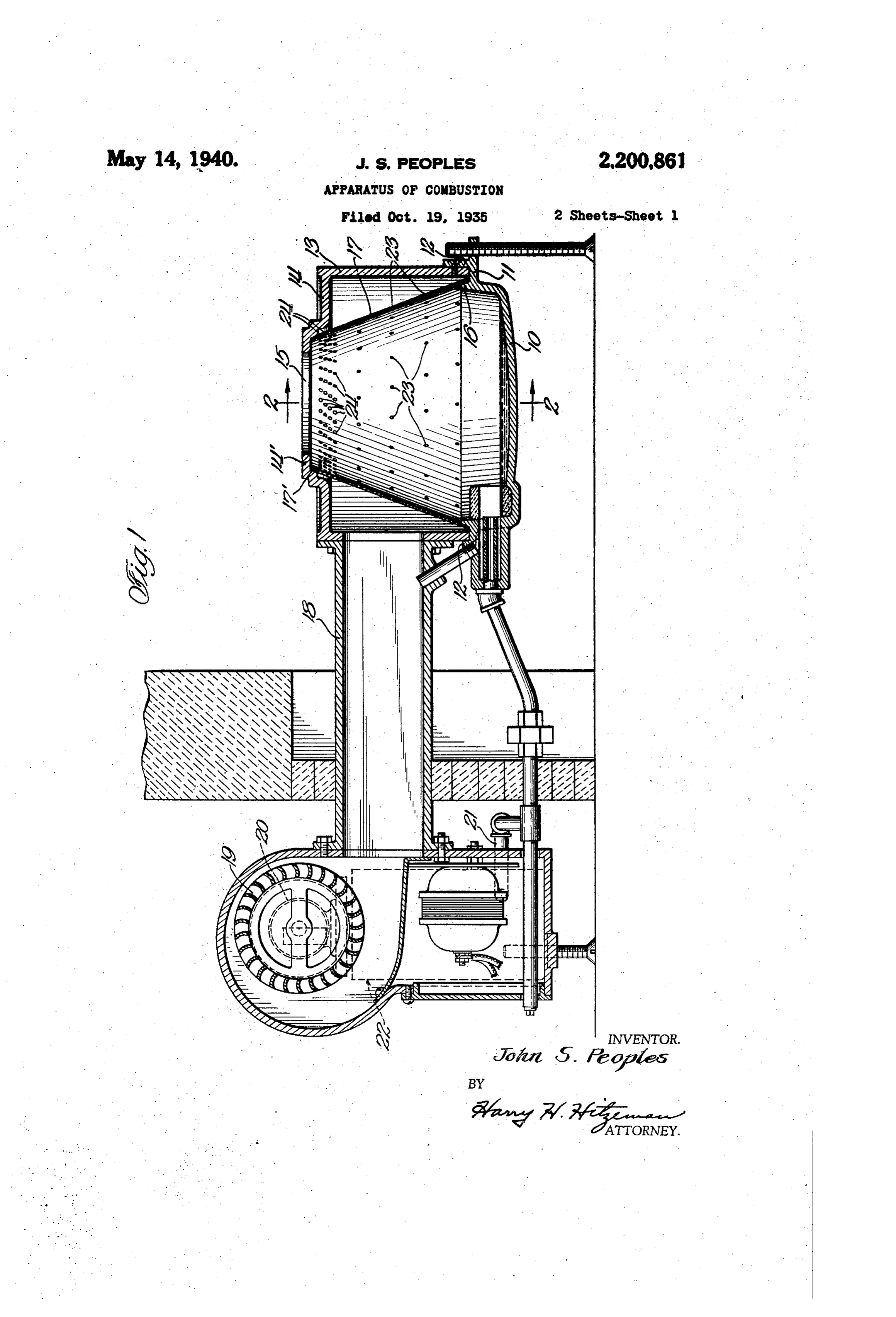
This invention relates to apparatus for Com edge of the cone 7. This cone tapers upward bustion and more particularly to apparatus and and its upper edge seats against a face fl' pro process of combustion of oil. - vided by one of the step formations of the wall. One of the objects of the invention is to pro f4. The wall 4 has an annular portion 4' which vide an improved apparatus for the combustion of oil.
extends inwardly beyond the cone T for a pur pose hereinafter described. The cone? and the
A further object of the invention is to provide housing 3 constitute between them an annular an oil burner. in which forced draft is provided . . chamber for air. . which is supplied through a in such a way that practically all of the ap
O paratus is cooled thereby and protected from the conduit f8 which may be bolted to the housing effects of the heat.
3. This air is supplied by a blower 9, prefer 10 ably of the squirrel cage type, which is driven by
A further object of the invention is to provide suitable means, for example an electric motor 20. an improved oil burner in which air is first The oil is supplied by the pipe 2? to the vessel efficiently carbureted and thereafter the fuel and to from a suitable control of known type illus s the air are Subjected to combustion.
trated diagrammatically and designated by the 5
A further object of the invention is to provide reference numeral 22. This control comprises an an oil burner provided with a reflection surface electrically operated valve together with a float associated with a combustion zone in such a man valve which closes automatically when a prede ner that radiant heat is reflected upon the oil termined maximum level is reached. As a result, for the more efficient vaporization thereof. When the conventional control such as the usual A further object of the invention is to provide household thermostat calls for heat, the first 20 an oil burner in which a pool of oil is maintained valve is opened and oil passes into the dish-like in an open vessel during an operation and which yessel O. until the appropriate depth is attained. Will come to efficient combustion condition in a When the thermostatic control closes the elec 25 minimum of time.
Other objects, advantages and capabilities of trical valve in the control element 22, the oil 2 5 in the vessel O is completely consumed. The the invention will appear from the following de motor 20 is preferably arranged to run con scription of a preferred i embodiment thereof tinuously, although suitable means may be pro taken in conjunction with the accompanying 30 two sheets of drawings, in which: vided to render it intermittent so as to Supply air
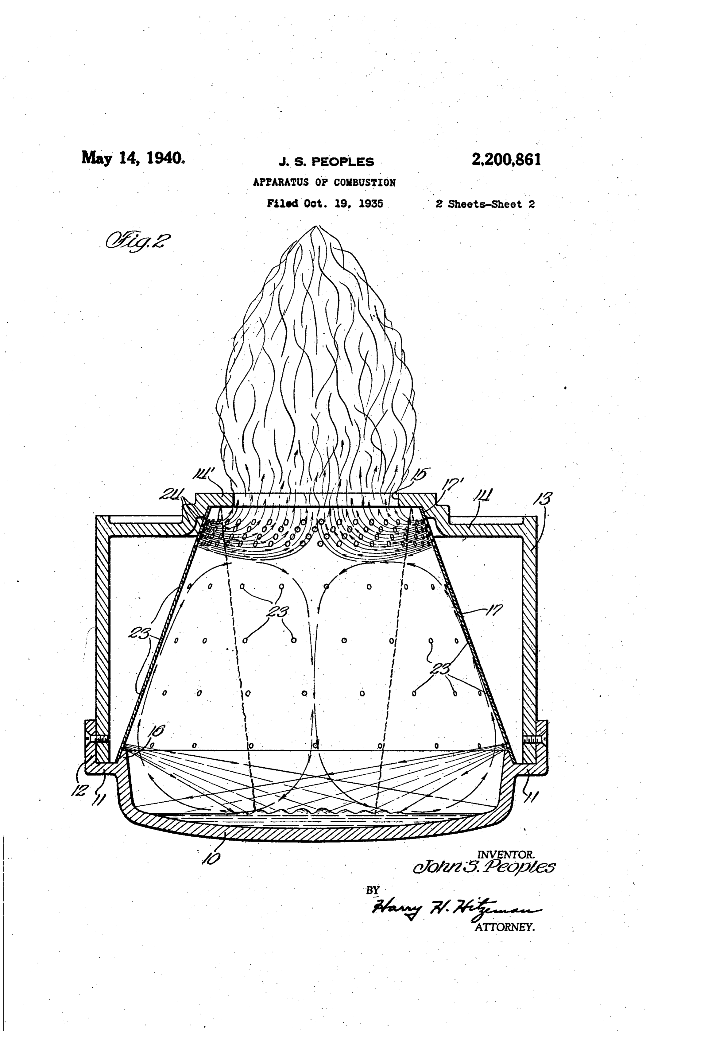
Fig. 1 is a longitudinal section through an oil It will be understood that the burner is pro burner embodying my invention; and vided with a Suitable pilot light which may be Fig. 2 is as sectional detailed . view on a con of any known or suitable type. I have illustrated siderably larger scale of the fire pot taken on the burner as being provided with an oil pilot of 35 the line 2-2 of Fig. 1, the manner in which the the type described and claimed in my co-pending oil is intermixed with the air being illustrated application, Serial No. 38,247, filed August 28,
Referring to the drawings, and particularly The cone 7 tapers in the upward direction to Fig. 1, the oil burner comprises a dish-like vessel a substantial degree. This cone is provided with 40 O which contains the oil being consumed. The perforations which are relatively sparse in the vessel 0 comprises an annular ledge which is lower portion of the cone and are relatively 40 provided with an upwardly directed bead, f2 with numerous in the upper portion of the cone. Thus in which is received the cylindrical wall of an air
I may provide four rows of perforations 23 at housing 3. The housing 3 is secured to the various heights, each of which comprises a rela 45 vessel 0 by any suitable means, for example,
SCreWS. tively small number of openings distributed uni formly around the circumference of the cone.
The upper end of the cylindrical housing 3 is Adjacent the upper edge of the cone I provide provided with an integral annular wall 4 which a plurality of rows, for example four, of similar is preferably stepped adjacent its inner edge as openings 24, very close together, each row com 50 shown in Figs. 1 and 2. It will be noted that the wall f4 provides a central opening 5 whichprising many more openings than those rows be low. The angle of the cone is sufficiently steep is Substantially smaller than the dish-shaped that the air projected from the openings of the vessel 10 located below it. lowest row are able to hit the body of oil main On its inner side the ledge is provided with tained in the vessel 0 in the manner shown in 55 a bead 6 which surface has a seat for the lower Fig. 2. 55
Page 4
The jets of air entering from the lowest row of the cone may be made of very thin metal with openings impinge against the surface of the oil out danger of burning Out.
in the vessel 0 at positions short of the center. It is to be noted that the characteristic opera All these jets of air, after impinging on the sur tion of the present burner is based upon the face of the oil, pass over said surface towards the supply of air under substantial pressure to the center, wiping the surface of the liquid oil and lowermost row of openings 23. It is this substan carrying oil vapors with them. The air and the tial pressure that produces jets strong enough to oil vapors rise upwardly through the cone and reach the surface of the oil and impinge there are augmented by the air jets introduced by the against with sufficient force to materially aid in ? other openings 23. The amount of air introduced the carburetion process. . . . . 0. by the openings 23 is sufficient to provide a com Although the present invention has been de bustible mixture of air and oil vapor. The oil scribed in connection with a specific embodiment vapor is not, however, consumed until it receives of apparatus and the preferred manner of opera the large amount of air supplied by the numerous tion of the process of combustion, it must be 5 openings 24. The openings 23 of the rows above understood that I do not intend to be limited to 5 the lowest, supply jets of air under pressure the specific details shown except insofar as set which are also directed downwardly and some of forth in the following claims. Having thus de these jets also wipe the surface of the oil in the scribed my invention, I declare that what I claim vessel 0. The jets of air wiping the Surface of S. ;?
20 the oil materially aid in its evaporation and in 1. An oil burner comprising a vessel for main 20 the maintenance of the body of oil at a tempera taining a body of oil, a perforated cone above said ture which avoids cracking and the formation of vessel and tapering upwardly therefrom, a reflect carbon. The upper openings 23 also create tur ing member above the cone and projecting in bulence of the mixed air and vapors and render wardly thereof for a substantial distance in the the mixture uniform in preparation for its upward radial direction, means establishing an annular 25 passage through the zone of high aeration consti chamber around said cone, and a blower for Sup tuted by the numerous openings 24 at the upper plying air under pressure to said annular chamber edge of the cone. to cool the cone, said chamber terminating short In Fig. 2 I have illustrated diagrammatically of the oil containing vessel to avoid undue cooling 30 the manner in which the jets of air from the thereof the perforations of the cone being ar 30 lowermost openings 23 impinge against the Sur ranged to direct air from the blower downwardly face of the oil and move thereover. In this figure into the oil containing vessel. N I have also shown a zone of rapid combustion 2. An oil burner comprising a dish-like vessel around the openings 24. The amount of air ad upon for maintaining a body of oil, a cone mounted mitted by these openings is so large that it tends and above said vessel and tapering upwardly 35 to create an eddy current in the form of a gyrat therefrom, said cone being provided with openings ing annullus within the cone T. This gyration of for the admission of air, walls around the cone the non-explosive gases together with the agitat and in spaced relation thereto, establishing an ing effect of the jets entering through the open annular air chamber around the cone and above ings 23 maintain the non-explosive gases in a the vessel, and a blower to supply air to the annu 40 very perfect state of uniformity and turbulence lar air chamber which passes forcibly through the and prevent the occurrence of isolated highly openings of the cone, said cone and its openings oxygenated zones which might occasion cracking being arranged so that the jets of air admitted and the deposition of carbon. by certain of said openings impinge forcibly upon The large amount of air introduced by the the surface of the oil in said vessel. openings 24 creates a zone of fire around the 3. An oil burner comprising, a dish-like vessel upper edge of the cone and a column of fire pro for maintaining a body of oil, a cone mounted jects upwardly through and beyond the central upon and above said vessel and tapering upwardly opening (5. It will be noted that combustion therefrom, said cone being provided with openings within the burner proper is restricted to a rela for the admission of air, walls around the cone tively small area around and within the upper end and in spaced relation thereto, establishing an of the cone. I have diagrammatically shown in annular air chamber around the cone and above Fig. 2 the manner in which heat from this annulus the vessel, and a blower for supplying air to the of flame is effectively reflected by the annular annular air chamber which passes forcibly 5 portion 4' of the wall f4 which projects inwardly through the openings of the cone, said cone and beyond the inner edge of the cone. The heat its openings being arranged so that the jets of air radiated downwardly by the annulus of the flame admitted by certain of said openings impinge and also the heat reflected downwardly by the forcibly upon the surface of the oil at positions. annular portion 4 under ordinary conditions is short of the center of said vessel. 60 sufficient to maintain the oil in the chamber 0 at 4. An oil burner comprising a shallow vessel for 60 a sufficiently high temperature to effect its vapor maintaining a body of oil, an upwardly tapering ization, particularly when aided by the forcible cone mounted upon and above said vessel, means surface wiping effected by the jets of air admitted at the upper end of said cone defining an issuing by the lowermost row of openings 23. throat, means enclosing an air chamber around The cone f7 can be very easily fabricated from said cone, a blower for supplying air under pres a blank of appropriate shape. This blank may be sure thereto, said cone being provided with open bent so as to bring its edges into overlapping rela ings for admitting air jets under pressure, the tion. These edges are then secured together by slope of the cone and the location of the lower Welding or any other suitable means. The cone most openings being arranged so that the perpen () may be made of relatively light metal, prefer diculars to the surface of the cone at their loca ably heat resisting steel. This cone is maintained tions strike the oil level short of the center of the at a remarkably low temperature owing to the vessel.
continuous supply of comparatively cold air 5. An oil burner comprising a lower member around the exterior surface of the cone. As a including a relatively shallow vessel for contain 5 result of this efficient cooling, I have found that ing a body of oil, an upwardly tapering perforated
Page 5
cone resting thereon, an upper member above said lower edges of said cone, said cone having a row cone connected to said lower member to provide of sparsely located openings adjacent its lower an air chamber around saidicone, and a reflecting edge and rows of sparsely located openings at flange extending inwardly for a substantial dis- varying heights on the cone and a plurality of tance in the radial direction beyond the upper e adjacent rows of closely located openings adja- is edge of the cone, said members being provided cent its upper edge.
with seat formations engaging the upper and JOEN S. PEOPS.

Provenance
- Collection
- Cited prior art
- Original PDF
- patentimages.storage.googleapis.com →
- Filed
- 1935-10-19
- Pages
- 5
- Method
- pdftotext (the PDF's own text layer) + pdftoppm 300dpi page scans
- Source
- Google Patents bibliographic record
- Granted
- 1940-05-14
- Inventors
- John S Peoples; SANGSTON HETTLER
- Transcribed from
- patentimages.storage.googleapis.com →