patent · US2214403
Vaporization control for liquid fuel burners
10 September 1940
Page 1
Drawing sheet — no readable text.
Page 2
Drawing sheet — no readable text.
Page 3
Patented Sept. 10, 1940 2,214,403
UNITED STATES PATENT OFFICE
vAPoRIZATION CONTROL FoR LIQUID
FUEL BURNERs
LeeKessler, s. Chadwick, Shaker Heights, and Charles J.
Cleveland Heights, Ohio, assignors to
Perfection corporationstoye of OhioCompany, Cleveland, Ohio, a
Application April 21, 1937, serial No. 138,168
to combine with a pot or bowl type burner, means
This invention relates to liquid fuel burners, and for distributing the air supplied thereto for com more particularly to those of the so-called pot or bustion purposes in various relations to the pot bowl variety wherein vapors are generated from or bowlso as to alter its cooling influence thereon a pool of fuel maintained in the bottom of the and thereby control the temperature of the pot 5 bowl, by heat produced by the burner, and mix or bowl and consequently the temperature and With air admitted to the bowl to form a com
Scientifically developed burners of this variety arrangement,A further object is to provide a simple damper are designed to consume a predetermined amount disorder, for that is practically immune from controlling the passage of air lo of fuel of a given volatility in a definite period of
time according to the setting of a metering valve through different courses to the burner, the vapor that controls the flow of fuel to the bowl. Fur upon generating function of the burner depending ther, these burners are intended to operate effi the apportionment of the air to said differ ciently and economically under these conditions ent courses. . . . . . . . . . . . . . . . . 15 with practically complete combustion so as to . forA such further object is to provide a construction a damper that is adapted to standard produce a clean fire, relatively free from carbon. stove construction and may be simply and eco These favorable conditions, however, are de stroyed if a fuel is used that differs perceptibly nomically incorporated therein. is . A still further object of the invention is to pro in volatility from that wherewith the burner was vide, an adjusting lever for the damper that is 20 designed for use. . . . . . .. . . . . convenient of installation and manipulation and With prevailing burners of the class described, that desirably includes an indicator which, in if fuel that is more volatile than that prescribed. association with a suitable scale or the like, des for use. With the burner is employed there is an ignates the setting of the damper for the differ excess of VaporS, resulting in incomplete combus 25 tion, lower efficiency, smoky fire and consequent ent grades of fuel. . . . .
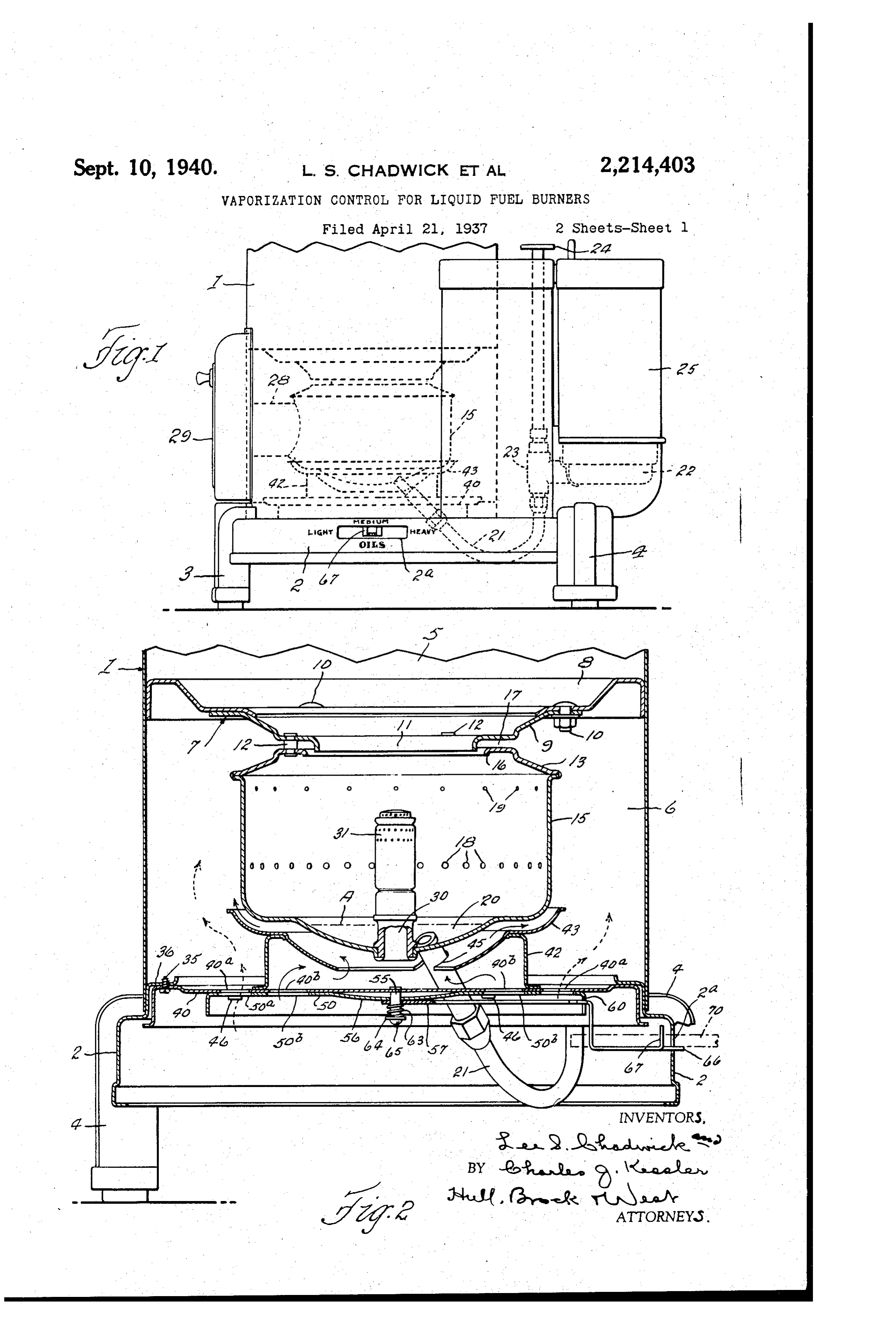
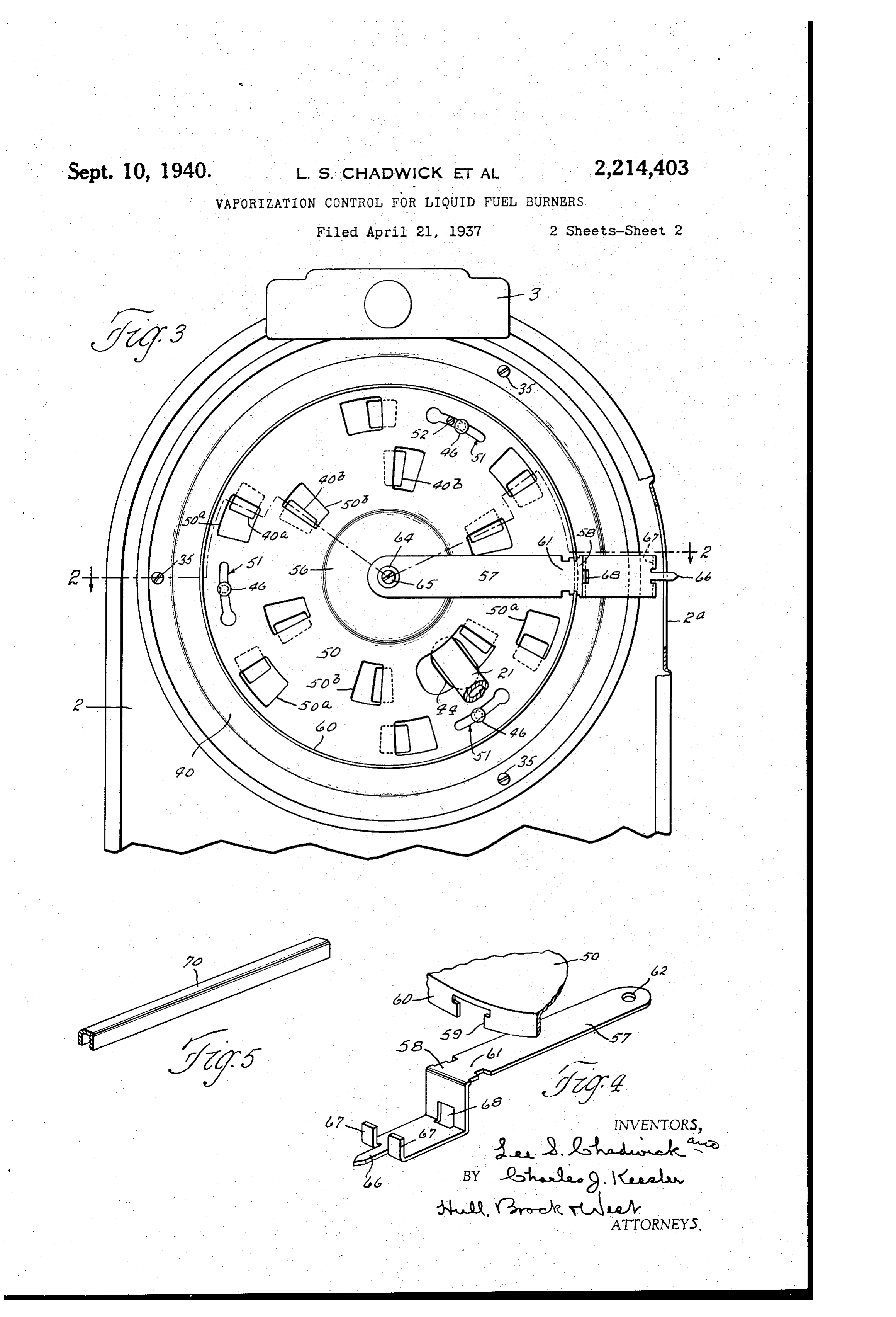
ly an undue accumulation of carbon in the burn The foregoing objects, with others hereinafter er; and if a heavier and less volatile fuel than appearing,illustrated that prescribed is used there is an insufficiency of invention are attained in the embodiment of the in the accompanying draw vapor, resulting in a slower rate of combustion or ings, wherein like reference characters, designate corresponding parts throughout the several-views. 30 30 fuel consumption, although there will be rela In the drawings, tively , complete combustion and clean; fire. In elevation of a liquid Fig. 1 is a fragmentary side both of these instances of abnormal conditions, porating our invention; fuel heating stove incor however, the thermal efficiency is less than would vertical section through the Fig. 2 is a transverse be the case if the burner were operating under lower portion of the stove, the plane of section being staggered as 35 35 normal conditions with the grade of fuel in indicated by the line 2-2 of Fig. 3; Fig. 3 is A broad purpose of our invention is to provide, a fragmentary bottom plan view: of the stove;
in a liquid fuel burner, means for administering Fig. 4 is a perspective view of the damper operat a cooling medium to a part of the burner that is ing lever with a fragment of the damper plate associated therewith, and Fig. 5 is a fragmentary 40 in heat exchanging relation to the fuel thereby perspective view of the detached lever operating to control the temperature and consequently the vaporization of the fuel. By virtue, thereof, fuels. member. . . . . . . . . . . . ... of different volatility may be burned efficiently, ourThe stove structure with which we have shown improvements associated includes a cylindri economically and satisfactorily, and at the de call drum? that is mounted on a base 2 supported 45 sired rate of combustion or fuel consumption.
A more specific object of our invention, is to a suitable distance from the floor by a front leg provide a burner of the pot or bowl variety with 3ofand rear legs. 4. These parts are 'constructed sheet metal of suitable gauge, and are fastened means for varying the temperature of a part of together by welding or any other approved means. the burner... that is in intimate heat exchanging The interior of the drum is separated into a 50 relation to the fuel (such part, in the embodi combustion chamber 5 and an air chamber 6 ment herein disclosed, being the bottom portion of the pot or bowl) according to the grade of fuel by a horizontally disposed partition designated . generally by the numerall. This partition con employed, so as to maintain the intended rate of sists of an annulus 8, having a peripheral flange
55 A still more limited object of our invention is that is welded or otherwise fastened to the drum, is
Page 4
and a ring-like member 9 that is attached by fuel is used, there is an excess of vapors, resulting bolts to to said aniulus, and whose inner edge is in incomplete combustion, lower efficiency, Smoky flanged downwardly to form a neck f . The fire, etc.; and if a heavier or less volatile fuel is member 9 is permanently secured, by rivets 2, used, there is an insufficiency of vapor, resulting to the annular top wall 3 of a burner pot or in a slow rate of combustion or fuel consump 5 bowl 5. The body portions of the rivets 2 space tion, although the combustion will be practically the member 9 from the top Wall 3 of the burner complete and the fire clean. In both instances, bowl, and the inner edge of Said top wall is however, the thermal efficiency will be less than turned downwardly slightly to form a lip 6 that when fuel of the prescribed grade is employed, 10 is in spaced relation to the neck ff. A passage whose volatility is suited to the temperature of 10 f7 is thus provided between the member 9, and the burner.
the top wall of the burner bowl through which From the foregoing description of the opera secondary air may enter the bowl from the sur tion of the burner it will be evident that vaporiza rounding air chamber 6, such air being deflected 5 downwardly into the bowl by the neck ff. So tion of the fuel may be controlled or, in other words, differences in the volatility of various called primary air is admitted to the interior of grades of fuel may be compensated for, by chang the bowl from said chamber through perforations ing the temperature of the burner, or, more spe 8 and 9 in the peripheral wall of the bowl. cifically, by altering the temperature of the bot The bottom wall of the bowl is shown as formed tom Wall of the burner, bowl. Our present inven 20 with a sump 20 to which liquid fuel is conveyed tion provides means for attaining this result, and 20 by a pipe 2 from a receptacle 22 with which the such means, as herein disclosed for illustrative pipe communicates through a metering valve 23, purposes, adapted to be operated by a handle 24. A reser will now be described.
voir 25 is suitably supported in an inverted posi Secured, as by Screws 35, to the inturned upper 25 end 36 of a cylindrical portion of the base, Over tion over the receptacle 25 and the outlet there which the bottom of the drum f is engaged, is 25 of is liquid Sealed in Said receptacle in accordance a stationary damper plate 40, the edge portion with common practice. By this well known ex of which is turned downwardly and then flanged pedient a maximum liquid level is established in outwardly to correspond, in cross Section gen the burner bowl or Sump, the Same being indi erally with the adjacent portion of the base 2. 30 cated by the line A. Access is had to the in This stationary burner plate has an outer series 30 terior of the burner bowl 5 for lighting and of segmental openings 40, and an inner Series clean-out purposes through a forwardly project of similar openings 40b, and mounted upon said ing sleeve. 28. A plug (not shown) fits within the plate between said Series of openings is an an sleeve 28 and forms a closure therefor, and the 35 same is adapted to be reached through an open nular partition 42 that Sustains a dish-shaped 35 ing in the front of the stove structure normally baffle 43 is provided With a notch 45 for the ac ly, the shape of the bottom Wall of the burner closed by a door 29. Air is also supplied to the bowl central interior of the burner bowl through an baffle 435. isThe plate 40 has a slot 44 and the air tube 30that opens through the bottom of the commodation of that with provided a notch 45 for th ac section of the pipe 2 that 40 bowl and has a perforated cap 3 applied to its is welded or otherwise permanently connected to 40
The structure thus far described is, generally the burner bowl. Buttons 46, that may be riveted or otherwise secured to the plate 40, speaking, that of a standard type of liquid fuel depend heating stove and constitutes no part of the pres damper from plate said plate and support a movable 50, having arcuate keyhole slots 45 ent invention except as it enters into the com 5f through which the buttons 46 are engaged. bination; and its operation, briefly, is as follows: Obviously, the movable damper plate may be With the metering valve 23-set, by means of the attached to the stationary damper plate by, en handle 24, to maintain a fire of the desired in gaging the enlarged ends of its slots 5f. over the tensity, fuel will flow from the receptacle 22 buttons 46 and turning the plate 50 to dispose 50 through the valve.23 and pipe 2 to the burner the buttons. Out of register: with the enlarged 50 bowl, attaining a level therein indicated by the ends of the slots; and to prevent the plate. 50 line A. To light the burner, the door'29 is opened from being turned to a position to align the but and the previously mentioned plug (not shown) is tons with the 'enlarged ends of the slots, a stop removed from the sleeve. 28 and a lighted match, 52 depends from the stationary burner plate 55 taper or other igniting means is entered through and Occupies. One of the slots between the en 55 the sleeve to ignite the fuel in the Sump 20, after larged end thereof and the corresponding but which the plug is replaced and the door 29 closed. ton 46.
As combustion progresses, the fuel is more rapidly . . The movable damper plate 50 has an outer vaporized and the vapors commingle with primary Series of segmental openings 50a and an inner air entering through the perforations 8 and 9 to form a rich mixture which, when joined by Series of similar openings 50b that are spaced 60 the secondary air entering through the passage radially from the center of the damper plates 7, burns with a clean flame that rises through like distances, respectively, with the series of the neck into the combustion chamber 5. Wery openings 40 and 40b of the stationary damper 65 Soon after the burner is lighted, the oil level re plate 40. The openings of the two plates are so cedes to a very low point on account of the in related that when the corresponding ones of the creased rate of evaporation due, in part, to the outer series of both plates are in register with relatively high temperature of the botton of the each other, the corresponding ones of the inner burner bowl or pot, and operation proceeds in a Series of the two plates are out of register, and Vice versa, these conditions being attained when 70 normal fashion. the movable damper plate is at the extreme 70 If liquid fuel is employed having a volatility limits of its movement; and when in any posi suited to the operating temperature of the burner, tion intermediate said limits, the openings of practically complete combustion is obtained re both series of the two plates are in overlapping sulting in a clean and efficient fire. As previously relation, the extent to which they overlap being 75 pointed out, however, if a lighter or more volatile determined by the adjustment of the movable
Page 5
damper plate. If the combined area or capacity light and more volatile fuel. By moving the lever of the openings of the respective inner and outer to the opposite end of the slot adjacent the mark series be equal, the total amount of air passing ing indicating heavy oil, the openings 40 and 50b through the damper will remain constant re are closed, and the openings. 40 and 50 are gardless of the damper adjustment; but if it brought into complete registration which causes were found advantageous to vary the amount of all air entering the chamber 6 to take the course of the dotted line arrows. In this case only an combustion air for different grades of fuel, this may be accomplished by making the area or ca insignificant portion of the air that enters the pacity of the openings of the two series differ chamber 6 will find its way between the baffle 43 10 ent and of the proper ratio. and the bottom wall of the burner bowl to satisfy O A stud 55 is secured to and depends from the the demands of the air tube 30, wherefore the center of the stationary damper plate 40 and bottom wall of the burner may attain its highest passes through an aperture in the depressed temperature which is required in the vaporiza central portion. 56 of the damper plate 50 and tion of the heavier fuel. When the adjusting 5 has journaled on its . . therebelow the inner end lever is in intermediate position, as illustrated in 5 of an operating lever 5, shown in perspective the drawings, the openings of the two series of in Fig. 4. A portion 58 of the lever 57 accurate both plates are in partial registration, as indi ly fits within the enlarged end of a T-shaped cated in Fig. 3, so that the air is divided sub notch 59 that is formed in the downturned stantially equally between the two courses indi 20 peripheral flange 60 of the damper plate 50, and cated by the full and dotted line arrows, thus20 to facilitate the insertion of the lever. Within causing the bottom of the burner bowl to be kept at a moderate temperature such as is suitable the notch, the former is reduced in width adja for cent the portion 58 to form a neck 6 f, the neck the proper vaporization of a medium grade being sufficiently less in width than the narrower oil. . ... w 25 part of the notch 59 to permit it to be readily Having thus described our invention, what we 25 engaged through said narrow part so as to claim is: - .. . .. register the portion 58 of the lever with the 1. In a liquid fuel burner, a burner bowl hav wider portion of the notch thereby permitting . ing means for admitting air thereto, means for the lever to be moved radially inwardly with delivering fuel to the bowl, means defining two 30 respect to the plate until the opening 62 at its passages for the air supplied to the bowl, one of 30 inner end is in a position to be engaged over said passages conducting the air in more inti the stud 55. The inner end of the lever is held mate heat exchanging relation than the other tightly against the adjacent portion 56 of the to a part of the bowl whose temperature influ movable damper plate, and the portion of said ences the vaporization of the fuel, and an ad 35 35 plate outwardly beyond its depressed portion 56 justable means for variably apportioning the air is held in firm frictional engagement with the to the two passages. . . . . . . . . . ; damper plate 40, by a Spring 63 that surrounds 2. In a liquid fuel stove including an air cham the stud 55 and is compressed between the lever ber, a burner bowl situated therein and arranged 57 and an abutment. 64 which may consist of a to receive combustion air therefrom, and means 40 washer: that is held to the end of the stud by a for delivering liquid fuel to the bowl; means Screw 65. The Outer end portion of the lever is defining two passages for the air admitted to said turned downwardly. and thence outwardly and chamber, one of said passages conducting the air terminates in a central index pointer 66 and in more intimate heat exchanging relation than laterally spaced upturned lugs 67, the former the other to a part of the bowl whose tempera projecting through a slot 2a in the side of the ture influences the vaporization of the fuel, and 45 base 2 for association with certain indicia that damper means common to both passages for is carried by the base adjacent the slot and con Simultaneously controlling the admission of air sisting, in the present instance, of the words thereto.
“Light-Medium-Heavy-Oils.'. The space be 3. In a liquid fuel stove including an air cham tween the aforesaid lugs 67 is in axial align ber, a burner bowl situated therein and arranged 50 ment with an opening 68 in the downturned por to receive combustion air therefrom, and means tion of the lever. By inserting the end of a for delivering liquid-fuel to the bowl; a station channel bar 70 (Figs. 2 and 5) through the slot alry damper plate constituting a wall of 3 said 28 and between the lugs 67 and into the slot 68 chamber, a movable damper plate sustained in 5 5 of the lever, the lever may be operated to adjust operative relation to the former damper plate, 55 the movable damper plate 50 with respect to the the damper plates having two series of cooperat Stationary damper plate 40 so as to effect the ing air openings so related that when the mov desired relation of the openings of the two able damper plate is shifted to close the openings plates. of either series those of the other series will be 60 When the lever is swung to the left, as the opened, and means defining. two passages ar 60. parts are viewed in Fig. 1, or toward the marking ranged to receive air, respectively, from the two on the base that indicates an adjustment of the Series of openings, one of said passages conduct damper that renders the stove suitable for use ing the air in more intimate heat exchanging with light fuels, the openings 408 and 50s are out relation than the other to a part of the burner (35. of register with one another and the openings bowl whose temperature influences the vaporiza 65 40 and 50 are in complete registration. Con tion of the fuel. " .. Sequently the air that is Supplied to the chamber 4. In a liquid fuel stove including an air cham 6 for combustion purposes is required to take the ber, a burner bowl situated therein and arranged course indicated by the full line arrows in Fig. 2, to receive combustion air therefrom, and means a Small part of said air incidentally entering the for delivering liquid fuel to the bowl; a station 70 burner bowl through the tube 30 while the major ary damper plate constituting a wall of said portion of it Sweeps outwardly between the baffle chamber, a movable damper plate sustained in 43 and the botom wall of the burner bowl, thus operative relation to the former damper plate, keeping the lower portion of the bowl at a rela the damper plates having two series of cooperat, tively low temperature which is desirable for the ing air openings so related that when the mov 76
Page 6
able damper plate is shifted to close the openings series of openings for cooperation with the open of either series those of the other series will be ings of the stationary damper plate, all series of opened, means defining two passages arranged openings being substantially concentric to the to receive air, respectively, from the two series of axis of rotation of the movable damper plate, the openings, one of said passages conducting the openings being SO arranged and related that 5 air in more intimate heat exchanging relation W.hen those of either series are closed those of the than the other to a part of the burner bowl Whose other Series Will be open and So that the Openings temperature influences the vaporization of the of both plates of the two series are in Overlapped fuel, means for adjusting the movable damper relation when the movable damper plate occupies O plate, and an indicator associated thereWith for any position between its two extreme positions, O designating the different positions of damper ad an annular partition rising from the Stationary iustment. damper plate between the inner and outer Series 5. In a liquid fuel stove including an air cham of openings, a baffle Supported by, Said partition ber, a burner bowl situated therein and arranged in Spaced relation to the bottom wall of the burner s to receive combustion air therefron, and means bowl and having an opening inside the confines 5 for delivering liquid fuel to the bowl; a stationary of said partition, an adjusting lever Supported damper plate constituting the bottom Wall of the to swing on the axis of rotation of the movable air chamber and having an outer Series of open damper plate, a part of the movable damper plate ings and an inner series of openings, a movable adjacent its periphery being turned downwardly 20 damper plate connected to the Stationary damper and having a T-shaped notch, the adjusting lever 20 plate for rotary movement and having corre being reduced in Width to form a neck adapted sponding series of openings for cooperation. With to be engaged through the narrow portion of said the openings of the stationary damper plate, all notch, which neck is out of register with the series of openings being substantially concentric notch when the pivotal axis of the lever is coin to the axis of rotation of the movable damper cident with the axis of rotation of the novable 25 plate, the openings being so arranged and related damper plate, the Outer end of the ever being that those of one series are closed when those of designed to receive a detached operating the other series are open, and vice versa, whereby member.
the openings of both plates of the two Series are 8. In a liquid fuel stove including an air cham 30 in overlapped relation when the movable damper ber, a burner bowl situated therein and arranged 30 plate occupies any position between its two ex to receive combustion air therefrom, and means treme positions, an annular partition rising from for delivering liquid fuel to the bowl; a stationary the stationary damper plate between the inner damper plate constituting the bottom wall of the and outer series of openings, a bafile Supported by air chamber and having an outer series of open 35 said partition in spaced relation to the bottom ings and an inner series of openings, a movable 35 wall of the burner bowl, said baffle having an damper plate connected to the stationary damper opening inside the confines of Said partition, and plate for rotary movement and having corre means for adjusting the movable damper plate. Sponding Series of openings for cooperation with 6. In a liquid fuel stove including an air cham the openings of the stationary damper plate, all ber, a burner bowl situated therein and arranged Series of openings being substantially concentric 40 to receive combustion air therefrom, and means to the rotational axis of the movable damper for delivering liquid fuel to the bowl; a stationary plate, the openings being so arranged and related damper plate constituting the bottom Wall of the that when those of either series are closed those air chamber and having an outer series of Open of the other series will be open and so that the ings and an inner series of openings, a movable Openings of both plates of the two series are in damper plate connected to the stationary damper overlapped relation when the movable damper plate for rotary motion with respect thereto and plate occupies any position between its two ex having corresponding series of Openings for co treme positions, an annular partition rising from operation with the openings of the stationary the stationary damper plate between the inner damper plate, all, series of openings being Sub and outer Series of openings, a baffle Supported by 50 stantially concentric to the axis of rotation of the Said partition in Spaced relation to the bottom movable damper plate, the Openings being SO ar wall of the burner bowl and having an opening ranged and related that when those of either within the confines of said partition, an adjust series are closed those of the other Series are open ing lever Supported to swing on the rotational 55 and so that the openings of both plates of the two axis of the novable damper plate and connected 55 series are in overlapped relation. When the mov to said plate, the outer end of the lever being pro able damper plate occupies any position between vided with a pointer, and indicating means on the its two extreme positions, an annular partition Stove structure wherewith said pointer cooperates rising from the stationary damper plate between to designate the different positions of damper 80 the inner and outer series of openings, a baffle adjustment. - 60 supported by said partition in Spaced relation to 9. In a liquid fuel stove including an air cham the bottom wall of the burner bowl and having an ber, a burner bowl situated therein and arranged opening within the confines of said partition, and to receive combustion air therefrom, and means a lever arranged to Swing on the axis of rotation for delivering liquid fuel to the bowl; a station 65 of the movable damper plate and having connec alry damper plate constituting a wall of the air tion with said plate for adjusting it. chanber and having, two series of openings, a 7. In a liquid fuel stove including an air cham novable damper plate associated with the sta ber, a burner bowl situated therein and arranged tionary damper plate and having corresponding to receive combustion air therefron, and means Series of openings for cooperation with the open 70 for delivering liquid fuel to the bowl; a stationary ings of the stationary damper plate, the open damper plate constituting the bottom Wall of the ings being SO arranged and related that those of air chamber and having an Outer Series of open One Series are closed. When those of the other Se ings and an inner series of openings, a movable ries are open, and vice versa, whereby the open damper plate connected to the stationary damper ings of both plates of the two series are in over plate for rotary motion and having Corresponding lapped relation. When the movable damper plate 75
Page 7
occupies any position between its two extreme stantially concentric to the rotational axis of the movable damper plate, the openings being so ar positions, air directing means defining two pas sages wherewith the openings of the respective ranged and related that those of one series are series communicate, the movable damper plate closed when those of the other series are open, having keyhole slots, and buttons carried by the and vice versa, whereby the openings of both stationary damper plate occupying said slots, the plates of the two series are in overlapped rela enlarged ends of the slots being ample to permit tion when the movable damper plate occupies the passage of the buttons therethrough while any position between its two extreme positions, the body portions of said slots are of less width air directing means rising from the stationary damper plate between the inner and outer series O
O than the buttons, and stop means for preventing of openings and having its upper portion in the movable damper plate from assuming a posi tion wherein the buttons register with the en Spacedbowl, relation to the bottom wall of the burner the movable damper plate having arcuate larged ends of the slots. keyhole slots, buttons carried by the stationary 5 I0. In a liquid fuel stove including an air damper plate occupying said slots, the enlarged 5 chamber, a burner bowl-situated therein and ar ends of the slots being ample to permit the pas ranged to receive combustion air therefrom, and Sage of the buttons therethrough while the body means for delivering liquid fuel to the bowl; a sta portions of said slots are of less width than the tionary damper plate constituting the bottom buttons, wall of the air chamber and having an outerse stationaryand stop means depending from the damper plate and occupying one of the ries of openings and an inner series of openings, slots intermediate the enlarged end thereof and a movable damper plate connected to the sta tionary damper plate for rotary movement and the corresponding button.
having corresponding series of openings for co LEE s. CHADWICK. Operation with the Openings of the stationary CHARLES J. KESSLER. 26 25 damper plate, all series of openings being sub
Provenance
- Collection
- Cited prior art
- Original PDF
- patentimages.storage.googleapis.com →
- Filed
- 1937-04-21
- Pages
- 7
- Method
- pdftotext (the PDF's own text layer) + pdftoppm 300dpi page scans
- Source
- Google Patents bibliographic record
- Granted
- 1940-09-10
- Inventors
- Lee S Chadwick; Charles J Kessler; Perfection Stove Co
- Transcribed from
- patentimages.storage.googleapis.com →