patent · US2466563
Pot type oil burner with a circumferential vaporizing chamber
5 April 1949
Page 1
Drawing sheet — no readable text.
Page 2
Drawing sheet — no readable text.
Page 3
Patented Apr. 5, 1949 2466,563
UNITED STATES PATENT OFFICE
POT TYPE OL BURNER WITH A CBCUM
FERENTA, WAPOBANG CBAMBER,
Edward R. Stempel and Marcus Nelson, Albert
Lea, Minn., assignors to American Gas Machine
Company, Albert Lea, Minn., a corporation of
Minnesota C
Application July 27, 1945, serial No. 607,382
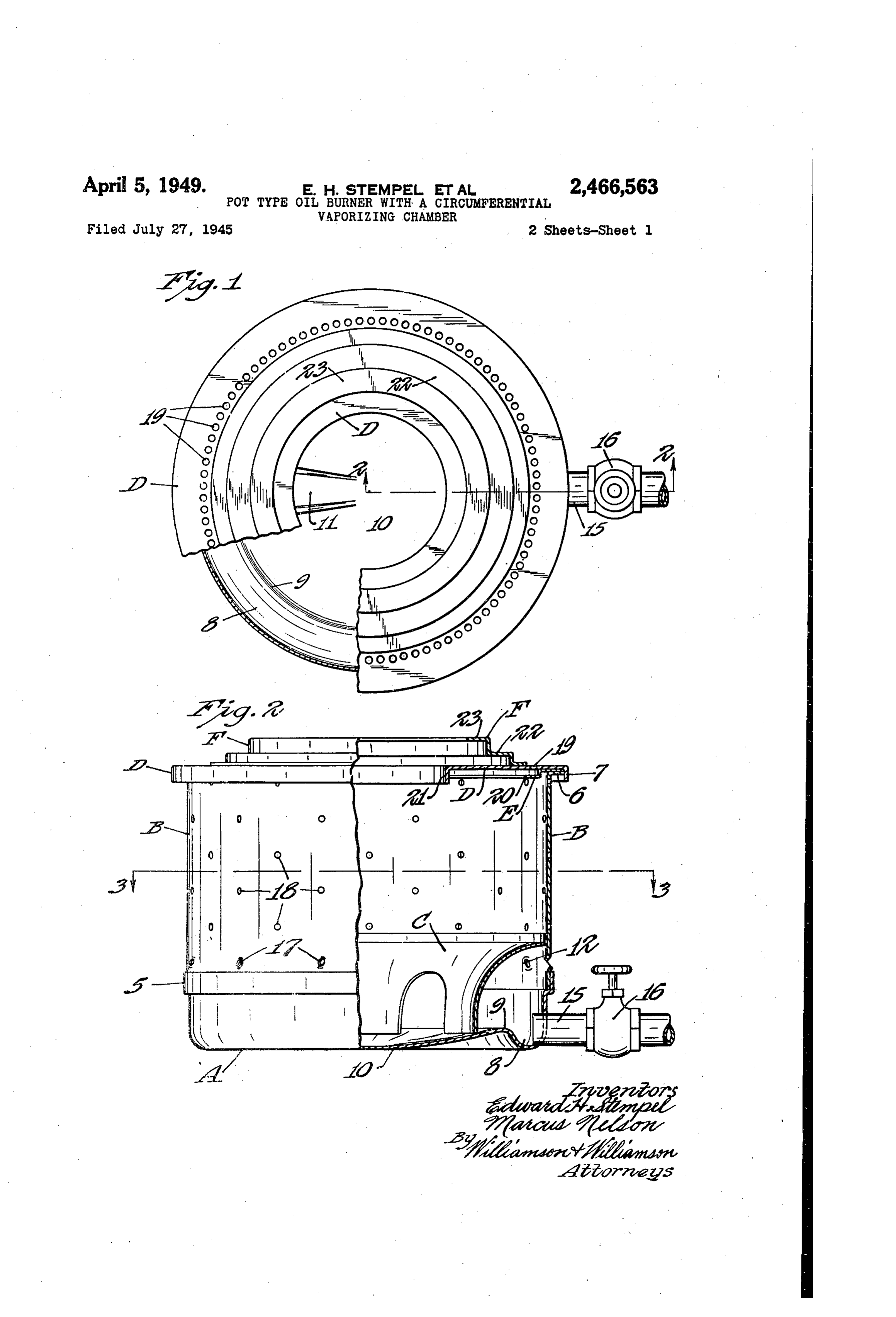
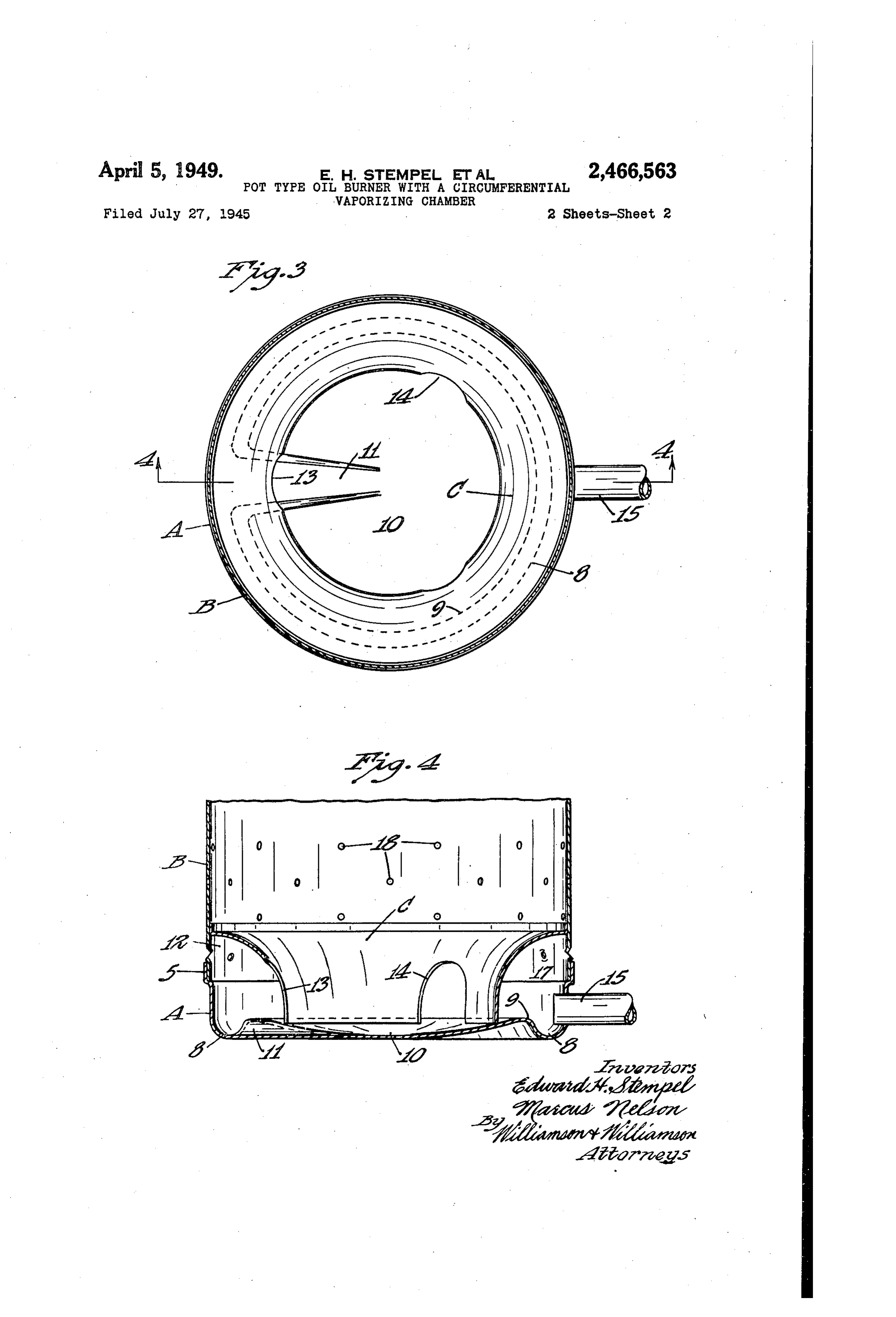
This invention relates to oil burners of the pot secured together to better hold their positions type. as by spot welding, riveting or the like. It is one of the objects of the invention to pro The pot bottom A at its Outer lower portion is vide a novel and improved pot-type oil burner of Curved to form an annular trough 8, the inner cheap and simple construction which can be wall of which forms a rib or dam 9 spaced above burned at pilot flame, intermediate flame and the level of the bottom of the trough 8 and ex high flame depending upon the amount of oil tending through approximately 340 degrees of a supplied to the burner. circle. Also, the dam 9 forms the upper edge of Another object is to provide in a pot-type oil a concavely curved dish O which closes the burner improved means for introducing second 10 central part of the pot bottom A and which is ary combustion air to the pot, whereby the op at least as deep as the trough 8. At the point eration of the burner at high flame is greatly where the pot bottom A is not pressed up to form improved. - . a continuation of the dam 9 the post bottom is
. The objects and advantages of the invention curved downwardly to form a channel lead will more fully appear from the following de 5 ing from the trough 8 to the center of the dish O scription, made in connection with the accom and, as will be clearly seen from Fig. 4 of the panying drawings, wherein an exemplification drawings, the lower part of this channel is of the invention is shown and wherein like ref as deep as the trough 8 so that any liquid flow erence characters refer to the same or similar ing around the trough 8 to the channel may parts throughout the various views, and, in 20 pour therethrough into the central part of the which: dish fo.
Figure 1 is a plan view of the oil burner, Cer The cowl, C as shown, extends upwardly tain of the parts being broken away and others through roughly, a third of the height of side shown in section to more clearly illustrate the wall B and is provided with an upturned flange construction thereof; 25 at its upper end which fits with close clearance Figure 2 is a view partly in side elevation and the interior of the wall B. From said flange partly in vertical section through the oil burner, cowl C curves inwardly and downwardly to con part of the drawing shown insection being taken tact, the dish O in somewhat in Wardly spaced substantially on the line 2-2 of Figure 1: relation to the annular dam 9. The COwl C, the Figure 3 is a horizontal section taken on the 30 outer part of the pot bottom A, and the lower line 3-3 of Figure 2; and part of the side wall B thus form an annular Figure 4 is a detailed view in vertical section chamber 12 which will be called a vaporizing taken on the line 4-4 of Figure 3 as indicated chamber in accordance with its function. Imme by the arrows. diately above the channel f, the cowl C is While the pot of the oil burner can be variously 35 deeply notched upwardly to form with a portion of the channel if a passage 3 affording com constructed, there is in accordance with the ill lustrated embodiment, an entire pot bottom A munication between the chamber 2 and the Cen formed of one piece of metal, a tubular side wall tral part of the pot above the dish O. At cir B formed of a second piece, a cowling C formed cumferentially spaced points from each other of a third piece, a deflector ring D formed of a 40 and from the channel 3 the cowl C is notched fourth piece, an air director ring E formed of a upwardly from its lower edge to form one or fifth piece and a flame confining ring F formed more additional passages 4 in cooperation with of a sixth piece. The pot bottom A is provided the dish O and also affording Communication at its side near its upper edge with an offset between the vaporizing chamber 2 and the cen flange 5 within which the side Wall B is re tral part of the pot above the dish O. It should ceived, and the side wall B is provided at its be noted that the lower parts of the passages 4 top with an out-turned flange 6 on which the are well above the level of the channel f for air director ring E rests. The air deflector ring D a purpose to presently appear. In actual practice in turn, rests on the air director ring E and pro the notches in the cowl plate C and forming por jects well inwardly therefrom, and at its outer 50 tions of the passages 3 and 4 are Set circum edge, the air director ring is equipped with a ferentially at 120° from each other although this down-turned flange which encompasses the is not absolutely necessary. outer edges of the flange. 6 and the air director Affording communication with the vaporizing ring E. The flame confining ring Frests on the chamber 2 at a point diametrically opposite the air deflector ring D and extends to a point abovepassage 3 is an oil delivering conduit 5 for sup it. In practice, the parts may be permanently 55 plying liquid hydrocarbon from a source of sup
Page 4
ply to the pot. The flow of oil through the Con highly heated. Eventually this heat will be suf duit 5 may be controlled in any desired manner ficient so that the small quantity of oil supplied to vary the quantity of flow and for ease in ill through the channel for low flame operation will lustration there is merely shown in the illustrat be very largely vaporized within the chamber 12, ed embodiment a hand-controlled valve 6 for the oil being completely vaporized before it this purpose. In commercial installations other reaches the central part of the dish O. By cut controls will be employed such as are commonly ting off the supply of fuel to a greater extent as used in conjunction with other oil burners now by manipulating the valve 6 to a more closed on the market. position the burner will operate so as to vaporize Below the level where the cowling C is attached O all of the oil before the oil has traveled around to the side wall B the side wall is provided with the trough 8 from its admission point through a multiplicity of perforations circumferentially the conduit 5 past one or both of the passages spaced from each other and forming openings 4. In other words, vaporized fuel in small quan leading into the vaporizing chamber 2 and sup tities will then issue from one or more of the plying vaporizing air thereto. In order that the s passages 4 and burn as issued therefrom, thereby air admitted through the openings into the forming a pilot flame for ignition when greater chamber 2 may be better directed downwardly quantities of fuel are admitted to the burner to to mix with oil in the trough 8, at the time the Operate it either at low flame, intermediate flame openings are formed, the metal is perforated in or high fame.
a downwardly and inwardly angular direction as 20 With our improved structure, a substantially is well known in the art. infinite number of flames and consequently, heat Above the level where the cowl plate C joins generating intensities may be obtained progres the side wall B, and at several different levels, sively from the low, pilot flame to the high flame primary combustion air openings 8 are formed dependent upon the adjustment of the regulating in the side wall B, air from these openings running 26 valve 6 and the control of fuel introduced into the central part of the pot above the dish O. through conduit 5, per unit of time. The deflector ring D near its edge but in Wardly To operate the burner at high flame a greater from the side wall B is provided with a multi quantity of fuel is supplied through the fuel con plicity of vertical openings 9, and these openings duit 5 as by opening the valve 6 widely and grad are for the purpose of supplying secondary COm 30 ually the burner goes successively from pilot flame bustion air for high flame operation of the burner. operation to low flame operation and then to high It will be noted that the air must pass through flame operation. The oil supply at this time is these openings 9 in a downward direction. The too much to be entirely vaporized within the air director ring E has a flange 20 spaced a short vaporizing chamber 2 and it passes in two distance below the deflector ring D and imme 35 branches completely around the trough 8 to pour diately below the secondary air inlet openings through the channel f f into the central part of 9, and this flange 20 acts to direct the air run the dish O. There it is supplied with primary ning through the openings 19 inwardly of the air admitted to the interior of the pot through burner so this air takes a diagonally downward the openings 8. Gradually the flame rises in and inward course. The deflector ring D has a 40 the burner so that it extends well up into the downwardly extending flange 2 at its inner edge upper part of the pot and is then supplied with which also has some air deflecting action and secondary air admitted through the secondary tends to prevent straight horizontal movement air openings 19. Because of the direction that of air from the secondary air openings 9 to the 45 this secondary air must take by reason of the center of the burner. vertical disposition of the openings 9, the air The flame confining ring F is attached to the director ring E and the flange 2, the secondary deflector ring D preferably just inwardly of the air works into the flame in a downwardly and openings 9 and it has a first step 22 which is inwardly extending direction, thereby mixing with inwardly directed and which is spaced a short 50 the products of combustion within the pot to a distance above the deflector ring D and has a greater extent and more thoroughly than is the second step 23 which is spaced above the step 22 case in burners wherein the secondary air is di and also inwardly directed. The ring F functions rected upwardly and inwardly. The ring F tends to confine the flames when the burner is in high to confine the flame by its two steps 22 and 23 flame operation and prevent flames from spread ing outwardly to too great an extent. 55 when the burner is in high flame operation. In the operation of the burner the burner will It will be seen that a highly efficient, simple normally be lighted as by throwing a small scrap and economical pot type oil burner has been provided, of paper or a match into the pot when sufficient oil is being supplied as by controlling the valve It will, of course, be understood that various 6 for low flame Operation. As the valve 6 is 60 changes may be made in the form, details, ar opened oil will be supplied to the conduit 5 into rangement and proportions of the various parts the trough 8 and will flow out after making the without departure from the scope of the present circuit of the trough through the channel if into invention which generally stated, consists in the the central part of the dish O. When sufficient matter shown, described, and set forth in the oil has been accumulated this oil may be lighted 65 appended claims.
by a match or paper as aforesaid. Some air will What we claim is:
be supplied through the openings T, chamber 2 1. An oil burner comprising, a pot bottom hav and passages 3 and f4 to supply this initial igni ing an annular trough in its outer portion, the tion, but the major part of the air will be supplied inner wall of which trough forms a dam through through the primary air supply openings 8. 70 Out most of the circumference of the pot bottom, After the burner has operated at low flame for a said pot bottom being depressed inwardly from time with the flame confined well within the lower said dam to form a dish, and the inner wall of part of the pot, the lower part of the pot will Said trough being depressed at one point between become highly heated and, Of course, the air portions of said dam to form a flow channel from within the vaporizing chamber 2 will also become 75 the lower part of said trough to the lower part of
Page 5
said dish, an annular side wall upstanding at the forming an outer vaporizing chamber in the outer side of said pot bottom, said annular wall lower portion of the pot, there being an upstand being perforated at various levels to form open ing dam in the lower portion of said chamber ings for air admission above said trough and also spaced inwardly from the outer portion thereof openings for primary combustion air to the inte and forming an oil trough in said chamber, a rior of the pot, a cowling joining said side wall dish inwardly from said dam and running to at and the upper part of said dish above certain of least the depth of said trough, first passage means said openings and combining with portions of said between said chamber and said dish including an pot bottom and Said side wall to form a vaporiz oil passageway through said dam, the lower ing chamber, said cowling having openings there 0. part of the passage formed by said first passage in at three circumferentially spaced points, one means being located at a level at least as low as of which openings is located directly above said the lower level of said trough, second passage channel to form with said channel a first pas means Spaced along said trough from said first sage from Said chamber to the interior of the pot passage means and affording communication from above the dish and the other openings forming said chamber to said dish at a level well above second passages above the dam level from said the lowest level of said first passage, a valve con chamber to the interior of the pot above said dish, trolled conduit for delivering liquid fuel from a a valve controlled oil conduit for delivering liquid source of supply and communicating with said fuel from a source of supply to said chamber, said trough at a point more adjacent to said second oil conduit delivering into said chamber at a point passage means than to said first passage means, remote from Said first paSSage and between said means for supplying air to said chamber, means two second passages, an in Wardly directed deflect for supplying primary combustion air to said pot, and means in the upper part of Said pot for sup ing ring resting on said side wall at the top of the pot, and means for delivering Secondary combus 2 5 plying secondary combustion air. 5. An oil burner comprising a pot having an tion air at the upper portion of the pot. Opening in its upper portion and including means 2. An oil burner comprising a pot having a forming an outer annular vaporizing chamber in closed bottom and an Opening in its upper por the lower portion of the pot, there being an up tion and including means forming an outer cir cumferential vaporizing chamber in the lower standing dam in the lower portion of said cham ber spaced inwardly from the outer portion there portion of said pot, said chamber extending Sub 30 of and forming a trough in said chamber, a con stantially entirely around the bottom of Said pot, cave dish joining said dam and inwardly dis there being an upstanding dam in the lower por posed therefrom, said dish running to at least tion of said chamber spaced inwardly from the the depth of said trough, first passage means af outer portion thereof and forming an oil trough fording communication between said chamber within the chamber, a dish inwardly from said and the interior of said pot above said dish in dam, passage means including an oil paSSageway cluding an oil passage from said trough through through said dam affording communication be said dam, the lower level of the first, passage tween said chamber and said dish, valve con formed by said first passage means being at least trolled conduit means for delivering liquid fuel as low as the lower level of said trough, second from a source of supply to said chamber, said passage means affording communication between conduit means communicating with the trough said chamber and the interior of said pot above in said chamber at an area of said trough that said dish and spaced along said trough from said is in non-communication with the oil passageway first passage means, the lower level of the passage through said dam for at least Substantially half formed by said second passage means being well the extent of the trough, means for Supplying above the lower level of said first passage, a valve air to said chamber, means for supplying primary controlled oil conduit for delivering liquid fuel combustion air to said pot and means in the upper part of said pot for supplying secondary combus communicating of from a source supply to said chamber and with said trough at a point more tion air. closely adjacent said second passage means than 3. An oil burner comprising a pot having an 50 Said first passage means, means for supplying air opening in its upper portion and including means to said chamber, means for supplying primary forming an outer vaporizing chamber in the combustion air to the interior of said pot, and lower portion of the pot and having an upstand means for Supplying secondary combustion air ing dam in the lower portion of said chamber at the upper portion of said pot. spaced inwardly from the outer portion thereof 6. An oil burner comprising a cylindrical pot and forming an oil trough in said chamber, a dish having an opening in its upper portion and hav inwardly from said dam, first passage means ing means forming an outer annular vaporizing tween said chamber and said dish including an chamber in its lower portion and having an up oil passageway through said dam, second passage 60 standing means between said chamber and said dish above dam in the lower portion of said cham the lowest level of said first passage means and ber spaced inwardly from the outer portion spaced along said trough from said first passage thereof and forming a trough in said chamber, means and affording communication from Said a concave dish joining the said dam and inward chamber to said dish at a level well above 65 ly disposed therefrom, said dish running to at the lowest level of said first passage, a valve Con least the depth of said trough, first passage trolled conduit for delivering liquid fuel from means affording communication between said a source of supply and communicating with said chamber and the interior of said pot above said trough at a point more adjacent to said Second dish including an oil passage from said trough passage means than to said first passage means, through said dam, the lower level of the first pas means for supplying air to said chamber, means 70 Sage formed by said first passage means being for supplying primary combustion air to said pot, below the level of said dam, a pair of second pas and means in the upper part of said pot for sup sage means affording communication between said chamber and the interior of said pot above plying secondary combustion air.
4. An oil burner comprising a pot having an said dish, the lower level of the second passages opening in its upper portion and including means 75, formed by the said second passage means being
Page 6
half the extent of the trough and at a point more above the level of said dam, and said second pas adjacent sage means being circumferentially Spaced from to said second passage means than to each other and from said first paSSage meals, a said first passage means, means for supplying valve controlled oil conduit for delivering liquid air to said chamber, means for supplying primary fuel from a source of supply and communicating combustion air to said pot, and means in the up with said chamber between said two Second pas per part of said pot for supplying secondary con sage means at a point remote from said first pas bustion air.
sage means, means for supplying air to said EDWARD H. STEMP, chamber, means for supplying primary combus MARCUS NSON. tion air to said pot, and means in the upper part O of said pot for supplying secondary combustion REFERENCEs CITED air. The following references are of record in the 7. An oil burner comprising a pot having a file of this patent:
closed bottom and an opening in its upper por tion and including means forming an Outer cir 5 UNITED STATES PATENTS cumferential vaporizing chamber in the lower Number Name Date portion of the pot, said chamber extending Sub Re, 22,332 Sabins ------------- June 8, 1943 stantially entirely around the bottom of the pot, 1944,593 Chadwick et al. ...-- Jan. 23, 1934 there being an upstanding dam in the lower por 2,091,658 Sturgis ------------ Aug. 31, 1937 tion of said chamber spaced inwardly from the 20 2,116,278 Morin, Jr. et al. ------ May 3, 1938 outer portion thereof and forming an oil trough 2,131,835 Chadwick et al. ------ Oct. 4, 1938 therein, a dish inwardly from said dam, first pas 2,162,844 Jenson ------------ June 20, 1939 sage means including an oil passageway through 2,259,743 Fletcher ---------- Oct. 21, 1941 said dam affording communication between said 2,261,814 Suchland ----------- Nov. 4, 1941 chamber and said dish, second passage means ber 25 2,272,423 Moore ------------- Feb. 10, 1942 tween said chamber and said dish circumferenn 2,302,287 Behrendt et al. ---- Nov. 17, 1942 tially spaced from said first passage means, a 2,333,472 Focke ----------- -- Nov. 2, 1943 valve controlled conduit for delivering liquid fuel 2,342,272 Hayter ------------ Feb. 22, 1944 from a source of Supply to said chamber, said 2,347,268 Kessler ------------ Apr. 25, 1944 conduit means communicating with the trough 30 2,358,012 Kahn ------------ Sept. 12, 1944 in said chamber at an area of said trough that 2,369,833 Iivar -------------- Feb. 20, 1945 is in non-communication with the oil passage 2,381,744 Hayter ------------- Aug. 7, 1945 way through said dam for at least substantially
Provenance
- Collection
- Cited prior art
- Original PDF
- patentimages.storage.googleapis.com →
- Filed
- 1945-07-27
- Pages
- 6
- Method
- pdftotext (the PDF's own text layer) + pdftoppm 300dpi page scans
- Source
- Google Patents bibliographic record
- Granted
- 1949-04-05
- Inventors
- Edward H Stempel; Nelson Marcus; AMERICAN GAS MACHINE Co
- Transcribed from
- patentimages.storage.googleapis.com →