patent · US2212078
Oil burning heating apparatus
20 August 1940
Page 1
Drawing sheet — no readable text.
Page 2
Patented Aug. 20, 1940 2212,078
UNITED STATES2,212,078PATENT OFFICE
OIL BURNING HEATING APPAEATUS
Rolland C. Sabins, Dupuyer, Mont, assignor of one-half to Charles Albert Akofer, Valier,
Mont.
Application August 11, 1938, Serial No. 224,344
partition 4 of the drum A, said burner resting on
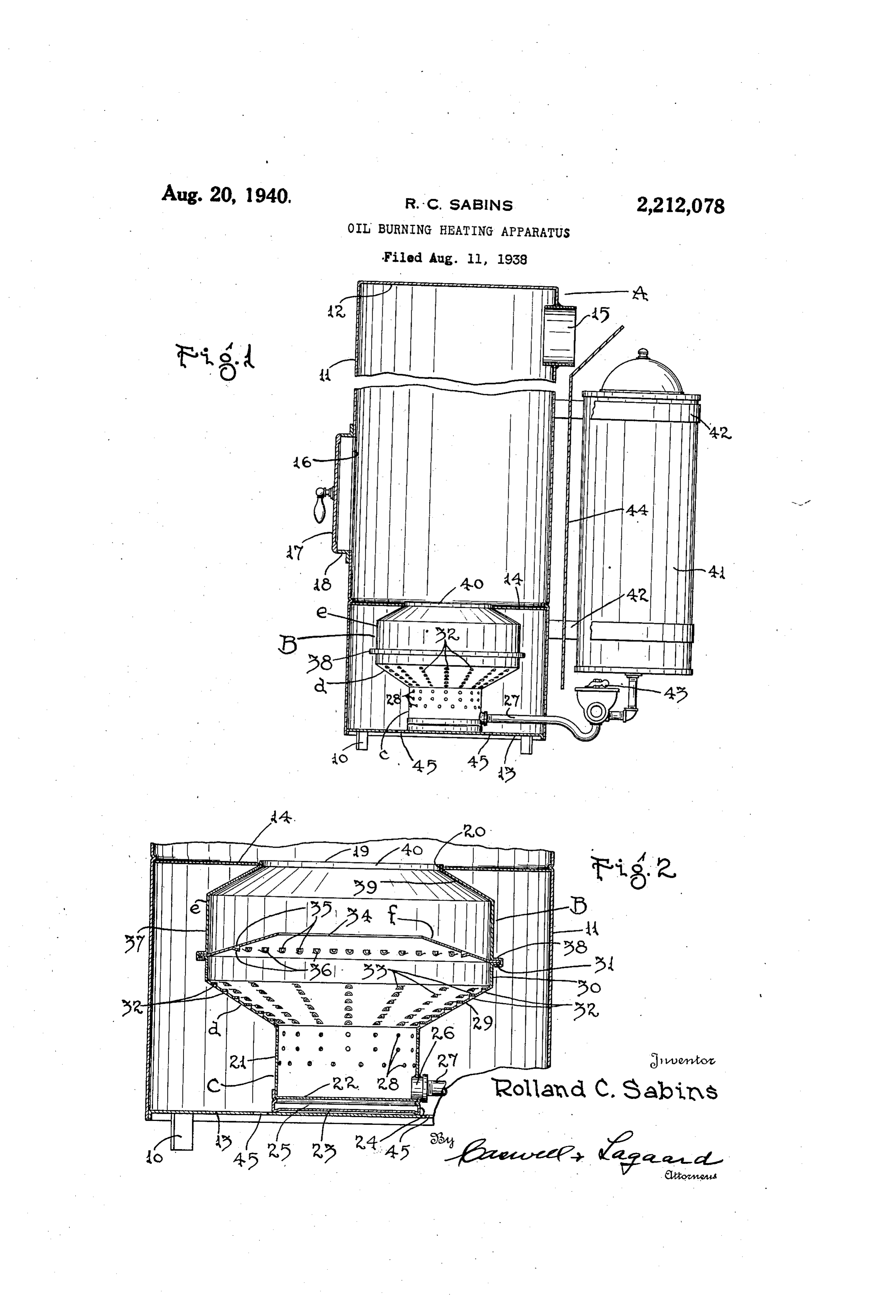
My invention relates to improvements in oil said bottom 3, while the mouth 9 thereof opens. burning heating apparatus and particularly to into the upper portion of the drum through a oil burners, an object thereof being to provide a highly efficient and contrastedly inexpensive central opening 20 in said partition 4. The burner B, preferably formed entirely of 5 5 oil burner of the pot-type which is light in Weight sheet metal, includes a generating well c, body d, and readily adaptable to the various uses to which head e and an internal baffle f. The generating such burnersobject are put. well c consists of an upright cylindrical wall 2, A further of the invention is to provide a bottom proper 22 and a second bottom 23, a burner of the present nature constructed prin spaced from said first bottom through the 10 10 cipally of sheet metal, the parts being designed medium of an annular connecting flange 24, Said so that they may be rapidly and inexpensively bottoms 22 and 23 being spaced apart to provide constructed and likewise assembled to complete a heat insulating air space 25 therebetween for the structure. - the purpose of preventing the dissipation of heat A further object of the invention is to enhance from the inner bottom 22. Near said inner bot- 5 15 the safety of burners of the present type by pro tom 22, the wall 2 of the generating well c is viding a burner in which a minimum quantity of fitted with a coupling 26 to receive a pipe 2 for . accidentally accumulated oil will operate, through introducing fuel oil into said well c. About the the medium of conventional feeding equipment, upper portion of the generating well c, the wall to cut of the supply of oil to the burner. 2f thereof is formed with a multiplicity of air 20 20 Another object of the invention is to provide an openings 28 which admit combustion supporting oil burner of the pot-type designed efficiently to air to said well.
maintain the-burner flames in each stage of a The body d of the burner B is hopper-like in relatively great range of stages.
With the foregoing and other objects in view, . form and includes a wall portion 29 flaring Out wardly and upwardly from the Wall 2 of the gen- 25 25 which will appear in the following description, erating well c, there being in continuation of said the invention resides in the novel combination flaring wall portion 29 an upright cylindrical and arrangement of parts and in the details of wall portion 30 terminating in a horizontally dis construction hereinafter described and claimed. posed annular flange 3. This faring wall por In the drawing, Fig. 1 is mainly a vertical cen tion 29 has a multiplicity of air admitting open- 30 30 trail sectional view of a heating appliance in which ings 32 formed therein. Said openings may con is incorporated an oil burner of the pot-type sist simply of die-formed apertures, but prefer embodying my present invention, said burner ably are produced, as illustrated, by forming being shown in elevation, and Fig. 2 is an enlarged louvers 33 in the flaring wall portion 29. In either fragmentary view of the burner structure shown case, the axes of the openings 32 are directed 35 35 in Fig. 1, the same being illustrated-in vertical horizontally in a radial direction through, the section, centrally
Referring thereof.
to the . in which similar. axis of the burner body d. The annular baffle f drawing surmounts the burner body d, its outer annular reference characters designate similar parts margin resting upon the flange 3 of said body. throughout the several views, it will be observed This baffle f, conical in form, flares upwardly and 40 0 that the illustrated heating appliance includes a inwardly from the burner body d, the opening 34 heating having andrum. A supported upright on legs cylindrical body 0,ff,said drum a top in said baffle being centered axially of the body di 2, . and generating well c. Said baffle f is formed a bottom 3 and a horizontal partition 4 between with a multiplicity of apertures 35 distributed said top and bottom. At the upper portion of the about the same, these apertures, as shown, being 45. 45 drum body if is a flue collar 5 with which a provided by forming louvers 36 in said baffle. The stove pipe (not shown) is attached in the usual heade of the burner B includes a cylindrical wall manner. Beneath this flue collar fs and above portion 37 formed with a horizontal footing flange the horizontal partition 4, the drum body f is . 38 bearing upon the outer marginal portion of the provided with an access opening 6, said open baffle f which is seated upon the horizontal flange 60 50 ing being normally closed by a door f7 hingedly 3f of the body d. This footing flange 38 is mounted on a door frame 8 encompassing said crimped around the bailief and also around the opening 6 and attached to said drum body. flange 3 on the body drigidly to unite said body The pot-like burner of my present invention, d, baffle if and head e in unitary fashion. In up indicated in its entirety by the reference letter B, 55 is shown as disposed between the bottom 3 and ward and inward continuation of said wall por- 65.
Page 3
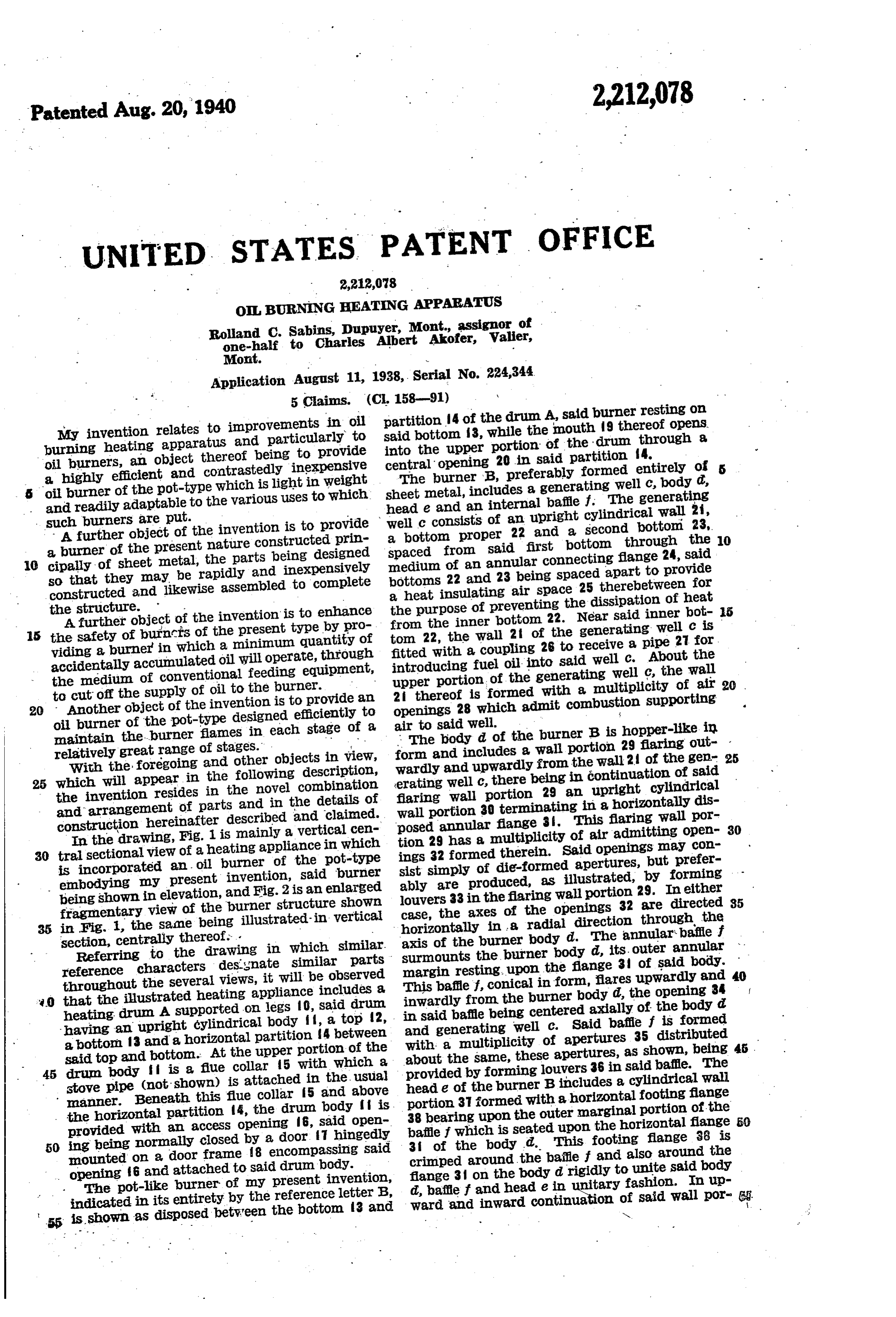
tion 37 of the head e. is a sloping wall portion 39 my improved burner, afford, in a single burner having a short vertical flange 40 forming the structure, mouth 9 of the burner, said mouth and the burners ofthe equivalent of any of a plurality of different capacities capable of eff opening 34 of the baffle f and said generating well c being co-axially disposed. As shown, this short cient operation. r Changes in the specific form of my invention, 5 vertical flange 40 on the burner head e is snugly as herein disclosed, may be made within the received in the burner opening 20 in the part tion 4 of the heating apparatus to which the the scopespirit of what is claimed without departing from of my invention.
O The fuel oil pipe 27 may be connected with Having described my invention, what I claim any suitable source of supply and regulation of as new and desire to protect by Letters Patent is: 10 the flow. of oil therethrough to the generating well 1. In a burner of the pot-type, a generating well c may be effected in any suitable manner portion having air admitting openings in the upper selectively to produce high or low flame or flames thereof, abody flaring outwardly and up
at various intermediate stages. In the draw mittingwardly from said well and formed with air ad ing I have illustrated a fuel supply tank 4 sup differentopenings therein about the same and at elevations, a head in upward continua ported by straps 42 secured to the drum wall tion of said body, said head being flared inwardly. of the heating appliance. The supply pipe 27 and upwardly at its upper portion said head and leading to the generating well c of the burner B 20 is connected with this tank 4 f at the bottom body forming a combustion chamber, said head thereof and in this pipe 27 is fitted a metering having a central opening: therein forming the 20 mouth of the burner, an annular baffle disposed valve 43 of conventional construction for regulat wholly ing the flow of oil into the burner. Interposed upwardlywithin the combustion: chamber flared 25 between the drum wall f and tank 4 and, sup Opening therein for theand and inwardly apertured about the return of gases of high ported by the tank supporting straps 42 is a temperature to the interior of the burner body. 2 guard 44 shielding said tank from the heat radi 2. En a burner of the pot-type, a body flaring
Outwardly and upwardly and formed with
The bottom 3 of the heating drum supplies a louvered footing for the supporting flange 24 of the well c, air admitting openings therein about 30 said bottom 3 having a plurality of openings 45 the same, and at different elevations, a head in therein for admitting air to the burner B. upward continuation of said body said head and 0 In operation, liquid fuel is admitted to the body forming a combustion chamber, said body well c of my burner by opening the metering having a central opening therein forming the 35 valve 43 more or less according to the existing mouth of the burner, an annular baffle disposed heating requirements, such fuel, of course, being wholly within the combustion chamber flared upwardly and inwardly and provided with ignited to start the initial generation of gases louvered openings therein for the return of gases to be burned. This generation of gases initially. of high temperature to the interior of the burner and in the continued Operation of the burner is body, the axes of said louvered openings in said enhanced by reason of the relatively small diam-.
eter of the well c into which the liquid fuel is body and baffle extending substantially hori- . . Zontally in radial disposition with respect to the 40 admitted and by reason of the heat insulated Wertical bottom of the well structure which retains the 3. In aaxis of the burner structure. pot-type burner, a vaporizing well hav heat in such structure for generating purposes. ing air admitting openings about the same in the Employing a conventional metering valve having upper portion thereof, a body a number of settings ranging from a minimum and upwardly from said well andflaring outwardly formed with air 45 low setting to a maximum high setting, the feed admitting openings therein at different eleva ing of liquid fuel into the well c of the burner is regulated to produce flames of varying sizes. At tions about the same, ahead in continuation of the low setting of the metering valve 43, a flame said body having a central mouth forming open ing therein, an annular baffle within the burner of minimum size is produced, the same burning structure in the region of the mouth of said Well C and re in, inwardly and upwardly inclined there- 50 ceiving its combustion supporting air from the ingssaid baffle being formed with marginal open about the same for returning gases of high openings 28 in the wall 2 f of said well. As the settings of the metering valve 43 are advanced, temperature to the from the interior of the burner head interior of the burner body, and means the burner flames are correspondingly increased in size, the outward flaring of the louvered burner for introducing fuel oil into the well of the 55 burner, said well, body and head having a com body d affording proportionately increasing mon vertical axis, said air admitting openings in diametrical capacity for said flames as they grow said proportionately larger upon advancing the meter baffle body and the marginal openings in said being arranged to direct the passageway .
ing valve setting. At all stages of the burner therethrough respectively, of air and gases sub- 60 flame, the louvered baffle f functions to return stantially horizontally in radial directions rela heated gases, burned and/or unburned, from the tive to said common vertical axis. outer annular portion of the space within the 4. In a burner of the pot-type, a generating burner heade to the interior of the burner body d with the result that the efficient burning of the well, an annular wall extending outwardly from said well and formed with air admitting openings 65 gases beneath the baffle f is insured and with the therein, further result that the flame characteristics at . upwardlyafromcylindrical wall structure extending said annular Wall, a second an all settings of the metering valve 43 remain sub nular wall extending inwardly from the upper stantially constant. In other words, the fuel 70 gases are completely burned in the flames, which, most portion of Said cylindrical wall structure and having a central opening thereinforming the 70 though of different sizes, have substantially the mouth of the burner, and an annular baffle with same color and substantially the same patterns in the burner symmetrically shaped relative to the axis of the disposed intermediate the first and burner. Second named annular walls and extending in Wardly from the cylindrical wall structure, said
The herein indicated advantages residing in cylindrical wall being imperforate above said is
Page 4
ture and having a central opening therein form baffle, the central opening in said baffle being con-. ing the mouth of the burner, and an annular centric with the mouth of the burner, said baffle baffle within the burner disposed intermediate having return openings therein intermediate the the first and second named annular Walls and central opening and the cylindrical wall struc flaring inwardly and upwardly from the cylin 5 ture, said return opening being beneath said drical wall structure, the central opening in said second annular wall outside of the vertical con baffle being concentric with the mouth of the fines of the mouth-forming opening therein. burner and having return openings therein inter 5. In a burner of the pot-type, a generating mediate the central opening and the cylindrical well having air admitting Openings in the upper wall structure, said return openings extending in 10 portion thereof, an annular wall flaring out a substantially horizontal direction and being i) wardly and upwardly from said well and formed disposed beneath said second annular wall out with air admitting openings therein, an im side of the vertical confines of the mouth-form perforate cylindrical wall structure extending up ing opening therein. ROLAND C. SABINS.w wardly from said flaring wall, a Second annular wall flaring inwardly and upwardly from the uppermost portion of said cylindrical wall struc
Provenance
- Collection
- Cited prior art
- Original PDF
- patentimages.storage.googleapis.com →
- Filed
- 1938-08-11
- Pages
- 4
- Method
- pdftotext (the PDF's own text layer) + pdftoppm 300dpi page scans
- Source
- Google Patents bibliographic record
- Granted
- 1940-08-20
- Inventors
- Rolland C Sabins; CHARLES ALBERT AKOFER
- Transcribed from
- patentimages.storage.googleapis.com →