patent · US4312709A
Solar energy collection still
26 January 1982
Page 1 — bibliographic record
United States Patent (19) 11) 4,312,709 Stark et al. 45 Jan. 26, 1982 54). SOLAR ENERGY COLLECTION STILL 3,330,740 7/1967 Duffy .................................. 202A234
75) Inventors: Virgil Stark, New York, N.Y.; 3,428,529 2/1969 Gumucio .............................. 2O3/10 Alexandre Wayda, Lausanne, 3,738,734 6/1973 Tait et al. .. ... 350/79 Switzerland; Paul Rousset, Cannes, 3,915, 147 10/1975 Rineer ... ... 26/440 France 3,965,683 6/1976 Dix ............ ... 350/179 3,970,070 7/1976 Meyer et al...... ... 126/440 73) Assignee: North American Utility Construction 3,991,741 11/1976 Nothrup et al. . ... 350/21 Corp., New York, N.Y. 4,01,857 3/1977 Rice .............. ..., 26/440 4,022,186 5/1977 Northrup. ... 350/21 21 Appl. No.: 866,067 4,057,048 1/1977 Maine .................................. 26/440
22 Filed: Dec. 30, 1977 4,081,289 3/1978 Campbell .............................. 136/89
Related U.S. Application Data FOREIGN PATENT DOCUMENTS 62) Division of Ser. No. 746,065, Nov. 30, 1976, Pat. No. 12800 of 0000 Japan .
30 Foreign Application Priority Data 51-2043 of 1976 Japan. Jul. 9, 1976 FR) France ................................ 76. 20986 Primary Examiner-Wilbur L. Bascomb, Jr. Oct. 8, 1976 FR France ................................ 76 30248 Attorney, Agent, or Firm-Kenyon & Kenyon 51). Int. Cl. ................................................ CO2F /14 (57) ABSTRACT 52 U.S. C. ...................................... 202/83; 202/172; Apparatus and methods for concentrating and collect 202/181; 202/202; 202/234; 203/10; 203/100; ing solar energy are disclosed. In accordance with the 203/DIG. l; 126/435; 126/440; 350/418 invention, solar energy is concentrated by economical 58) Field of Search .................. 126/440, 435; 203/10, refringent lenses or lens systems including fluid lenses 203/11, 1, 100, DIG. 1, DIG. 17, 22, 25; and/or Fresnel-type lenses. The lenses concentrate the 202/234, 180, 177, 181,202, 172-174,83; 159/1 solar energy preferably along lines in continuous linear S, 1 SF; 350/179, 211 foci or in discrete foci at an elongated collector con (56) References Cited prising one or more fluid-carrying conduits and one or
photoelectric cells are located in or on the collector
along the linear foci or at the discrete foci and operate 1,599,48 9/1926 Marcuse ... ... 126/440 at increased efficiency with heat being removed by the l,683,266 9/1928 Shipman .............................. 26/440 collector. A first fluid in the collector is heated by the 1,704,173 3/1929 Chesney . concentrated solar energy and in a preferred embodi 1,951,403 3/1934 Goddard ............................. 26/440 ment is used to heat a second fluid contiguous to the 2,445,350 7/1948 Ginnings ...................... 2030G. first fluid, the first fluid having a boiling point exceeding 2,636,129 4/1953 Agnew ..... ... 203DG, 1 that of the second fluid. In a preferred embodiment, the 2,788,316 4/1957 Bjorksten...................... 203/DIG. first fluid is carried in an inner conduit while the second 3,088,882 5/1963 Justice ................................. 202/234 fluid is carried by an outer conduit which encloses the 3,104,210 9/1963 Mount .. . 203DG. inner conduit and first fluid. Thus, the two fluids can be 3, 159,554 12/1964 Mount ................................. 202/234 heated to different temperatures by a single concentrat 3, 190,816 6/1965 Ademac ... ... 202/234 3, 192,133 6/1965 Adenac .... ... 202/234 ing system and used for different purposes. Addition 3,314,862 4/1967 Hay ....... ... 202/234 ally, the invention provides for the storage of energy 3,317,406 5/1967 Beard .................................. 202/18O using two fluids of different boiling points. Also dis
Page 2
closed are methods and fixed and portable apparatus for ent invention provides heat from solar energy at a cost distilling water containing salt or other substances by competitive with heat produced from fuels. evaporation of the water and condensation of the water vapor wherein preferably the heat of condensation is recovered. The invention also provides for assemblies of individual systems to form larger systems. The pres 15 Claims, 31 Drawing Figures

Page 3
Drawing sheet — no readable text.
Page 4
Drawing sheet — no readable text.
Page 5
Drawing sheet — no readable text.
Page 6
Drawing sheet — no readable text.
Page 7
Drawing sheet — no readable text.
Page 8
Drawing sheet — no readable text.
Page 9
Drawing sheet — no readable text.
Page 10
Drawing sheet — no readable text.
Page 11
Drawing sheet — no readable text.
Page 12
Drawing sheet — no readable text.
Page 13
Drawing sheet — no readable text.
Page 14
However, the efficiency of these panel systems is low,
SOLAR ENERGY COLLECTION STILL from about 30% to about 60%, and they require large spaces resulting in large heat losses, and they also re
This is a division of application Ser. No. 746,065, filed quire a high capital investment. The use of Fresnel-type Nov. 30, 1976 on which U.S. Pat. No. 4,134,393 issued lenses and fluid lenses is known in the art for focusing on Jan. 16, 1979. solar energy. See, for example, U.S. Pat. Nos. 3,915, 148;
BACKGROUND OF THE INVENTION 1,081,098; Japanese Pat. No. 28-2130, and Australian 1. Field of the Invention Pat. No. 131,069. However, none of the known systems The present invention relates to methods and appara O is capable of converting and storing solar energy effi tus for concentrating and collecting solar energy for ciently and none can produce heat at an economical many uses including the conversion thereof to heat capital investment such that the use of solar energy is energy and/or electrical energy to be used for many competitive with other energies. The prior art also does purposes. The present invention also relates to the stor not disclose obtaining temperatures in the order of a few age and use of heat energy during hours without sun or 5 hundred degrees C. while also obtaining at the same with reduced sun. The present invention further relates time lower temperatures usable for home heating and to the treatment of water containing salt and/or other water heating or other purposes. Nor is there in the substances using fixed and portable apparatus and meth prior art a system which is capable of storing heat en ods according to the invention. More particularly, the ergy from solar energy during periods of interrupted invention relates to methods and apparatus using fluid solar energy for any length of time and which also is and/or Fresnel concentrating lenses and lens systems capable of providing different temperatures simulta and elongated collectors comprising at least one fluid neously and also utilizing the luminous and infrared rays carrying conduit located at the foci of the lenses. of the sun. With respect to electrical generation, it is 2. Description of the Prior Art known that concentrating the solar energy at a photoe The energy emitted by the sun corresponds to a high 25 lectric cell will increase the electrical output of cell; temperature in the order of 6000 C., and is emitted in however, there is the disadvantage that the increased the form of radiation which arrives at the earth with a heat in the photoelectric cell resulting from the concen wavelength distribution comprising about 3% ultravio tration will also limit the cell output, Known photovol let rays, 42% visible light rays, and about 55% infrared taic devices produce a maximum of about one watt per rays. It is well known that surfaces exposed to the sun 30 hour per cell. Assuming a cost of $10 per photovoltaic collect at least to some degree the solar radiation and cell, a system using non-concentrated solar energy to that the absorption of this radiation results in a heating generate about 1 kilowatt per hour requires a capital of the material constituting the surface. It is also known cost of at least $10,000 which is not competitive for that electricity can be produced by photoelectric de normal uses. With respect to solar stills, known stills vices exposed to the sun's rays. 35 used for distillation of seawater have low efficiencies There have been many attempts in the past to collect and the cost of heating the water is high as the least and utilize pollution-free and essentially nonconsumable amount of heat required to vaporize the water is not solar energy to meet many energy needs. Much atten recovered from the condensation but rather is lost. tion has been directed to the conversion and utilization In accordance with the invention the prior art draw of solar energy in the past few years because of the 40 backs and disadvantages are substantially overcome and realization that fossil fuels are exhaustable and that a additional advantages realized. burning of these fuels produces pollution. Solar energy, SUMMARY OF THE INVENTION on the other hand, is inexhaustable and available above the clouds at an average energy level of approximately The present invention is embodied in and carried out 1350 watts per horizontal square meter. A percentage of 45 by methods and apparatus for concentrating, collecting, this energy, depending on atmospheric and weather storing and utilizing solar energy. In accordance with conditions, dust, pollution, etc., is available at the sur the invention, refringent lens means concentrate the face of the earth during periods of sunshine which vary solar energy along a length at elongated collector up to about 4000 hours per year depending on location. means containing at least one fluid therein. Further in Even more recently, the shortage of fossil fuels particu 50 accordance with the invention, the lens means comprise larly oil and the high cost thereof have sparked new economical fluid or Fresnel-type lenses and lens systems attempts to harness the energy of the sun. As in the past, which focus the solar energy substantially along the however, fuels are still a lesser expensive source of length at the collector means along substantially contin energy and the same problems of high capital cost and uous lines or in lines of substantially discrete points. the cyclic nature of the sun requiring storage capability 55 Thus, the at least one fluid in the elongated collector have still not been satisfactorily solved. For example, may be efficiently heated to high temperatures in the refringent lens focusing systems, most using reflecting order of a few hundred degrees C. The fluid lenses are collectors and most including sun-tracking systems, advantageously made from separate upper and lower have heretofore been used but are uneconomical and solar energy transmitting plates which are installed in impractical because of the high cost involved. A con 60 frame means in a fluid-tight manner, or the fluid lenses ventional way for obtaining lower temperatures up to may be welded, extruded, or blown similar to glass or about 80 C. consists of using dark-colored panels plastic bottles. The fluid within the lenses preferably has which absorb the solar radiation, and combining these an index of refraction similar to that of lens plates. The panels with means circulating a heat-carrying fluid in a enclosure in the lens containing the fluid is advanta heat-exchanging manner with the panels. It is also 65 geously communicated with the collector means to known to improve the efficiency of these systerns by enhance performance. Still further in accordance with placing one or more glass plates above the panels to the invention, the elongated collector means comprises produce a greenhouse effect for reducing heat losses. a plurality of fluids, adjacent ones of which are contigu
Page 15
ous. The fluids are preferably isolated and disposed in means to advantageously utilize the latent heat released adjacent conduits and the fluids preferably differ and by the vapor condensing on said smooth surface and have varying boiling points. The theoretical focus or transferred to the water to be distilled. The heat re foci of the lens means are preferably on the surface of or leased by the condensing water is thus not lost and within the higher or highest boiling point liquid. In a returned to the system by means of the lens fluid and the preferred embodiment, the elongated collector means circulation thereof, thereby increasing substantially the comprises at least two conduits; one of the conduits efficiency of the system and the quantity of heated containing a first fluid having a first boiling point is water obtained from water to be distilled. Salt may be located within a second conduit containing a second produced from the resulting concentrated brine and fluid having a second boiling point. Preferably, the solar O credit obtained from the sale thereof to lower the over energy is concentrated at the inner liquid which has a all cost of obtaining distilled water. According to one boiling point which exceeds that of the outer liquid. The embodiment of the invention, the still is portable and is conduits and fluids are solar energy transmitting or easily assembled and disassembled. Advantageously, opaque or darkened depending on the location of the the stills are operative to distill seawater and brackish lens means focus. By solar energy transmitting it is 5 water and may be used at sea, for example, on life boats, meant that the solar rays are substantially transmitted and in desert areas.
through the material as opposed to being absorbed and The collecting surface area of the apparatus of the with respect to the luminous rays of the sun is synony present invention is much smaller than the collecting mous with the word transparent. In this way, the fluid surface area of flat panel systems and is from about 2% may be heated to different temperatures and accord 20 to about 10% of the surface area of flat panel systems ingly can be utilized for different purposes, if desired. for comparable energy collection. Lower collecting Regulation of the fluid flow rates and selection of con surface areas result in lower heat losses, higher efficien duit sizes and shapes assists in providing different tem cies, lower cost for energy produced, and require lower peratures which may be utilized for different purposes. investment cost. The apparatus may be enclosed ac Arrangement of multiple conduits carrying multiple 25 cording to the invention to further reduce heat losses fluids in accordance with the invention can provide and form enclosed systems. Since the temperature of the energy for many different uses including a vapor and fluid can be raised to a relatively high value in the pres super-heated vapor for mechanical devices including ent invention, a variety of simultaneous uses are avail turbines. Advantageously, the lower boiling point fluid able including using a plurality of fluids of different has a low latent heat of vaporization and is useful for 30 boiling points for many different purposes. The higher this purpose. Additionally, heat is stored in the higher temperatures attainable and the use of multiple fluids boiling point fluid by permitting its temperature to rise permit heat storage during non-solar energy periods. during periods of solar energy to a temperature substan The higher temperatures permits the use of smaller tially higher than that of the lower boiling point fluid storage tanks or other storage means. For example, for which may be used as a working fluid. Heat is removed 35 the same fluid, 2 times less space is required to store the from the higher boiling temperature fluid by, for exam same heat at 200" C. than at 80° C. The higher boiling ple, circulating the lower boiling point fluid past the point fluids and the heat storage capability obviate the higher boiling point fluid. The invention also provides need for antifreeze. According to the invention, diffuse for the union of individual systems to form larger com solar energy representing up to about 40% of the solar posite systems. Thus, a high degree of concentration of 40 energy received is concentrated at the collector means solar energy is possible. Still further in accordance with and thereby utilized which is not the case with reflect the invention, both the infrared and luminous rays of the ing concentrators. The efficiency of apparatus accord sun may be simultaneously utilized. Photoelectric cells ing to the invention is high and its cost is low in compar can be disposed at the collector means such that the ison to known systems and the cost of obtaining energy luminous rays are concentrated thereat for maximum 45 competitive with fuels. Moreover, the present invention electrical energy production while the heat generated has the advantage of generating electricity, producing by the concentration of the infrared rays is removed by heat simultaneously or separately and storing heat and is one or more fluids in the collector means whose flow useful in many applications, thus increasing system effi rates and volumes may be regulated. Thus, in accor ciency, utilization and amortizing the cost of the system. dance with the invention, the solar energy is concen 50 Since reflective surfaces which do not reflect diffuse trated by a factor in the order of up to 50 to 100 so that solar energy are not required to practice the present one of the known cells is able to produce up to 50 to 100 invention, the need to maintain reflective surfaces watts per hour instead of 1 watt per hour during periods which weather easily and frequently require refurbish of sunshine. Further in accordance with the present ing is obviated. Also, as will be more apparent hereinaf invention, water may be distilled by locating the collec 55 ter, tracking equipment is not essential to practicing the tor means in the water to be distilled, above which is present invention, particularly tracking equipment of positioned lens means and a downwardly sloping sub the type which follows the sun on a daily basis as the stantially smooth, preferably planar surface, whereby system is located east-west. Apparatus according to the water is evaporated and condenses on the smooth sur invention can advantageously be combined with a con face which carries the condensed water to a collecting ventional heat pump producing and storing additional vessel positioned below the lower side thereof. Means heat from the surrounding air or water. This rinay be are provided to completely enclose the apparatus while particularly significant during winter months when permitting movement of the lens or the entire system to lower sun energy is available and there is more con track the sun seasonally or daily. It is preferred that the sumption of energy for heating. lens system for the water distilling apparatus comprise 65 These and other aspects of the present invention will fluid lens means which include said smooth surface and be more apparent from the following description of the in which the solar energy transmitting fluid forming preferred embodiments thereof when considered with part of the lens means is circulated within the collector the accompanying drawings.
Page 16
BRIEF DESCRIPTION OF THE DRAWINGS FIG. 15 is a schematic perspective diagram of a com posite system according to the invention for distilling
The present invention is illustrated by way of exam water comprising individual systems each comprising ple and not limitation in the figures of the accompany two elongated fluid lenses and a collector located in the ing drawings in which like numerals refer to like parts water to be distilled comprising two fluid-carrying con and in which:
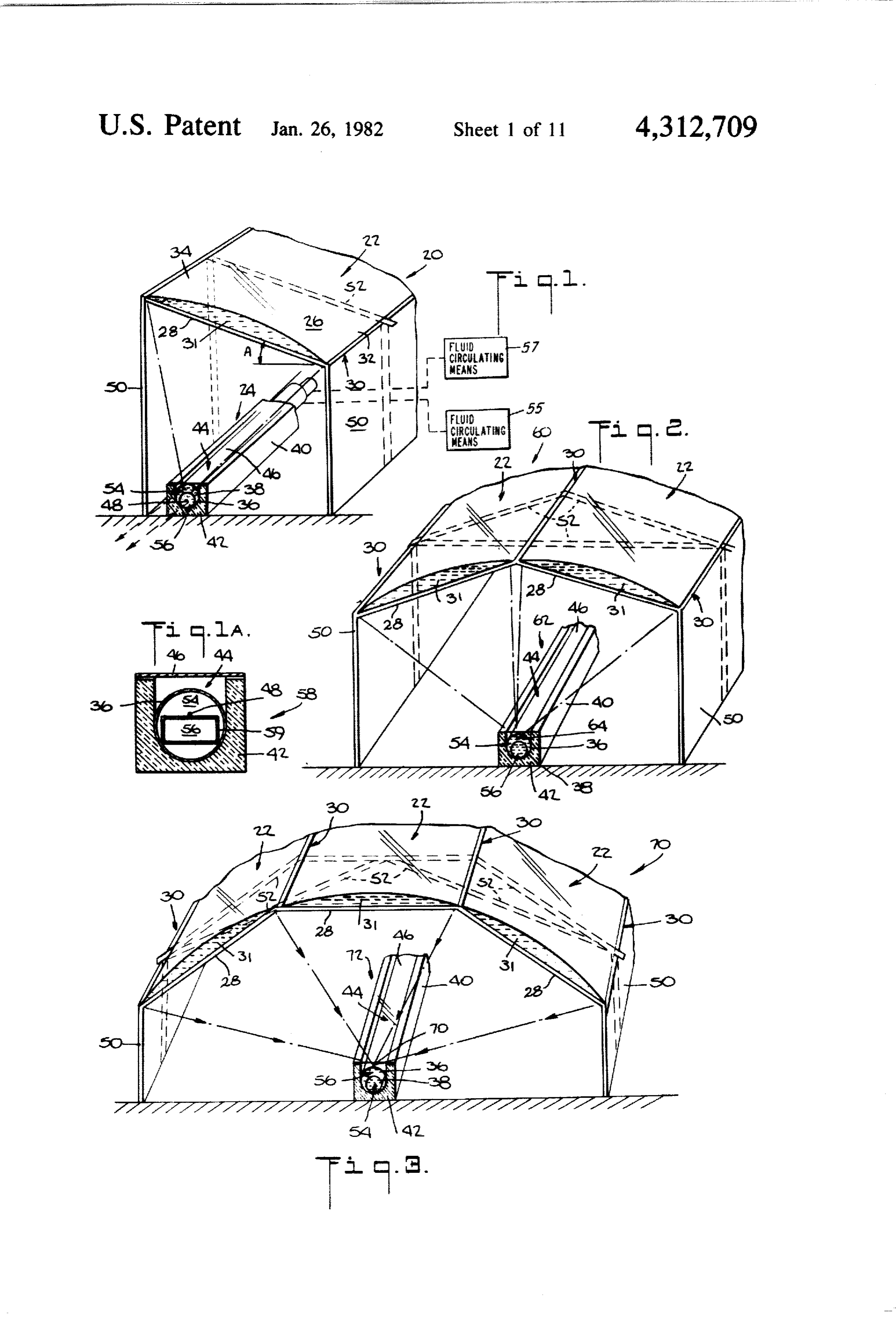
FIG. 1 is a schematic perspective diagram showing a duits, one enclosed in the other;
FIG. 16 is a schematic perspective diagram of an system according to the invention comprising an elon other composite system according to the invention for gated fluid lens and a collector comprising two fluid distilling water similar to that of FIG. 15 in which the carrying conduits, one enclosed in the other with the 10 collector comprises a single fluid-carrying conduit and focus of the lens located within the inner conduit; lenses concentrating the solar energy in a single linear FIG. 1A is a cross-section view of another embodi ment of the collector of FIG. 1 showing a rectangular focus;
inner conduit on the upper surface of which is located otherFIG. 17 is a schematic perspective diagram of an the focus of the lens of FIG. 1; s system according to the invention for distilling FIG. 2 is a schematic perspective diagram showing water comprising a single elongated fluid lens and a another system according to the invention similar to collector comprising a single fluid-carrying conduit; that of FIG. 1 comprising two radially juxtaposed, elon FIG. 18 is a schematic cross-section diagram of a gated fluid lenses in which the focus thereof is located composite system according to the invention for distill within the outer conduit; ing water comprising individual systems, each compris FIG. 3 is a schematic perspective diagram showing ing a single, elongated, movable fluid lens to follow the still another system similar to those of FIGS. 1 and 2 seasonal location of the sun and a collector comprising according to the invention comprising three radially a single fluid-carrying conduit in which the individual juxtaposed, elongated fluid lenses in which the focus systems are enclosed;
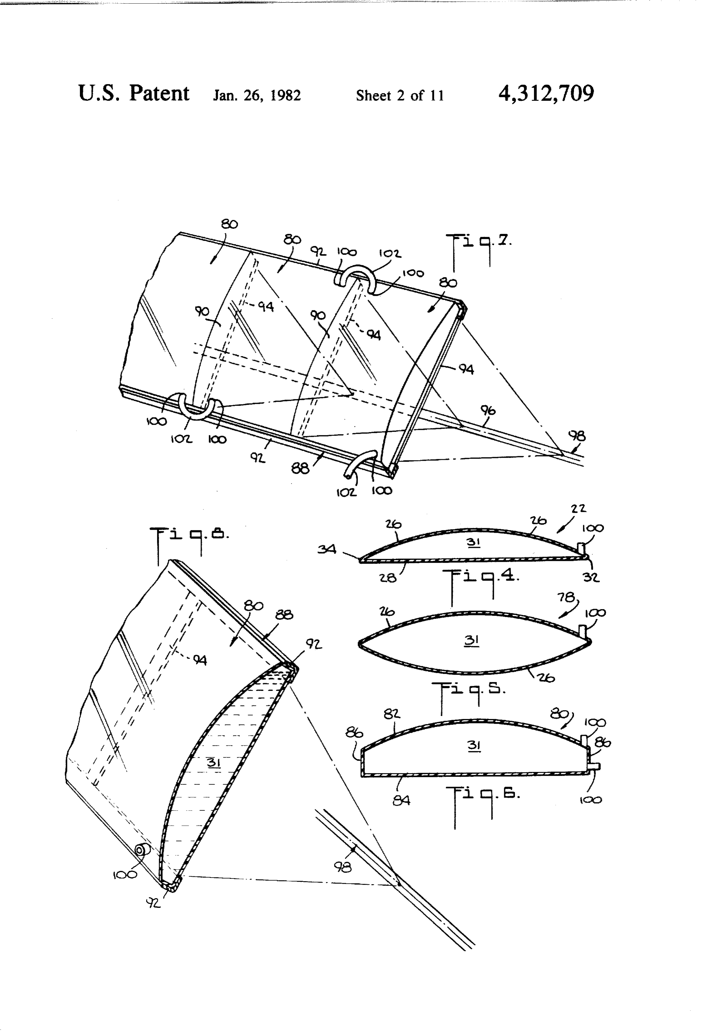
thereof is located on the upper surface of the outer 25 FIG. 19 is a transverse cross-section view of another conduit; - enclosed system according to the invention for distilling FIGS. 4-6 are cross-section views showing different water also comprising a single, elongated, movable lens configurations of fluid lenses according to the inven and a collector comprising a single fluid-carrying con
FIG. 7 is a perspective view showing a series of lon 30 duit;
gitudinally juxtaposed fluid lenses and means for inter of FIG, the 20 is a perspective view partly in cross-section system of FIG. 19;
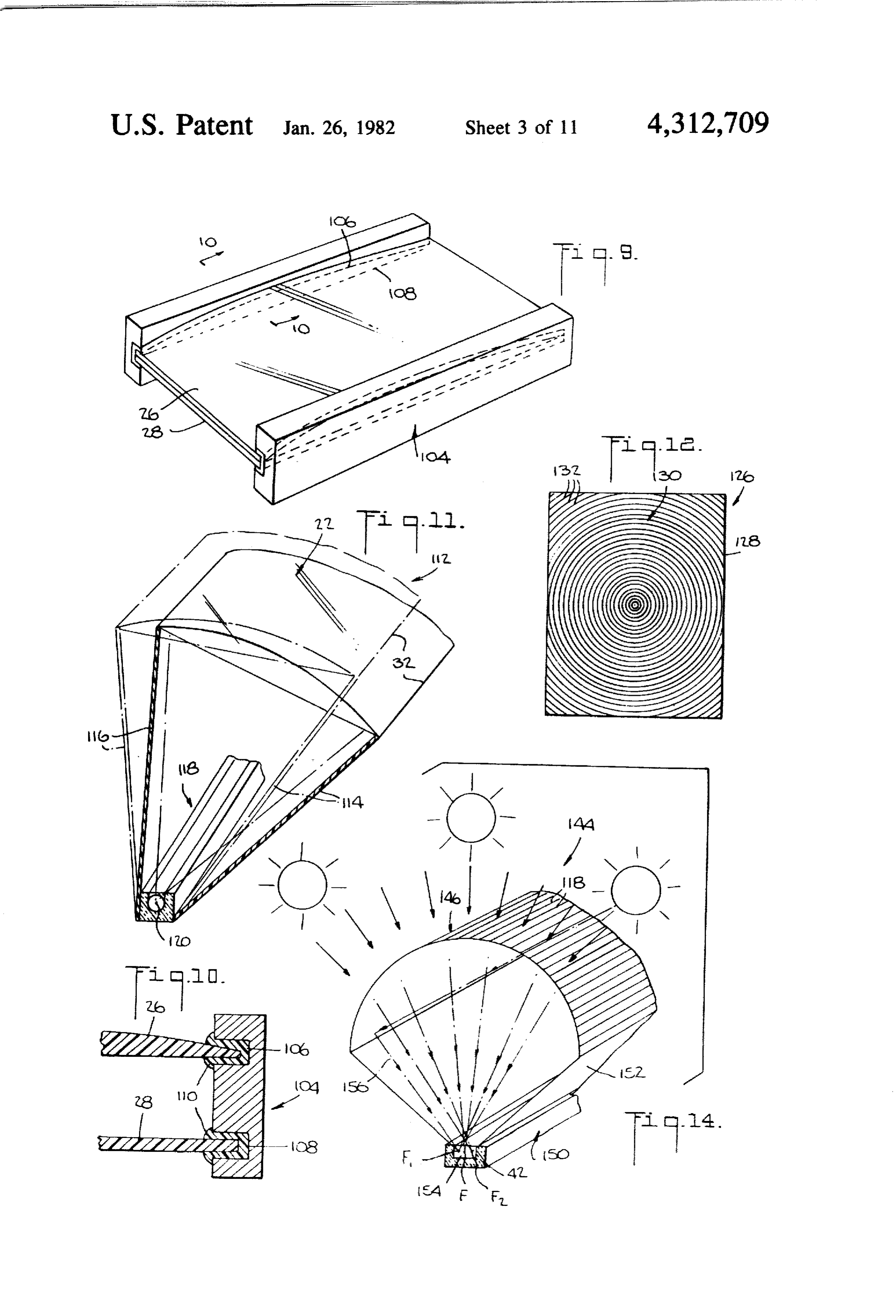
communicating the enclosures of the respective lenses, FIG, 21 is a transverse cross-section view of another this arrangement being utilizable to arrange a plurality of longitudinally juxtaposed lenses where single lens are enclosed system according to the invention for distilling now shown; - 35 water also comprising a single, elongated, movable lens FIG. 8 is a detail perspective of FIG. 7 showing the and a collector comprising a single fluid-carrying con lens frame; duit, and having two sliding side panels which form FIG. 9 is a perspective view of a lens system accord bags for collecting the condensate; ing to the invention comprising two separate plates for FIG. 22 is a transverse cross-section view of still enclosing a lens fluid and a frame for sealing the plates 40 another system according to the invention for distilling into a fluid-tight lens; water comprising a single, movable, elongated, planar FIG. 10 is a cross-section view of the lens and frame Fresnel-type lens having a linear focus and a collector of FIG. 9 taken along line 10-10; comprising a single fluid-carrying conduit; FIG. 11 is a schematic perspective diagram similar to FIG. 23 is a schematic perspective diagram of a por that of FIG. 1 showing another system according to the 45 table, easily assembled and disassembled system having invention in which the system is enclosed, the single a fluid lens for distilling water according to the inven lens is movable to follow the seasonal location of the tion; - sun and in which the collector comprises a single fluid FIG. 24 is a schematic perspective diagram of an carrying conduit; other portable easily assembled and disassembled sys FIG, 12 is a plan view of a planar, point-focusing, 50 ten having Fresnel lenses for distilling water according Fresnel-type lens;
FIG. 13 is a schematic perspective diagram showing to the invention;
another system according to the invention comprising another FIG. 25 is a schematic perspective diagram of still portable system having fluid lenses for distilling an elongated, planar Fresnel-type lens having a linear water according focus and a collector comprising three fluid-carrying 55 FIGS.26 and 27toare the invention; plan side and front views, respec conduits in which an outer conduit encloses two inner conduits and in which the focus of the lens is located tively, of another system for distilling water according within the outer conduit; : to the invention showing means for adjusting the incli FIG. 13A is a cross-section view of part of another nation of the fluid lens and for adjusting the horizontal collector comprising three fluid-carrying conduits in orientation of the entire system;
which the innermost conduit is enclosed by the interme FIG. 28 is a cross-section view of a photoelectric cell diate conduit which is enclosed by the outermost con positioned in a fluid-carrying conduit to produce elec duit; tricity from solar energy according to the invention FIG. 14 is a schematic perspective diagram showing with fluid circulating inside and/or outside the conduit yet another system according to the invention compris 65 to remove heat; and ing an elongated curvilinear Fresnel-type lens and a FIG. 29 is a perspective view of a collector according collector comprising a single rectangular fluid-carrying to the invention comprising apertures for collecting conduit; solar energy from point focus lenses.
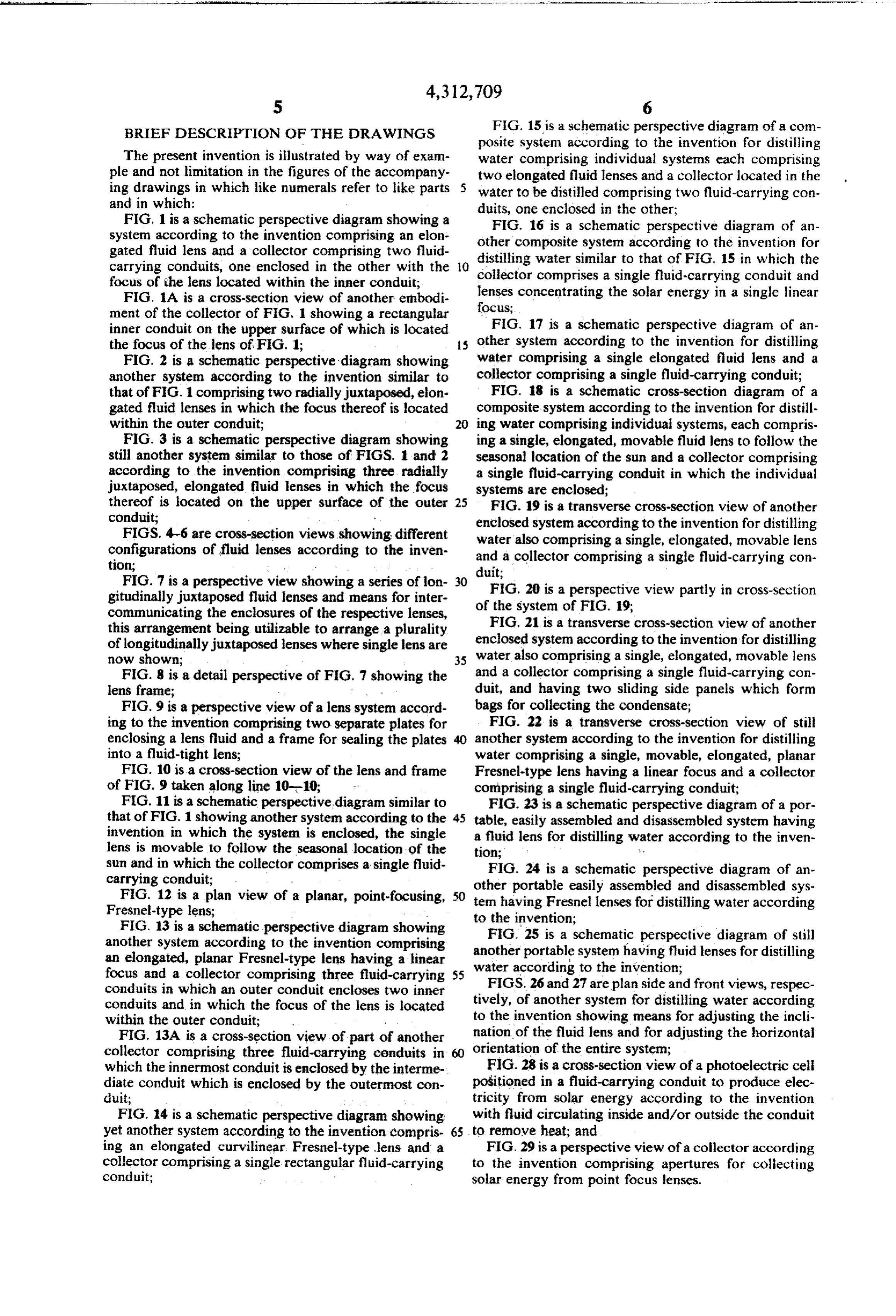
Page 17
DESCRIPTION OF THE PREFERRED temperature attained depending on many factors such EMBODIMENTS as the flow rate of fluids 54, 56, the diameters of con duits 36, 38 sun intensity and position, insulation, heat
In FIGS. 1-3 are shown solar energy collecting sys exchange rates, etc. Fluid circulating means 55, 57 are tems according to the invention comprising refringent provided to control the circulation of fluids 54,56 fluid lens concentrators and fluid-containing solar en through conduits 36, 38 respectively. Fluid 54 is se ergy collectors. Referring to FIG. 1, system 20 is shown lected to have a boiling point which is less than the comprising an elongated fluid lens concentrator 22 and boiling point of fluid 56, preferably at least 50 C. less collector 24 in the form of elongated fluid-containing than the boiling point of fluid 56, and preferably in the conduits. Elongated fluid lens 22 comprises solar en O temperature range of from about - 62 C. to about 100 ergy transmitting plates 26, 28 mounted in frame 30 and C. Such a fluid is suitably water. It is also preferred that spaced to enclose solar energy transmitting fluid 31. In fluid 54 have a low latent heat of vaporization, for ex the emobodiment shown in FIG. 1, upper lens plate 26 ample, from about 20 calories per kilogram to about 270 is convex and lower plate 28 is planar. The respective calories per kilogram, and such fluids may comprise by sides 32, 34 of lens plates 26, 28 and the ends of the lens 15 way of example and not limitation freon, butane, pro plates (not shown in FIG. 1) are sealed to be fluid-tight pane, ammonia, ethyl ether, methyl alcohol, etc. in manners which will be described hereinafter. Alter In operation, solar energy is concentrated in fluid 56 natively, means not shown in FIG. 1 for adding and (lubricating oil) within conduit 38 and raises the temper removing or circulating fluid 31 and air are provided in ature of the oil to about 200 C. Since the focus to lens the sides and/or ends of the lens plates. Additionally, 20 22 is theoretically linear, fluid 56 will be continually means also not shown in FIG. 1 for longitudinally and heated as it traverses the linear focus. Fluid 54 (water) transversely (radially) juxtaposing lenses may be pro which surrounds the oil and conduit 38 is heated pri vided and will also be described hereinafter. In the marily by the oil primarily through conduction. Both embodiment shown in FIG. 1, collector 24 comprises an fluids, oil and water, are circulated by fluid circulating outer elongated conduit 36 enclosing an inner elongated 25 means 55, 57 at predetermined rates to obtain desired conduit 38, both shown to be tubular in shape. Conduit temperatures and may be used for different heat applica 36 is placed in insulating container 40 and is surrounded tions. For example, the water may be heated to about by insulating material 42 except for a longitudinally 70 C-80' C. or more and used for space and hot water extending opening 44 located above conduit 36. Open heating. The water may be heated to lower tempera ing 44 is closed off by solar energy transmitting and heat 30 tures and used, for example, in swimming pools. The insulating plate 46. Plate 46 is suitably made of glass or higher temperature oil may be used for applications plastic and the insulating material 42 is suitably a foam requiring higher temperatures including industrial ap such as polyethylene foam. Collector 24 is located plications or may be used merely to heat the water. below lens 22 and the theoretical linear focus 48 is lo Since the temperature of fluid 56 increases as it tra cated at or along the collector for substantially all of the 35 verses the lens focus, fluids at many different tempera daylight hours. The space between the lens and collec tures are realizable by providing taps for fluid outlet tor is enclosed by side panels 50 which if rigid can also and/or inlet at different points along the focus. Fluid 54 serve to support lens 22 and frame 30 in cooperation may be evaporated and the vapor or superheated vapor with support member 52. For optimum concentration of used to produce mechanical power in a turbine or en solar energy at collector 24, lens 22 is oriented at a 40 gine which, in turn, may generate electricity. Prefera preselected angle A with the horizontal, the longitudi bly, a closed system (not shown) is employed in which nal axis of the lens (and of the system) is oriented along the condensed fluid is returned to collector 24. In such the east-west direction and the convex upper lens plate applications, fluids such as freon, butane, propane, ethyl 26 is oriented to face south (northern hemisphere). The ether, methyl alcohol, ammonia and the like may consti optimum value for angle A depends upon the location 45 tute fluid S4.
of the system 20, and for a fixed system is chosen to give As mentioned hereinbefore, a serious drawback of optimum concentration on a seasonal basis. For mov solar energy systems in general and known systems in able systems, which will be described hereinafter, angle particular relates to the storage of energy during peri A is selected for optimum seasonal solar energy concen ods in which there is no sunshine or the intensity thereof tration or for optimum concentration for even shorter 50 is low, as for example during the night or during periods periods of time. of cloudy weather. In accordance with the present As mentioned hereinbefore, the collector 24 is lo invention, heat is stored for use in those periods in fluid cated at the theoretical focus 48 of the lens 22 and in the 56 which is heated during normal system operation to a embodiment of FIG. 1, conduits 36 and 38 are solar temperature which is at least about 50 C. higher than energy transmitting, the theoretical focus 48 being lo 55 the temperature of fluid 54. Therefore, even when fluid cated within the inner conduit 38. Conduits 36 and 38 56 is not being heated by solar energy or being heated at contain heat-carrying fluids 54 and 56, respectively. a reduced rate, it stores heat and will continue to supply Since the concentration of the solar energy will be heat to fluid 54 due to the temperature difference be greatest in the fluid within the conduit at which the lens tween the two fluids. Preferably, the circulation of fluid theoretical focus is located, i.e., in fluid 56 within con 56 is stopped by fluid circulating means 57 for those duit 38, fluid 56 may be heated to a relatively high periods. Fluid 56 continues to transfer heat to fluid 54 temperature and is therefore chosen to have a relatively until the difference in the temperature of the two fluids high boiling point, for example, from about 150° C. to is relatively small. The time that fluid 56 will transfer about 350° C. Such fluids may comprise by way of and/or store heat depends upon the initial temperature example and not limitation lubricating oils, glycerine, 65 of fluid 56, the difference in temperatures between the olive oil, paraffin oils, etc. Thus, during periods of sun fluids, the volumes of the fluid, the characteristics (spe shine, fluid 56 is heated to a temperature which may be cific heat, boiling point, latent heat, etc.) of the fluids, in excess of 100° C., for example, 200 C., the precise the use to which fluid 54 is put, etc.
Page 18
Further in accordance with the invention, the fluid 31 lenses 22 positioned about a radial axis of collector 72 in in lens 22 may be communicated (not shown) with col which the linear focus of the lenses is located on the lector 24 through conduit 36 or 38 or through another surface of conduit 36. Thus, the embodiment shown in separate conduit to remove heat from the lens fluid, FIG. 3 is similar to that of FIG. 2 except that three thereby maintaining it at a suitable temperature while 5 lenses are employed and the focus is on the surface of at utilizing solar energy absorbed by the lens fluid. least one of conduit 36. While FIGS. 2 and 3 show two In FIG. 1, collector 24 was shown to comprise tubu and three lenses, respectively, it is to be understood that lar conduits 36, 38. However, the conduits need not be these are chosen for purposes of illustration and systems tubular and in some instances other configurations are according to the invention may comprise more than preferred. For example, referring to FIG. 1A, collector O three lenses. Conduits 36 and 38 may both include 58 comprises rectangular inner conduit 59. The rectan opaque heat conducting surfaces and the surface of gular configuration may be desirable when the theoreti outer conduit 36 is preferably darkened along the focus cal focus varies excessively with seasons and the time of to enhance heat absorption form the solar energy there day in a single lens system as shown in FIG. 1. Provid along.
ing a rectangular shape will allow movement of focus s The systems shown in FIGS. 2 and 3, of course, have 48 while still maintaining it at conduit 59. Focus 48 has the ability to provide greater concentrations to the been shown on the surface of conduit 49, and in such a respective collectors than the system of FIG. 1 because case, the surface of conduit 49 need not be solar energy of the increased lens surface area and also to provide a transmitting and is preferably darkened. Fluid 56 inside greater concentration for a longer portion of the day conduit 59, as in FIG. 1, has a higher boiling point than 20 light hours because of the arrangement of the lenses outer fluid 54 since the concentration of the solar en along radial axes of the collector. ergy will be at the conduit containing fluid 56. In the embodiments shown in FIGS. 1-3, heating is It is to be understood that the systems shown in the accomplished by heat exchange between fluids 54 and remaining figures and described hereinafter are longitu 56 without the necessity of an external heat exchanger dinally oriented in an east-west direction and faced 25 which reduces heat losses. Side panels 50 which are towards the sun preferably by plus or minus 15' (plus in made of an insulating material further reduce heat winter, minus in summer) of the latitude of the location losses. Additionally, plate 46 provides a greenhouse in order to achieve an optimum concentration of solar effect in the collectors to further reduce heat losses. energy, seasonally or for shorter periods of time. It is to Collector 24 is also preferably made of insulating mate be further understood that the elongated lenses or lens rial. The reduction in heat loss is especially important system and the elongated collectors and conduits during periods of no or reduced sunshine. It is preferred thereof are arranged substantially along parallel longi that the theoretical focus of the lenses be located at the tudinal axes. Description will be made hereinafter of inner fluid (FIG. 1) to further reduce heat losses since movable lens systems for tracking the sun; manual and the outer fluid will act as an insulator. The solar energy automatic means for effecting tracking movement of 35 transmitting tubes in FIGS. i-3 are preferably made of systems and/or lenses on a seasonal basis are known. As colorless and transparent glass or plastic and the tubes mentioned hereinbefore, the refringent lenses according which need not transmit solar energy therethrough are to the invention are operative to also concentrate dif. preferably metal, preferably steel, copper or aluminum, fuse solar energy which may represent up to about 40% and preferably have darkened outer surfaces. of the solar energy at the system. While only part of a According to the invention, the area of the collector single lens is shown in FIG. 1, it is to be understood that surfaces may be much smaller than the area of the con many lenses may be longitudinally and radially juxta centrators and may be only from about 2% to about posed to form systems which will be more fully de 10% of the area of the concentrators, thus reducing the scribed hereinafter. Use of many lenses results in a sys heat losses accordingly. As less material is required in tem with a high degree of solar energy concentration 5 the collector, the cost will be reduced. which is achieved quite economically. As will be more apparent hereinafter, the collector Referring now to FIG. 2, solar energy collecting systems may comprise a number of conduits other than system 60 is shown comprising two transversely juxta two and configurations other than tubular, and the posed elongated fluid lenses 22 positioned about a radial lenses and lens systerns may be other than those shown axis of elongated collector 62. System 60 is similar to SO in FIGS 1-3 and may be movable and also track the system 20 and will not, therefore, be described in detail. S,
The system 60 is oriented generally as described herein Referring now to FIGS. 4-10, the fluid lenses accord before and the lenses and collector are positioned to ing to the invention may have configurations other than place the theoretical linear focus 64 of the lenses at and those shown in FIGS. 1-3. In FIG. 4 is shown planar along the collector 62 for substantially all of the sun's 55 convex lens 22 comprising curvilinear upper plate 26 daily and seasonal locations. Lenses 22 are supported by and spaced planar lower plate 28 enclosing solar energy frame members 30 and support members 52. In the transmitting fluid 31. The plates may be economically embodiment shown in FIG. 2, focus 64 is located within made of glass or plastic and are joined at sides 32, 34 in conduit 36 which is solar energy transmitting. Thus, a fluid-tight manner as by welding. Alternatively, lens higher boiling point fluid 56 is contained in conduit 36 26 may be extruded with sides. 32, 34 integrally joined. and lower boiling temperature fluid 54 is contained in The ends of the lenses may similarly be welded or ex conduit 38 which may include an opaque heat conduct truded. FIG. 5 shows a bi-convex lens 78 comprising ing upper surface. The interior of lenses 22 may be spaced curvilinear plates 26. Lens 78 is formed as de communicated at the sides and or ends thereof (not scribed for lens 22. Lens 80 shown in FIG. 6 comprises shown) and means (not shown) may be provided for curvilinear upper plate 82, spaced planar lower plate 84 adding and removing fluid 31 and/or air. and side walls 86. Lens 80 is economically formed from In FIG. 3 is shown solar energy collecting system 70 a bulb of glass or plastic as by blowing as, for example, including a system of three transversely juxtaposed in the manufacture of glass or plastic bottles. The lenses
Page 19
shown in FIGS. 4-6 when used in collector systems are lenses in FIGS. 2-3. The system may be arranged so supported by suitable frames and structural members. that the point foci of lenses 126 are located within or at For example, lens 80 is supported by frame 88 shown in the surface of conduits 36, 38, 59 as described hereinbe FIGS. 7 and 8. As there shown, a plurality of lenses 80 fore, the series of discrete point foci along a length are longitudinally juxtaposed at ends 90 and supported 5 forming, in effect, a linear focus composed of discrete by longitudinal support stringers 92 and transverse sup point foci.
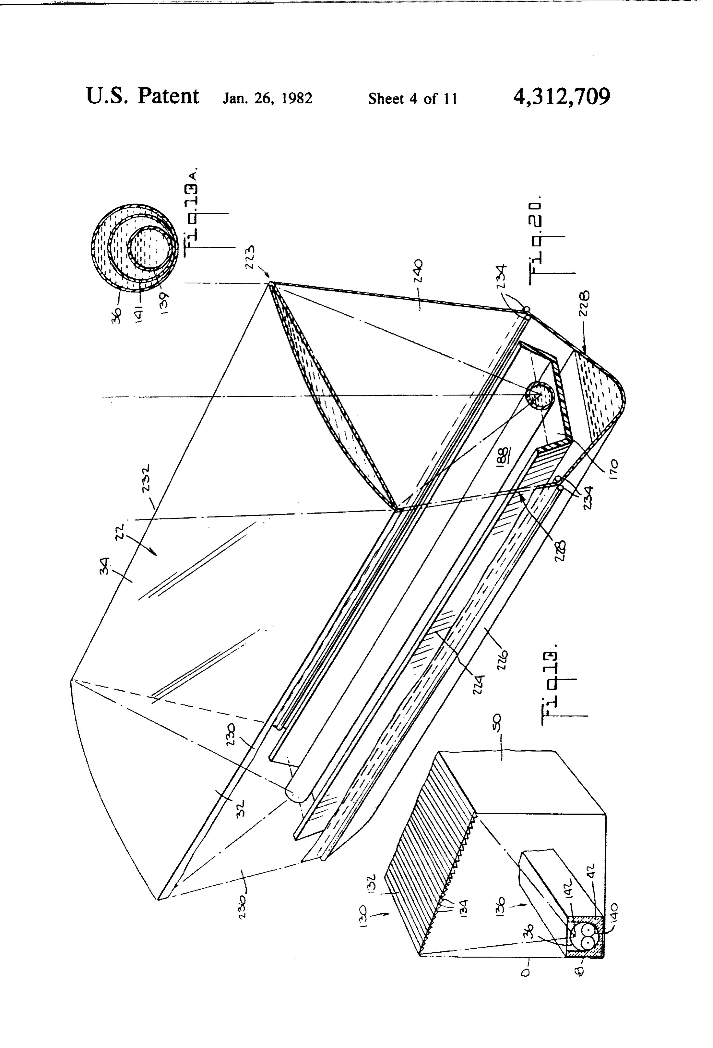
port stringers 94. The lenses may be secured to the System 130 of FIG. 13 is shown employing an elon frame by, for example, adhesives. As shown in FIGS. 7 gated refringent element 132 having longitudinal micro and 8, the theoretical focus 96 of the lenses is at and prisms 134 acting as a longitudinal Fresnel lens. The along collector 98. Means in the form of openings 100 O lens 132 and collector 136 are arranged so that the linear are provided to add and remove fluid 31 and/or air and focus is located at collector 136 which is similar to the openings may be communicated by, for example, collector 24 in FIG. 1 except that two inner conduits tubes 102 to provide for circulation of the fluid. The 138, 140 are enclosed in outer conduit 36. Linear focus openings may be provided in other locations, for exam 142 is located within conduit 36. Providing three con ple, as shown in FIGS. 4–7 and referenced by 100. As 15 duits permits use of three different fluids and allows for mentioned hereinbefore, the plates forming the lenses use of the fluids at varying temperatures for many dif may be integrally extruded or blown or may comprise ferent applications. FIG. 13A shows another arrange separate plates joined as by welding. Referring now to ment for three conduits in which the inner conduit 139 FIGS. 9 and 10, upper curvilinear plate 26 and lower is enclosed by intermediate conduit 141 which in turn is planar plate 28 are separate pieces and are joined in a 20 enclosed by outer conduit 36.
fluid-tight manner by means of frame 104. Frame 104 System 144 in FIG. 14 shows a rectilinear refringent comprises two longitudinal grooves 106, 108. The element 146 formed with longitudinal microprisms 148 upper groove 106 is curvilinear and sized to accommo which direct the solar energy to different linear foci F, date upper curvilinear plate 26 while the lower groove F, F2 located at collector 150 depending upon the is linear and sized to accommodate planar plate 28. The 25 seasonal location of the sun. Collector 150 is located edges of the respective separate plates are inserted into east-west so it is oriented to collect solar energy during the respective grooves along with sealing material 110. daily movement of the sun, and comprises a single solar The ends of the plates are similarly joined. The material energy transmitting, at least at upper part 152, rectangu 110 may comprise a gasket or similar flexible piece lar fluid conduit 154 which is surrounded in part by and/or deformable material such as silicone to form insulating material 42. Parts of system 144 are not fluid-tight joints. Thus, the lenses according to the in shown to proportion. In particular, collector 150 is vention in which two independent plates are joined or shown in larger proportion for clarity and is less than the lenses are extruded or blown, are relatively easy to about 10% of the size of lens 146. A closed system is manufacture and are relatively inexpensive. achieved by extending the sides of refringent element As mentioned hereinbefore, lens 22 may be movable 35 146 and insulating material 42 into overlapping engage to track the seasonal movement of the sun. In FIG. 11, ment. As described hereinbefore, use of a rectangular system 112 is shown in which the side walls 114, 116 are conduit 154 facilitates location of a moving focus such made of expandable plastic whereby the system remains as F, F, F2 within the conduit. Although element 146 enclosed as described hereinbefore upon movement of focuses primarily by refracting the rays of the sun, the lens 22 along a radial axis of the collector. With lens 22 40 microprisms also provide reflection of rays such as 156. in the positions designated by solid lines, walls 114, 116 The inside sides of element 146 may also be suitably assume first positions connected between respective angled and made reflective to reflect any rays imping bottomsides of collector 118 and sides 32, 34 of the lens. ing thereon to the focus.
Upon counter-clockwise rotation of the lens to the posi The present invention may be utilized for many en tion designated by the broken lines, the lengths of the 45 ergy applications as described hereinbefore and may walls are changed and the system remains enclosed. also be advantageously used to distill or otherwise treat Thus, a simple, inexpensive, enclosed system is pro water by evaporation and condensation thereof. Typi vided in which the lens may be moved to track the cally, the water is seawater or brackish water and is to seasonal location of the sun. Still referring to FIG. 11, be desalinated, or water containing minerals or other collector 118 is shown comprising a singel tubular inner 50 substances such as industrial waste water or polluted conduit in which the focus 120 is located. water which is to be purified and distilled. Further in Description of preferred embodiments of the inven accordance with the invention, the refringent concen tion has been made hereinbefore with reference to linear trators and collectors according to the invention are theoretical focus fluid lenses. However, in accordance arranged in systems operative to distill water, prefera with the invention, the solar energy may be concen 55 bly recovering the heat of condensation as described trated by focal point lenses and by solid lenses. In FIG. hereinafter. Preferred embodiments of such systems are 12 is shown a plane refringent element 126 comprising a shown in FIGS, 15-27.
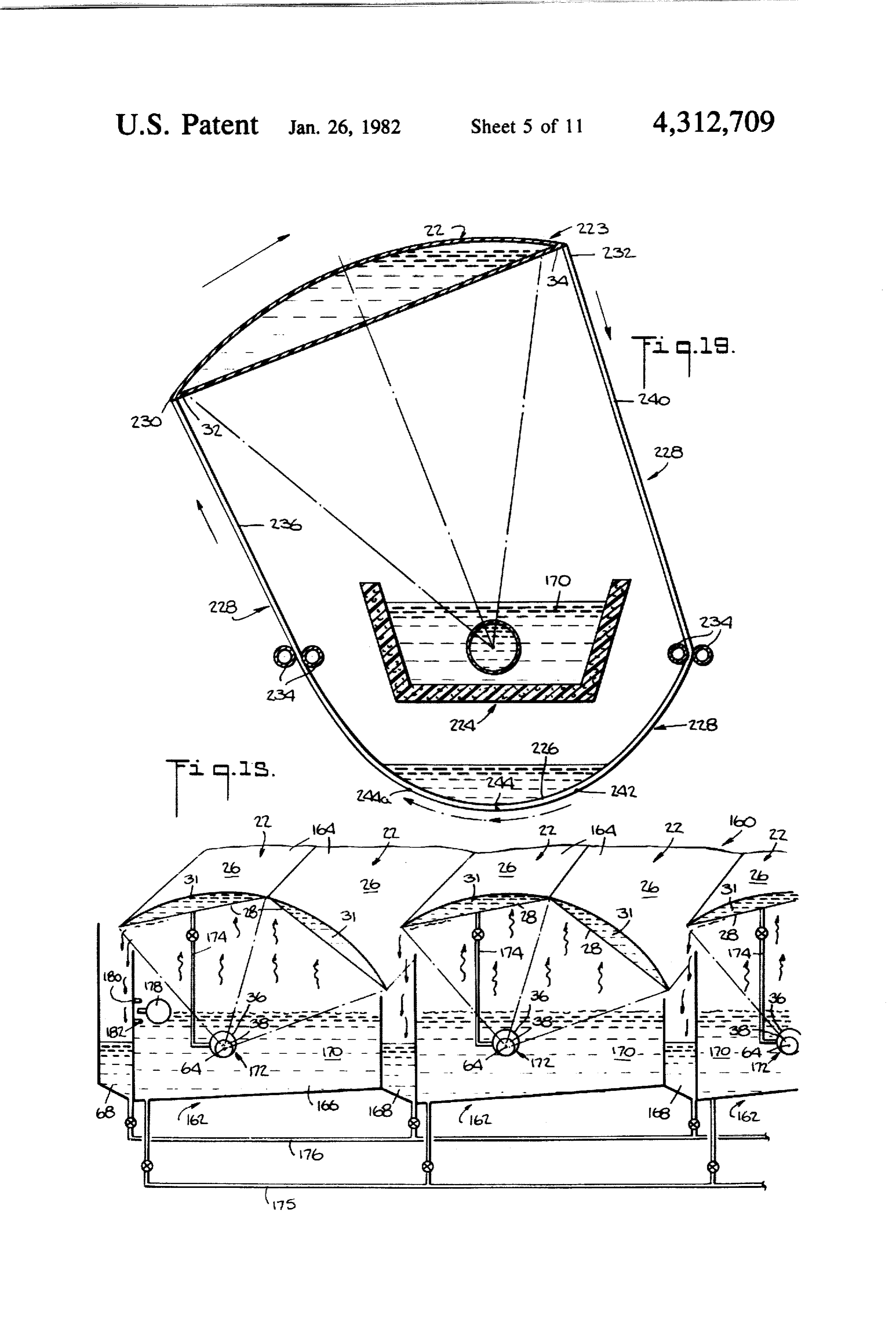
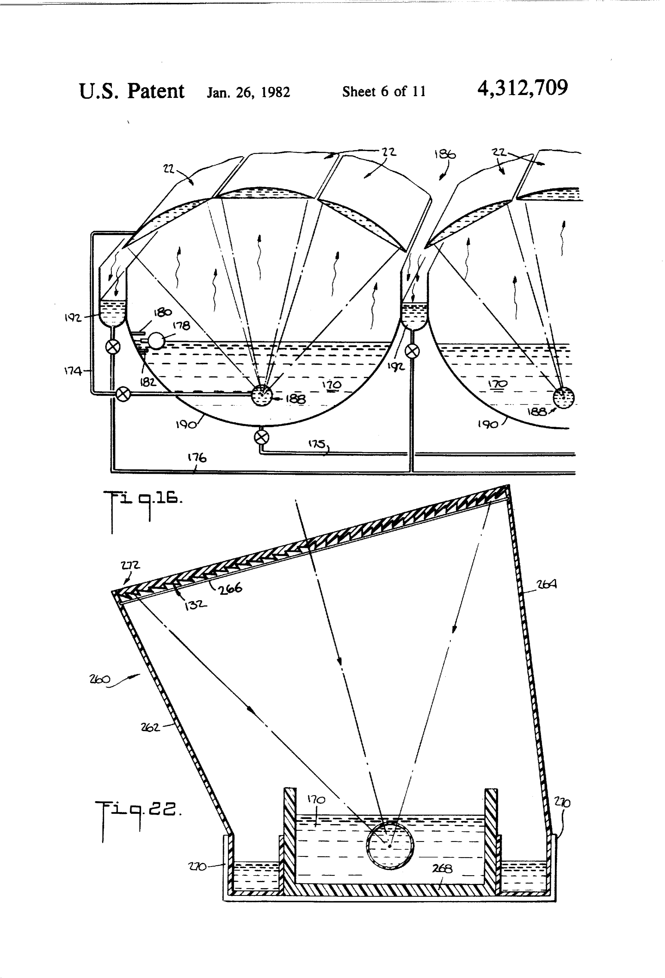
rigid frame 128 surrounding a sheet or plate of plastic or The system 160 shown in FIG. 15 comprises a plural glass material 130 in which are formed by impressions ity of sub-systems 162, each employing a two lens ar or molding concentric closely spaced rings of micro 60 rangement 164 as shown in FIG. 2. Each lens pair 164 is prisms 132 whose pitch, for example, corresponds to supported in a manner similar to that described for FIG. about 3 to about 6 microprisms per millimeter. The 2 above an elongated, central, rectangularly configured plane refringent element 126 acts like a plane Fresnel channel 166 and parallel, elongated, rectangularly con lens. Solar energy striking the refringent element 126 is figured, side channels 168 such that the central part of concentrated by the microprisms into a theoretical 65 the pair of lenses is above the central channels and the point focus (not shown). Refringent elements 126 may outer longitudinal edges of the lenses are above the side be positioned longitudinally juxtaposed as the fluid channels. Each individual lens is inclined and addition lenses in FIG. 7 and/or radially juxtaposed as the fluids ally the pair of lenses is rotated slightly in a clockwise
Page 20
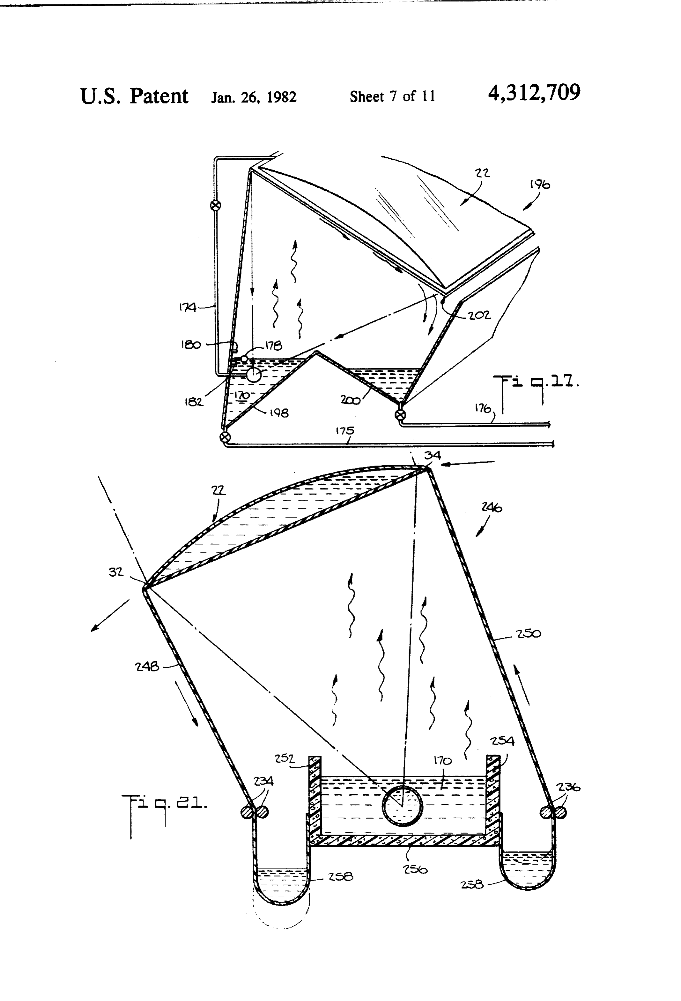
direction such that adjacent pairs are overlapping. The the lens fluid assists in providing a continuous operation bottom lens plates 28 are planar. The water 170 to be system since heat loses are reduced. The water distilla distilled is filled in the central channel to a predeter tion systems described hereinafter operate in similar mined height. Within channel 166 is positioned collec manner and description thereof will therefore be more tor 172 which comprises conduits 36, 38 as in FIGS. limited, 1-3. The focus 64 of the lens pair 164 is located within In FIG. 16 is shown another embodiment (system inner conduit 38, Preferably, the interior of lenses 22 is 186) for treating water 170 employing a three lens ar communicated with collector 172. In the embodiment rangement (and a correspondingly larger area of evapo shown in FIG. 15, lens fluid 31 is advantageously water ration) such as the one shown in FIG. 3 and a collector and the interior of the lenses is communicated by con 0. comprising single conduit 188. Lenses 22 are supported duit 174 with outer conduit 36 in which the fluid is also generally as described for FIG. 15 above central chan water. The fluid in the inner conduit 38 is a higher nels 190 and side channels 192 shown to be semi-cylin boiling point fluid as described hereinbefore. In opera drical. System 186 operates similar to the system shown tion, the water 170 to be distilled is heated by collector in FIG. 15. However, in FIG. 16 only a single conduit 172 due to the solar energy concentrated thereat and the 15 and fluid are used as the heating medium. Advanta water 170 is vaporized. The vapor strikes the lower geously, the central channels are made of concrete and plates 28, is condensed thereon and flows therealong to the side channels of asbestos cement. be discharged at or dropped from the edges thereof into In FIG. 17, a single lens system, single conduit system side channel 168. In accordance with the invention, the 196 is shown which is similar to those described herein water in the fluid lenses is circulated through collector 20 before. The adjacent channels 198, 200 for the water 172. In this way, the heat released by condensation of 170 to be distilled and the distilled water, respectively, the vapor is transmitted through the plate 28 to the are trough-shaped and may advantageously be formed water in the lenses and the heat absorbed by the water from adjacent plates. The inclined lens 22 is above chan in the lens from the condensing vapor is returned to the nels 198, 200 and the lower part of lens 202 terminates system through conduit 36. This is significant because 25 above channel 200 to permit the condensed water to fall the latent heat required to vaporize the water 170 of therein.
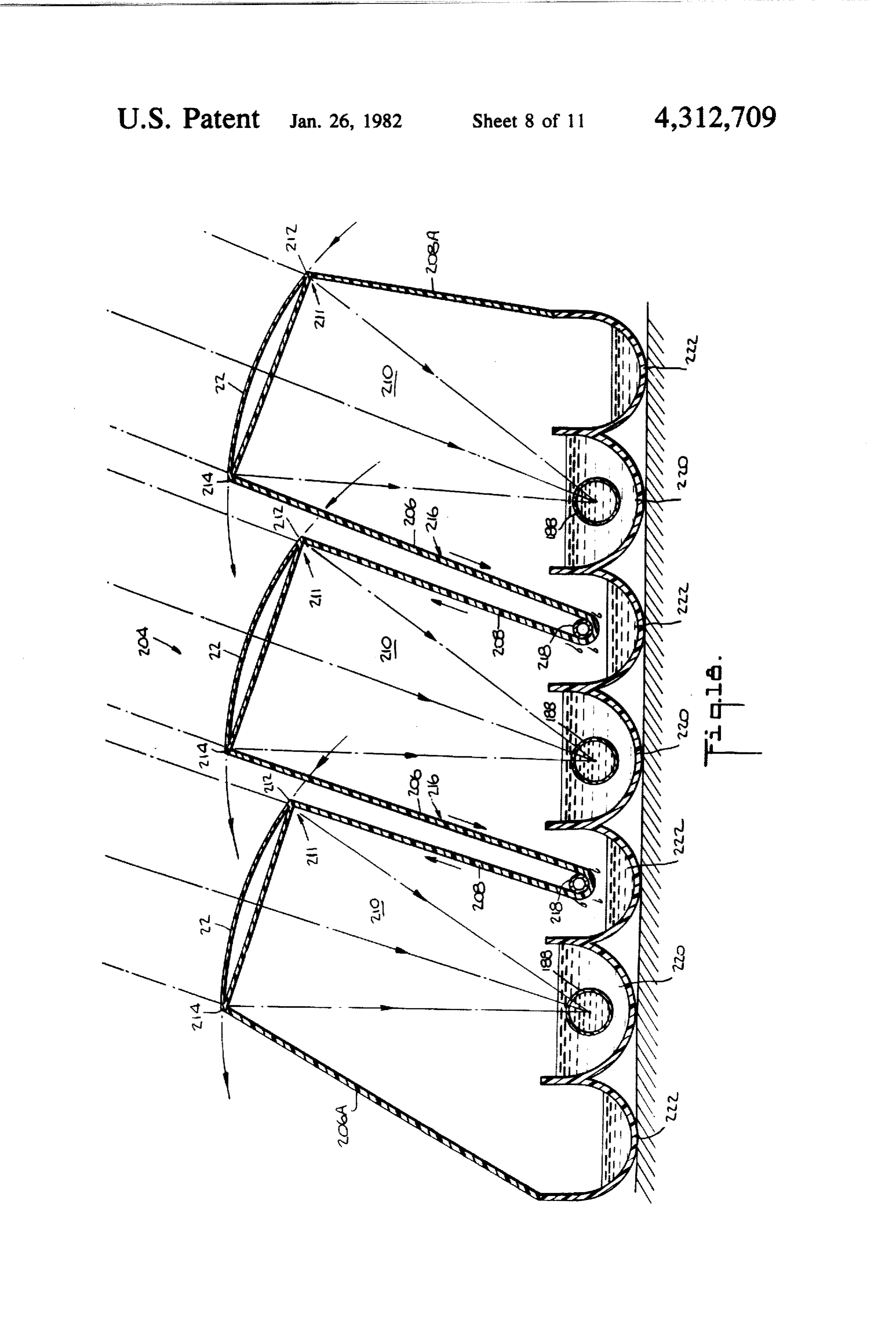
about 539 calories per liter (975 BTU per kilogram) in In FIGS. 18-21 are shown systems of the single lens, addition to the sensible heat is substantially returned to single conduit type described hereinbefore which are the system by the circulated water in the lenses upon maintained essentially enclosed while lenses 22 are which the vapor condenses. This latent heat is substan 30 moved to track the sun. In FIG. 18, an expandable tial and would otherwise be lost. This results in a much material, as described for FIG. 11, forms the side panels higher efficiency of the system compared with solar 206, 208 of each compartment 210 of the system. Ad stills where channels filled with water to be treated are vantageously, the material is of plastic. Opposed ends covered with only glass plates which receive the solar 212, 214 of adjacent side walls 208, 206 are secured to rays. Circulating the water in the lenses also cools the 35 respective sides of lenses 22. Adjacent interior side lower lens plates 28 thereby assisting condensation walls are of one piece and are advantageously formed as thereon. Conduits 175 and 176 are provided for filling a single sheet 216. Sheet 216 is wound partially about and emptying the respective channels. The water 170 to the circumference of tubular members 218 which ex be distilled may be held between predetermined heights tend along longitudinal axes parallel to those of the by a float system comprising float 178 and relays 180 channels 220, 222. The tubular members are secured by and 182. Movement of the float activates respective means (not shown) to maintain sheets 216 as side walls relays to start and stop a pump or motor valve (not 208, 206 as shown. The lower sides 210 of lenses 22 shown). A similar arrangement may be used in side terminate above channels 222. The evaporation and channels 168 or a gravitational drain arrangement may condensation of the water proceeds as described herein be employed to maintain the height of distilled water in 45 before. In addition to enclosing the system, condensed the side channels between predetermined heights. The water flows down side panel 208; and side panels 206, respective channels are communicated to provide ap 208, when cooled by the outside environment, will proximately equal levels in each of the respective chan provide additional condensation of vapor which will nels. Advantageously, the channels are made of con flow down panel 206 as well. The system remains en crete or asbestos cement. Means other than the lens 50 closed upon movement of the lens as follows. If the itself may be used to condense the vapor such as sub lenses are rotated counterclockwise, interior side panels stantially smooth preferably planar plates located below 206 move downwardly and interior side panels 208 the lenses 164. In such a case, the lens fluid may not move upwardly about tubular members 218. The exte recover the latent heat unless the plate is proximate rior side panels 206a and 208a are secured to the sides of thereto. Alternatively, means associated with the plate 55 respective channels 222 and are made of an expandable may be used to recover the latent heat. material as described in FIG. 11. The system shown in FIG. 15 is substantially en - In FIGS. 19 and 20, another system 223 is shown for closed by the channel panels to reduce heat loss as treating water in which the lens 22 is movable and the described hereinbefore. The two-conduit collector 172 system maintained enclosed. A central elongated trough is particularly advantageous since the fluid in the inner 224 holding water 170 to be treated is placed above conduit 38 may be raised to a high temperature and used elongated semi-cylindrical member 226 along parallel to store heat as described hereinbefore. This adds a very longitudinal axes. Member 226 is formed from sheet important capability to the system in that it can operate material 228 which is secured at opposed ends thereof during the night and during periods of reduced sun 230, 232 to respective sides 32, 34 of lens 22. Sheet 228 shine. This is very important in that it provides the 65 extends from one end 230 thereof at lens side 32 down advantage of substantially continuous operation result wardly between longitudinal tubular members 234 to ing in increased system output at reduced cost. The form side wall 236, then downwardly below trough 224 recovery of the latent heat of the condensing vapor by and upwardly between longitudinal tubular members
Page 21
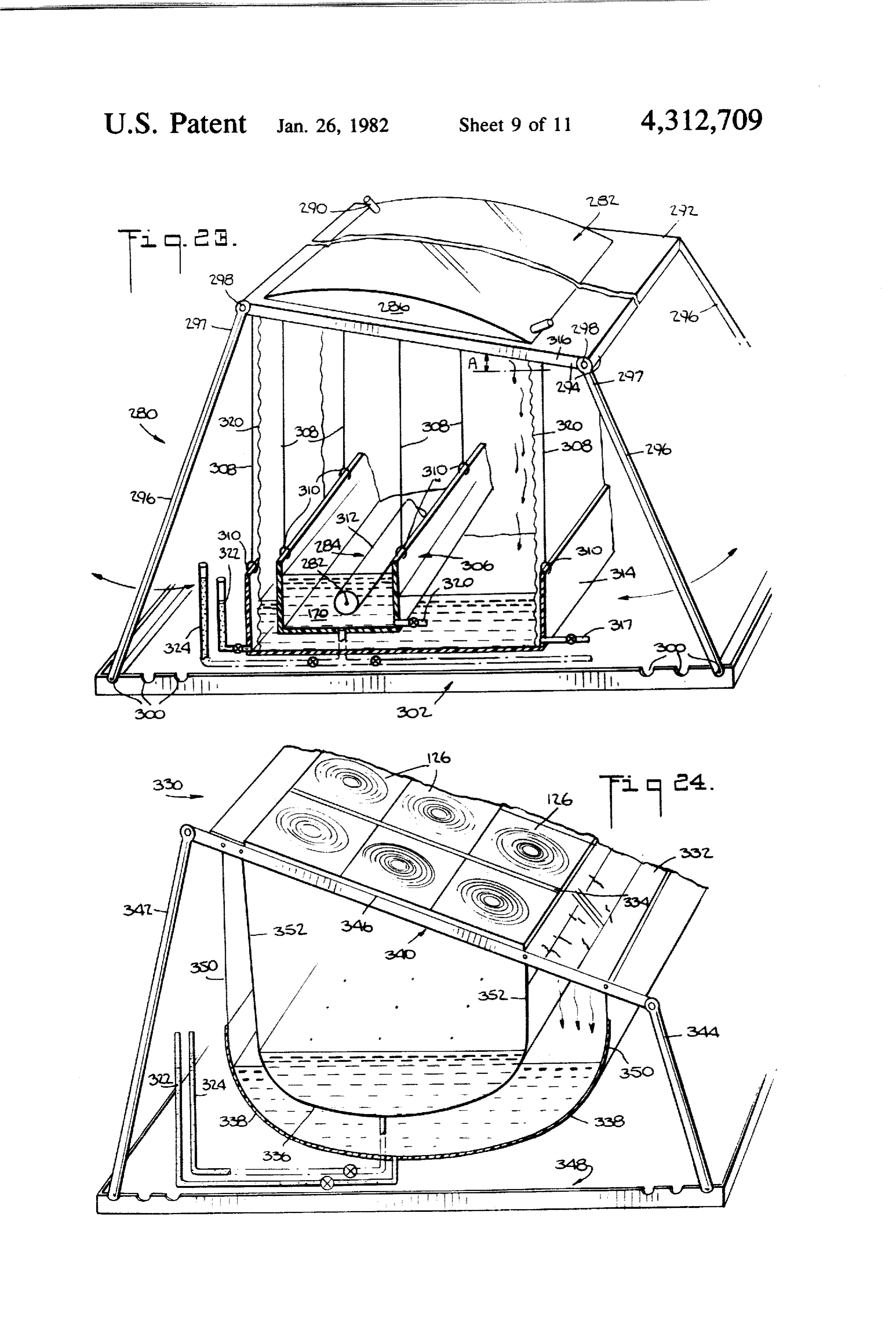
238 to form channel 226, then upwardly to terminate at end 316 of lens 288. Vessel 314 advantageously collaps end 232 at lens side 34 and form side wall 240. Thus, ible and made of lightweight plastic is also hung from system 226 is enclosed by a single sheet member. The upper frame members by cables or ropes 308 and hinges tubular members permit the sheet to slide therebetween 310. Vessel 314 is inclined preferably along the longitu and maintain the width of channel 226. When lens 22 is dinal direction to assist in draining treated water there rotated clockwise, side wall 240 moves downwardly from by means such as valve 317 in outlet 318, Port 320 and side wall 236 upwardly. Point 242 moves down is provided in vessel 306 for filling and emptying. Con wardly to become the bottom of the channel as refer duit 312 is advantageously collapsible and made of enced by 244 while the point previously at the bottom lightweight plastic and is solar energy transmitting, the moves upwardly to be at point 244a. 10 theoretical linear focus of lens 282 being located within In FIG. 21 is shown still another system 246 which is conduit 312. Distillation of water 170 by heating of the maintained enclosed upon movement of the lens. In fluid in conduit 312, advantageously water, and evapo system 246, the side panels 248, 250 are secured at op ration of the water, condensation of the vapor on the posed ends to lens sides 32, 34 and to opposed sides 252, lens and collecting of the condensate proceed as de 254 of central trough 256. The side panels 248, 250 are 15 scribed hereinbefore. Expandable side panels 320 may passed between tubular members 234, 236 in a manner be provided to enclose the system and allow for move similar to that shown in FIG. 21 to form outer channels, ment of lens 282 as described hereinbefore and may be 258 one of which is below lower sides 32 of lens 22. used to form collecting bags as shown in FIGS. 19-22. Movement of the lenses 22 in a counterclockwise direc Means are provided to indicate the water levels in the tion causes side wall 250 to move upwardly reducing 20 vessels 306, 314 such as vertical transparent glass or the size of channel 258 and side panel 248 to move plastic tubes 322,324 located outside side panels 320 and downwardly increasing the size of channel 256. connected by tubing with the bottoms of the vessels. In FIG. 22 is shown a single lens, single conduit sys In FIG. 24 is shown another embodiment of a porta tem 260 employing an elongated, planar Fresnel-type ble water distillation system 330 which is easily assem lens 132 in which the side walls 262, 264 are made of 25 bled and disassembled. System 330 comprises planar expandable material. Lens 132 is supported by solar Fresnel lenses 126 of the type shown in FIG. 12 having energy transmitting glass or plastic support 266 and concentric microprisms causing the solar energy to be inclined with the central part of the lens above elon concentrated at point foci. Lenses 126 are longitudinally gated central channel 268 containing the water 170 to and transversely juxtaposed to form a composite lens be distilled and with lower part 272 above elongated 30 assembly of six Fresnel lenses which is inclined with side channel 270. Vaporization and condensation pro respect to the horizontal, six being chosen for purposes ceed similar to that described for FIG. 18. System 260 is of illustration. The lenses are formed into an assembly maintained enclosed upon movement of lens 132 by by, for example, securing then as by adhesives to a solar stretching and shrinking of side panel 262, 266 as de energy transmitting glass or plastic plate 332 which, in scribed for FIG. 11, opposed ends of the side walls 35 the case of plastic, may be folded along flexible partition being secured to respective sides of the lens and to lines 334. Each Fresnel lens may be about 9 inches by respective parts of channels 270. about 7 inches and are presently available at a cost of Referring now to FIG. 23, a portable water distilla about $0.40 each. The point foci of the lenses are lo tion system 280 is shown comprising elongated fluid cated in the water to be distilled in flexible container or lens 282 and single conduit collector 284. The system is 40 bag 336 made of plastic or other plyable material. Flexi easily assembled and disassembled. Lens 282 is made of ble container or bag 338 made of plastic or other flexible flexible solar energy transmitting material such as clear material located below and extending beyond container plastic and forms an enclosure 286 when inflated by a 336 is used to collect condensate from plate 332. The fluid, advantageously water, which is introduced and lens assembly and containers are supported by support removed and/or circulated by means including inlet 288 45 assembly 340 comprising pairs of legs 342, 344, frame and outlet 290. Air is also removed and introduced 346 and platform 348. The legs are pivotably connected through said means. Lens 280 is supported by frame 292 to frame 346 as described for FIG. 23 to adjust the angle of metal or other suitable material which comprises of incline of the lens assembly to follow the seasonal upper frame members 294 and side support members location of the sun. The containers or bags have side 296. The upper ends 297 of the side support members 50 panels 350, 352 which extend upwards to plates 332 to 296 are pivotably connected to the upper frame mem form an enclosed system as described hereinbefore. An bers 294 as by bolts 298 such that each of the side sup opening is provided in side panel 352 at the lower side port members is pivotable about the bolts in the direc of plate 332 to allow the condensate to drop into the tions indicated by the arrows. Means such as indenta collector bag 338. Means such as transparent tubes 322, tions 300 are provided in platform 302 to secure the 55 324 connected to the bottom of the containers are used lower ends 304 of the side members in selected posi to indicate water levels therein as described for FIG. 23. tions. Alternatively, a platform is not used and ends 304 The lens assembly, support assembly and containers are may be secured in the ground or otherwise. Pivoting of easily assembled and disassembled. The foci located in side members 296 adjusts angle A at which lens 282 is the water to be distilled in container 336 heat the water included for reasons which were described hereinbefore 60 and cause it to evaporate, condensing on the bottom of with respect to FIG. 1. An elongated vessel 306 advan planar plates 332. The condensate moves along plates tageously collapsible and made of lightweight plastic is 332 and falls into container 338. Depending upon loca hung from frame members 294 below the central part of tion, production of distilled water will be about 1 pound elongated lens 282 by cables or rope 308. Hinges 310 are per hour for a system as shown in FIG. 24 having a lens provided to secure the cables to the vessel. Vessel 306 65 surface area of 10 square feet (about 1 square meter). contains the water 170 to be distilled and conduit 312 is This production of distilled water is without recovering disposed within the water. A collecting vessel 314 is the latent heat of condensation. Production of distilled located below vessel 306 and below the lower inclined water could be about six times larger if the latent heat of
Page 22
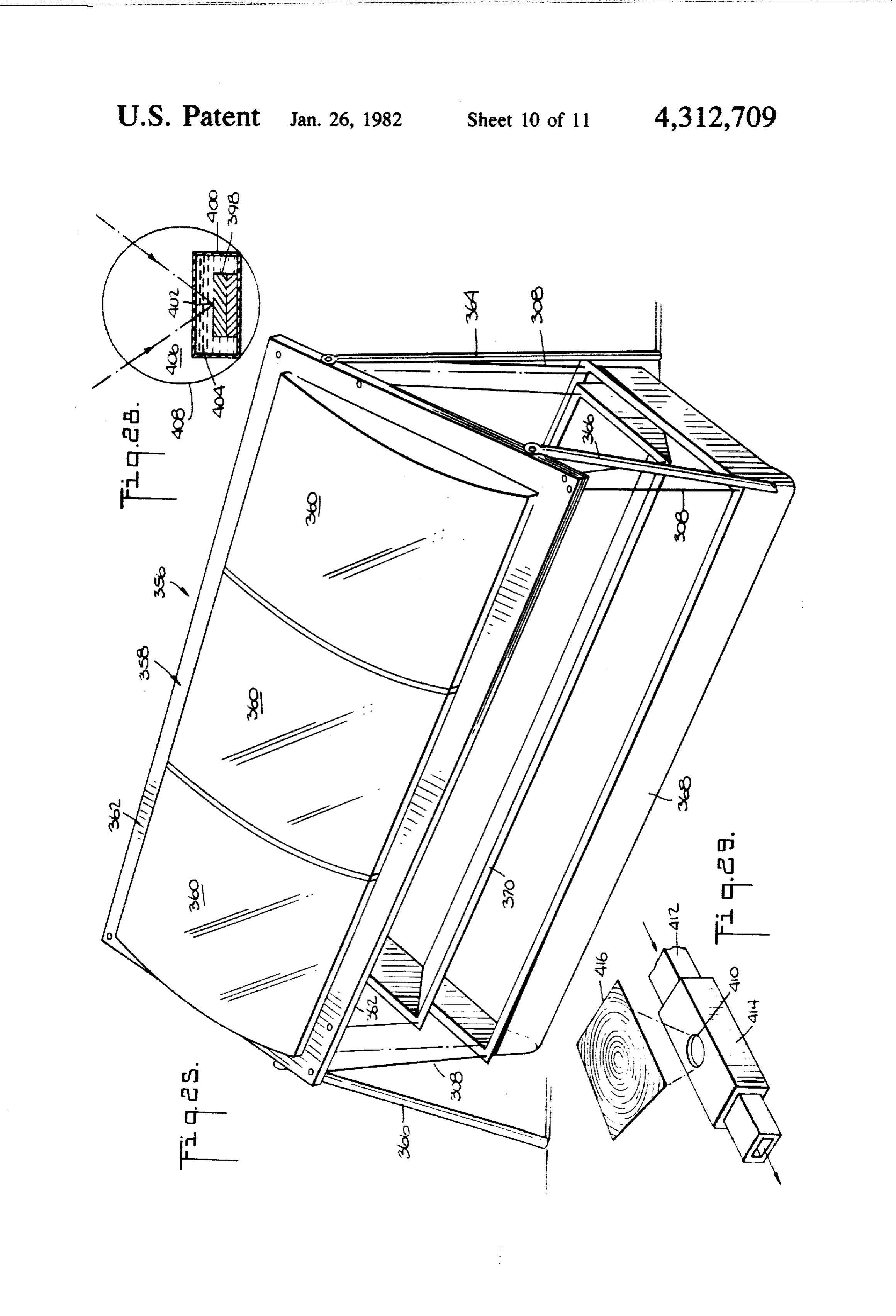
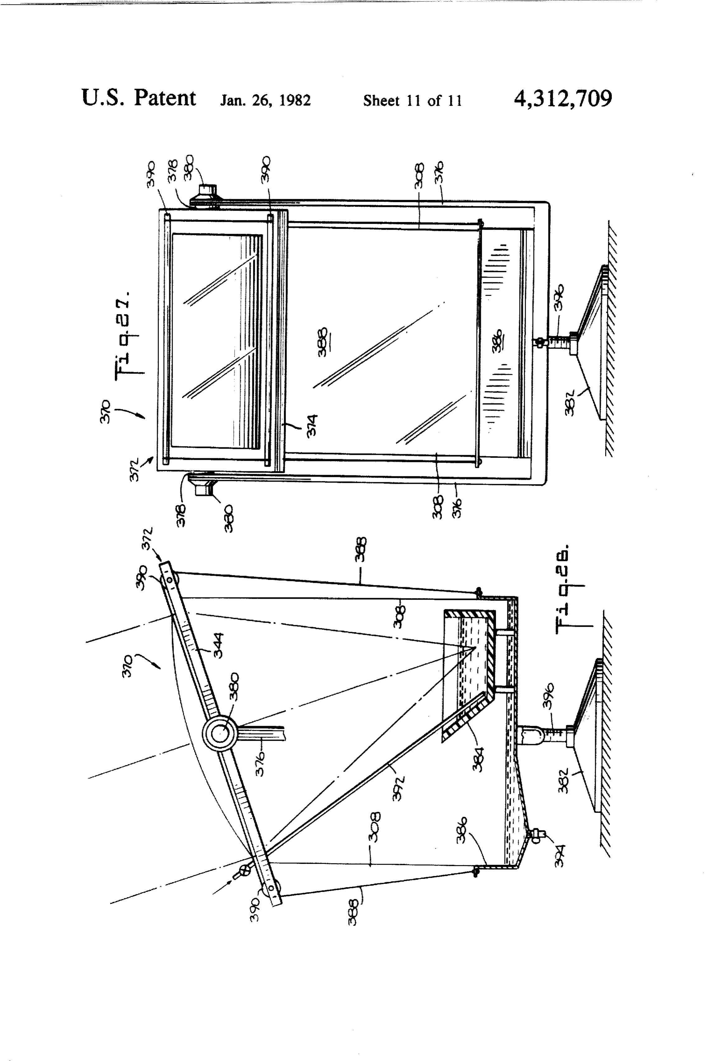
condensation is recovered. As mentioned hereinbefore, fluid 404 is electrically conducting, means (not shown) portable systems can be used at sea or in desert areas. are provided for electrically insulating the cells and the Still another portable distillation system 356 is shown means for interconnecting the cells and for removing in FIG. 25. Lens assembly 358 comprises longitudinally the generated electricity, Conduit 402 has at least its juxtaposed, linear focus, fluid lenses 360 mounted in 5 upper surface mode of transparent material if the theo frame 362. Lenses 360 and lens frame 362 are similar to retical focus 402 is linear or transparent apertures may those described with respect to FIGS. 6-8, the lenses be provided above the cells if the theoretical focus 402 being blown and filled with liquid. The lens assembly is is at a point. The upper part of outer conduit 408 is also supported by pairs of legs 364, 366 which are pivotably transparent. The details of inner and outer conduits connected to frame 358 to change the angle of inclina O have been described hereinbefore.
tion of the lens assembly to follow the seasonal location As mentioned hereinbefore, in accordance with the of the sun. Container 368 for the water to be distilled invention, concentrating the luminous energy of the sun and container 370 for the condensate are supported by with a concentration of up to about 100 permits electric frame 360 by cables or rope 308. ity to be generated at up to about 100 times more power Referring row to FIGS. 26 and 27, another distilla 5 while the increased heat energy is dissipated and re tion systeria 370 is shown. Lens assembly 372 is sup moved by the fluids in the conduits. Electricity may be ported on frame 374 which in turn is pivotably sup generated in conjunction with other uses of solar en ported by U-shaped support member 376. Threaded ergy. For example, referring to FIGS. 1-3, using a dual studs 378 extend from the frame through the support fluid carrying collector, photoelectric cells may be member and threaded knobs or nuts 380 lock the lens inserted therein as just described and electricity gener assembly in position. Member 376 is secured in base 382. ated while the heat energy is being used to heat a struc Containers 384, 386 are supported from frame 374 by tre.
cables or ropes 308. Side panels 388 are provided to An arrangement for using a point focus lens is shown enclose the systern and are movable with respect to in FIG. 29. The theoretical focus is at opening 410 in roliers 390. Water to be distilled is added to container 25
384 by tube 392 and distilled water is removed from ergy transnitting conduit 412 which is made of solar en container 386 by spigot 394. The angle of incline of lens cell may be locatedmaterial. If desired, a photoelectric assembly 372 is changed to follow the seasonal location rial 414 surrounds conduit 412 410.
in opening An insulating nate except at openings 410.
of the sun by loosening threaded knobs or nuts 380 to A point focus fluid lens is referenced by 416. uniock the lens assembly, rotating the lens assembly to a new position, and tightening the knobs to lock the lens CONCLUSION assembly. Pivoting of the lens does not move the con Prominent aspects and advantages of the invention tainers. However, rollers 390 permit movement of the may be summarized as follows: lens assembly with respect to the side panels 388 so that the system remains enclosed. The lens assembly and 35 A lens concentration system is combined with a con duit collector system in which the surface area of the containers are manually rotatable about base 382 as a concentrating unit to further follow the location of the sun as follows, system exposed to the sun is from about 10 to about 100 times larger than the surface area of the
A threaded shaft 396 is rigidly secured to the lower part collecting of the assembly, and base 382 comprises a threaded system through which the energy is concen portion to accept the threaded shaft. This threaded O trated. As a result heat losses are reduced substantially arrangement between the base and the shaft with the since the collector has an area of, for example, only support member connected thereto permit rotation of from about 1% to about 10% of conventional flat plate the shaft and support member about the base. If desired, collector systems and the overall surface area is about non-manual Ireans such as notors can be used to rotate half that of conventional flat plate systems. Thus, the the systein and/or to pivot the lens assembly. 45 efficiency over conventional flat plate systems is in the According to another aspect of the invention, the order of about 50% higher. This reduction in surface concentrated solar energy is used to generate electricity area reduces correspondingly the material requirements by means of photoelectric cells. More particularly, the per unit of surface area exposed to the sun and the in luminous rays of the sun are concentrated on photovo vestment cost is also reduced correspondingly by about taic cells. Referring to FIG. 28, photovoltaic cells 398 50 one-half.
made of silicon of cadmium or other materials are dis More solar energy can be collected by the method posed in the interior of inner fluid-carrying conduit 400 and apparatus according to the invention since the col shown advantageously to be of rectangular cross-sec lector conduits are oriented east-west thereby being tion. The theoretical focus 402 of the iens is at the cells located at the foci of the lenses throughout the day and, and preferably on the outer surface thereof. The cells 55 according to the invention, the lenses can be moved and may be juxtaposed if the theoretical focus 402 is linear positioned at various inclinations to optimally follow or spaced if the theoretical focus 402 is a point focus. the seasonable location of the sun. This positioning of The concentrated luminous rays are converted to elec the lenses can represent up to 40% higher solar energy tricity by the cells while the heat absorbed by the cells collection. Even using auxiliary equipment to adjust the from the infrared rays is removed by the circulating inclination of the lenses, the reduction in investment is fluid 464 and also by the fluid 406 circulating within the in the order of a third over flat panel systems. Not only outer conduit 408. The removal of heat can be con is the investment cost much less than known solar sys trolled by the size of the conduits 402, 406 and by the tems, but the operating cost of obtaining heat energy is volume and rate at which the fluid are circulated. Pref. lower. Also the cost of heat derived from solar energy erably fluid 44 is substantially electrically non-conduc 65 according to the invention is lower and may be up to tive such as air or other gases and liquids. Means (not one-third lower than the cost of petroleum fuels based shown) are provided for connecting the cells in parallel on the usable heat content. This is of great importance of series and for removing the generated electricity. If to oil importing countries. Additionally, solar energy is
Page 23
inexhaustable and does not produce pollution as does used as fuel for automobiles, airplanes, etc. The system the burning of other fuels. described hereinbefore could be combined with known According to the invention, by concentrating the heat pumps to further utilize the collected solar energy solar energy at elongated conduits, higher tempera in combination with the heat provided by the heat tures, for example, exceeding 200 C. (392 F.) are at pumps, particularly for refrigeration systems. In addi tainable using high boiling temperature fluids in the tion to providing energy for heating, the systems ac conduits such as lubricating oil, glycerine, etc. This is to cording to the invention could be used for air condition be compared with to about 80 C. (176 F.) attainable by ing and, as just mentioned, in refrigeration systems. flat plate systems. According to the invention, multiple Also, the multi-conduit collectors and fluids are capable conduits, either conduit receiving the foci of the lenses, O of providing temperatures of about 70° C. to about 80” allows storing solar heat to be used for hours without C. for heating rooms and for heating water, and at sunshine. The invention provides for storage of heated higher temperatures, for example, about 180° C. to fluids in the inner conduit at high temperature, for ex about 200° C., for heat storage applications and to pro ample, over 200° C. which heats the outside fluid to duce electricity.
lower temperatures, for example, 80 C. Using this ar 15 The apparatus according to the invention has been rangement permits a reduction in storage volume re described primarily using schematic diagrams. Accord quired by the higher temperature fluid over fluids at ingly, certain details not essential to an understanding of about 80 C. According to the invention, low boiling the invention have been omitted. For example, the ma point and low latent heat of vaporization fluids such as terials and support structure comprising the apparatus freon, ether, etc. are used in the conduits which fluids 20 according to the invention not described in detail will are vaporized and superheated by the solar energy and be known to those skilled in the respective arts. The used to produce electricity in expansion motors such as sizes of the parts of the apparatus described hereinbe turbines at lower cost than using fuel. fore will vary depending on the use to which the appa Electricity may also be produced according to the ratus is put. For example, the lenses in FIG. 3 may each invention with photovoltaic cells where the increased 25 be 60 inches wide for a total radial width of 180 inches solar energy concentration of up to 100 times increases for three lenses. The conduit in a single conduit collec substantially the electric production and correspond tor may be a tube 2 inches in diameter wherein the ingly reduces the cost of electricity. Several circulating concentration of the lenses on the tube is in the order of fluids in several conduits are employed to remove the 90. In a two conduit collector system, where the inner heat developed by the concentrated infrared solar rays. 30 fluid is lubricating oil heated to about 200° C., the space Employing several fluids according to the invention required to store an equal amount of heat will be about permits simultaneous use for many purposes such as 23 times less than for a fluid such as water heated to 80 heating water, heating buildings, air conditioning, pro C. Also, the multiple conduit system permits multiple ducing electricity, etc. uses for the heats of the different fluids. For example, a An advantage of the present invention over reflecting 35 fluid heated to about 200 C. may be used to heat build systems is that diffuse sun energy of up to about 40% ings and a fluid heated to about 70° C. to 80° C. may be can be collected. Reflecting systems generally require used for heating water. As shown in FIGS. 2, 3, 7, 8, 15, costly tracking equipment to follow the location of the 16, 18, many fluid lens may be radially and longitudi sun and such reflective systems are more expensive for nally juxtaposed to form composite systems from indi this and other reasons including maintenance of the vidual systems or very large systems. The Fresnel-type reflective surfaces. lenses may have similar length and width dimensions Further according to the invention water containing and may be similarly employed in composite or large salt or other substances is distilled using solar energy systems. Portable distillation units may be used, for collection and concentration according to the invention example, as mentioned hereinbefore, in lifeboats to dis and recovering a large part of the latent heat of vapori 45 till sea water or in desert areas to distill brackish water zation and sensible heat (about 1100 BTU/lb or 600 and thereby possibly save lives. Portable units accord cal/kg). This is accomplished by using the fluid circu ing to the invention could produce, for example, one lating in the lens system to recover the latent heat and pound of distilled water for every square meter (about circulating the fluid in the conduit in the water to be 10 square feet) of lens concentrator area exposed to the distilled thereby heating the water to be distilled. The 50 sun's rays, and this without recapturing the heat of salt from the concentrated brine may also be recovered condensation. The production of distilled water, how and sold or electrolyzed. Distillation according to the ever, will be about six times as great if the heat of con invention is at low cost such that water may be pro densation is recovered.
duced for irrigation purposes. The invention provides It is pointed out that the heat obtained from the sun for portable dismountable distillation units which could 55 using the energy systems according to the invention be used to distill sea water in lifeboats or brackish water may be lower in cost than heat energy obtained from in arid desert areas thereby possibly saving lives. fuels which may thus be replaced. Heat storage pro While specific applications of the invention have been vided by systems according to the invention is a feature described, many are uses of the collected solar energy which also makes these systems competitive with fuels. are possible. For example, the salt by-product of descli The distillation systems according to the invention are nation may be collected and sold to reduce the over-all capable of providing distilled water at low cost and operating cost of the system. Additionally, the salt may therefore are important where clean water is scarce. be separated into sodium and chlorine by electrolysis by The advantages of the present invention, as well as electricity generated by the solar energy collecting certain changes and modifications of the disclosed em system. In this respect, water can be separated into 65 bodiments thereof, will be readily apparent to those hydrogen and oxygen also by electrolysis, the hydrogen skilled in the art. It is the applicant's intention to cover of which in turn may be used in the manufacture of by their claims all those changes and modifications liquid methanol which is easily transported and may be which could be made to the embodiments of the inven
Page 24
tion herein chosen for the purposes of the disclosure 6. The apparatus of claim 5, wherein said outer con without departing from the spirit and scope of the in duit is solar energy transmitting at least in part and is vention. adapted to pass concentrated solar energy therethrough What is claimed is: such that said line is located within said outer conduit. 1. Apparatus for distilling liquids including water 5 7. The apparatus of claim 5, wherein said inner con using solar energy, comprising container means for duit and said outer conduit are solar energy transmitting holding liquid to be distilled, an elongated fluid lens for at least in part, said solar energy-transmitting parts of concentrating solar energy in said container means, said said inner and outer conduits being aligned and being fluid lens having upper and lower solar energy-trans adapted to pass concentrated solar energy therethrough mitting lens plates and a solar energy-transmitting fluid O such that said line is located within said inner conduit. enclosed by said lens plates and means for admitting 8. The apparatus of claim 5, and further comprising fluid to and withdrawing fluid from said fluid lens such means for communicating the interior of said fluid lens that said fluid can be passed through said fluid lens, said means with one of said inner and outer conduits. fluid lens being disposed above said container means 9. The apparatus of claim 4, wherein said container and positioned such that rising evaporated liquid from 5 means comprises a first container for containing the said container means impinges upon said lower lens water to be distilled and wherein said water collecting plate and is condensed thereon, said lower lens plate means comprises a second container.
being operative to transmit at least in part the heat of 10. The apparatus of claim 9, and further comprising condensation released by evaporated liquid condensing means for adding water to be distilled to said first con thereon to said fluid in said lens, and said fluid being 20 tainer and means for removing distilled water from said operative to absorb at least in part the heat transmitted second container, said means for adding water compris by said lower lens plate, said fluid lens being inclined ing means for automatically maintaining the level of with respect to the horizontal such that condensed liq water in said first container within predetermined lim uid flows along said lower lens plate to a vertically its, and said means for removing water comprising lower portion thereof and is discharged therefrom, and 25 means for automatically maintaining the level of water liquid collecting means disposed below said lower por in said second container between predetermined limits. tion of said lower lens plate for collecting condensed 11. The apparatus of claim 9, wherein said apparatus liquid discharged from said lower portion. comprises a plurality of apparatus including a plurality 2. The apparatus of claim 1, and including means for of first containers, a plurality of second containers and removing heat absorbed in said fluid which is passed a plurality of lens means arranged in a parallel manner, through said fluid lens. adjacent first containers being separated by a second 3. The apparatus of claim 1, and including means for container which is common to adjacent apparatus. removing heat absorbed by said fluid which is passed 12. The apparatus of claim 9, and further comprising through said fluid lens and for transferring at least part insulating means for enclosedly insulating the volume of said heat to said liquid to be distilled. 35 between said first and second containers and said lens 4. The apparatus of claim 3, wherein the liquid to be C2S.
distilled is water. 13. The apparatus of claim 9, and further comprising 5. The apparatus of claim 1 and further comprising means for easily assembling and disassembling said ap elongated solar energy collector means comprising a paratus for distilling water.
plurality of elongated conduits through each of which a 40 14. The apparatus of claim 1 and including a plurality fluid can be passed, said conduits being disposed in said of fluid lenses juxtaposed about a radial axis of said container means along parallel axes which are substan apparatus.
tially parallel to the elongated axis of said fluid lens 15. The apparatus of claim 1 and including a plurality means, an inner of said conduits being disposed within of fluid lenses juxtaposed along a longitudinal axis of an outer of said conduits and said line being located in 45 said apparatus. e s sk or on one of said inner and outer conduits.
Provenance
- Collection
- Patents citing this work
- Original assignee
- North American Utility Construction Corp
- Pages
- 24
- Method
- pdftotext (the PDF's own text layer) + pdftoppm 300dpi page scans
- Patent office record
- patents.google.com →
- Source
- Google Patents citing-documents table
- Inventors
- Virgil Stark; Alexandre Vayda; Paul Rousset; North American Utility Construction Corp
- Published
- 1982-01-26
- Transcribed from
- patentimages.storage.googleapis.com →