Figure (1-3)
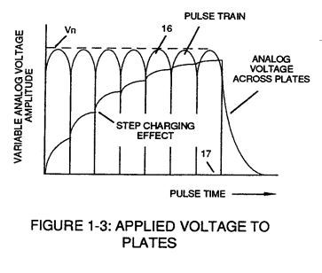
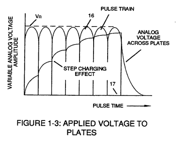
Applied Voltage To Plates
How it is written
- (1-3) 13×
Drawings 6
-
Figure (1-3) · LC Circuit
-
Figure 1-3 · Amp Inhibiting Circuit Vs Voltage Enhancement
-
Stanley A. Meyer Page 10 of 28 · WFC 417 — WFC 417
-
Beside the passage · Voltage Performs Work
-
Beside the passage · ATOMIC INTERACTION TO VOLTAGE STIMULATION
-
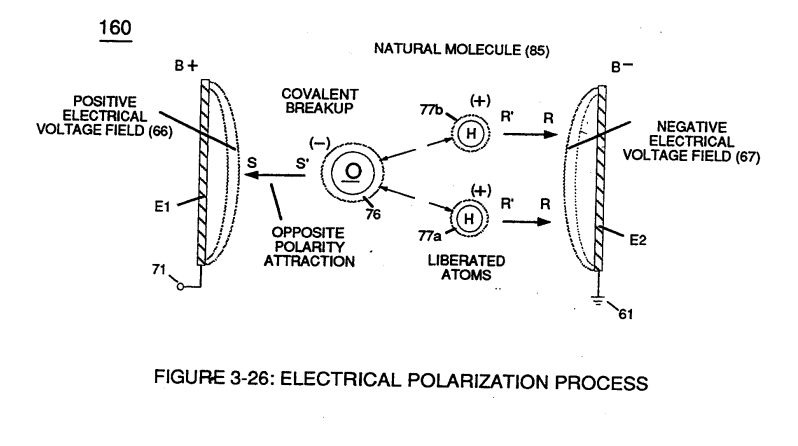
(160) of Figure (3-26) · Propagating Electrical Stress
On this figure 1
Where it is named · 13
WFC 417 — WFC 417 3×
-
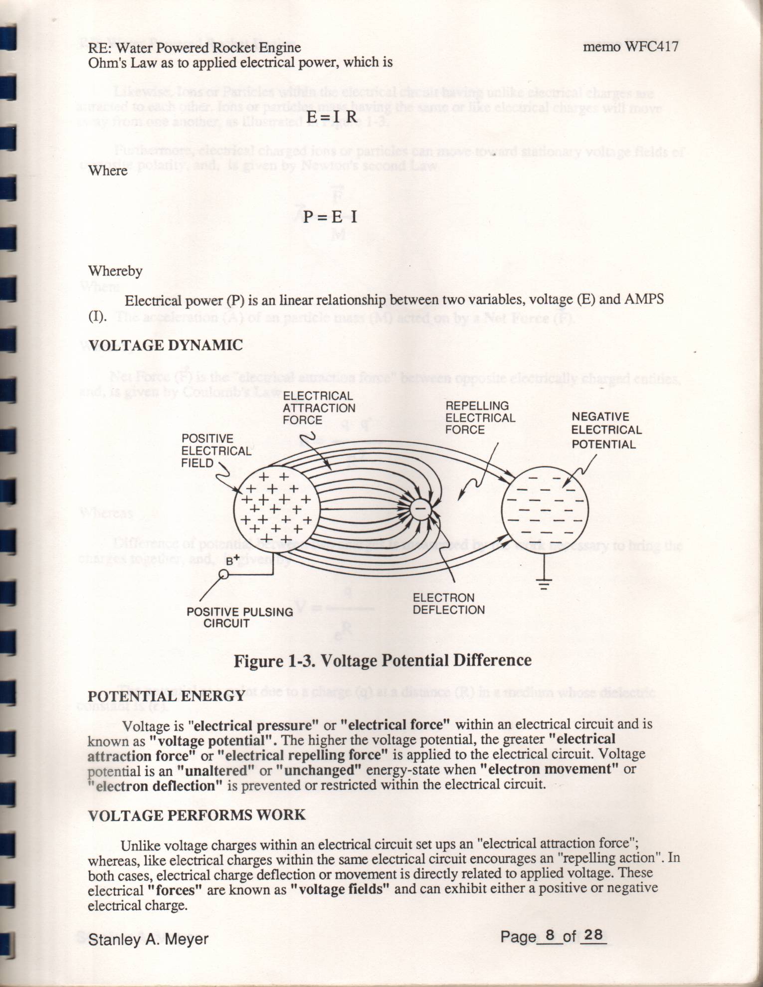
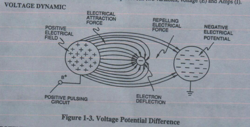
Figure 1-3. Voltage Potential Difference
-
Likewise, Ions or Particles within the electrical circuit having unlike electrical charges are attracted to each other. Ions or particles mass having the same or like electrical charges will move away from one another, as illustrated in Figure 1-3.
-
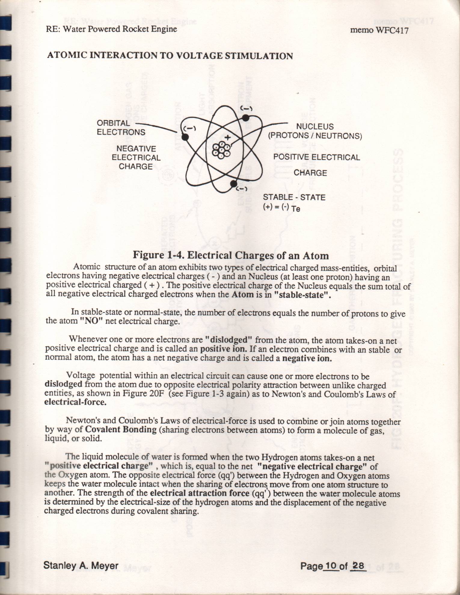
Voltage potential within an electrical circuit can cause one or more electrons to be dislodged from the atom due to opposite electrical polarity attraction between unlike charged entities, as shown in Figure 20F (see Figure 1-3 again) as to Newton's and Coulomb's Laws of
VOLTAGE DYNAMIC 1×
-
Figure 1-3. Voltage Potential Difference
Voltage Performs Work 1×
-
Likewise, Ions or Particles within the electrical circuit having unlike electrical charges are attracted to each other. Ions or particles mass having the same or like electrical charges will move away from one another, as illustrated in Figure 1-3.
ATOMIC INTERACTION TO VOLTAGE STIMULATION 1×
-
Voltage potential within an electrical circuit can cause one or more electrons to be dislodged from the atom due to opposite electrical polarity attraction between unlike charged entities, as shown in Figure 1-5 (see Figure 1-3 again) as to Newton's and Coulomb's Laws of electrical-force.
LC Circuit 2×
-
The established resonant frequency is, of course, independent of voltage amplitude, as illustrated in Figure (1-3) as to Figure (1-4).
-
Figure (1-3)
LC Voltage 2×
-
Figure (1-3)
Amp Inhibiting Circuit Vs Voltage Enhancement 2×
-
Pulse-Voltage repetition rate sets up the step-up electrical charging effect (Figure 1-3) since the "Resonant Cavity" functions as a Capacitor ER) due to the dielectric value (Resistance to amp flow) of water which becomes an integral part for the VIC Circuit, as so illustrated in (650) of Figure (7-4).
-
Figure 1-3