(AA)
Voltage Intensifier Circuit
Also written pulsing circuit · circuit
Where it is first named
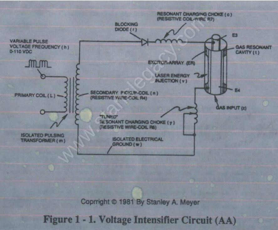
Figure 1 - 1. Voltage Intensifier Circuit (AA)
How it is written
- (AA) 11×
Drawings 13
-
Stanley A. Meyer Page_2 of 28 · WFC 417 — WFC 417
-
Stanley A. Meyer Page_6 of 28 · WFC 417 — WFC 417
-
Stanley A. Meyer Page 12 of 28 · WFC 417 — WFC 417
-
Operational Parameters · RE: Electrical Particle Generator
-
The primary coil is electrically isolated (no electrical connection between primary and secondary coil) to form Voltage Intensifier Circuit (AA) Figure (1-1). · Pulsing Transformer
-
Figure (1-1) (Memo WFC 420) · Instant Explosion of Water
-
(E1/E2) of Figure (1-1) page (1-13) · Taper Resonant Capacitor (ERt)
-
Figure (1-1) · Propagating Electrical Stress
-
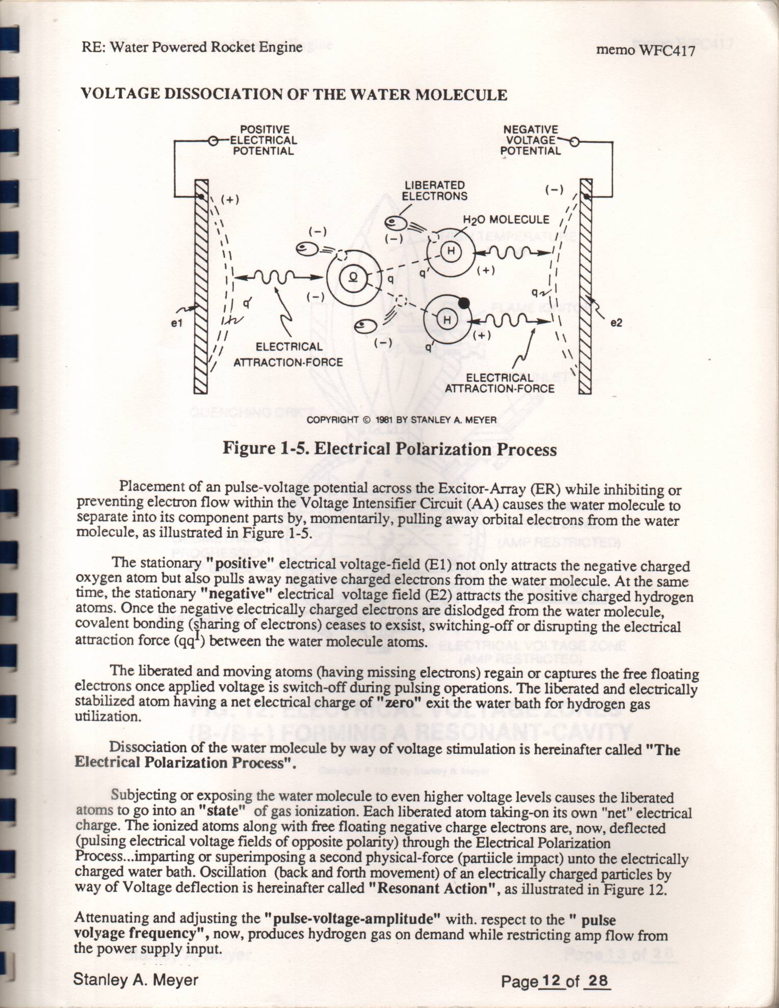
weakening the electrical attraction-force (qq') between the orbital electrons and the nucleus, as illustrated in Figure 1-5 as to Figure 20JX. · LASER INTERACTION
-
Figure (1-5) · LC Voltage
-
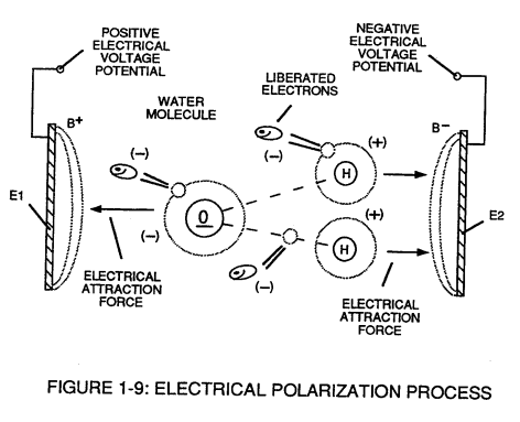
The stationary "positive" electrical voltage-field (E1) not only attracts the negative charged oxygen atom but also pulls away negative charged electrons from the water molecule. · Voltage Dissociation of The Water Molecule
-
The figure it sits on · Electronic Circuit Design
-
Water Fuel Injection System (10) of Figure (1) · Water Fuel Injector (Taper Resonant Cavity Chamber)
Where it is named · 11
WFC 417 — WFC 417 4×
-
Voltage Intensifier Circuit (AA)
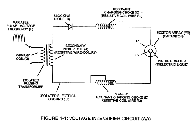
Figure 1 - 1. Voltage Intensifier Circuit (AA)
-
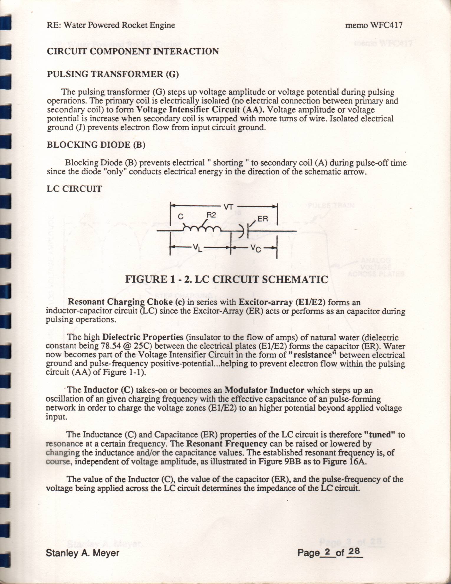
The high Dielectric Properties (insulator to the flow of amps) of natural water (dielectric constant being 78.54 @ 25C) between the electrical plates (E1/E2) forms the capacitor (ER). Water now becomes part of the Voltage Intensifier Circuit in the form of "resistance" between electrical ground and pulse-frequency positive-potential...helping to prevent electron flow within the pulsing circuit (AA) of Figure 1-1).
-
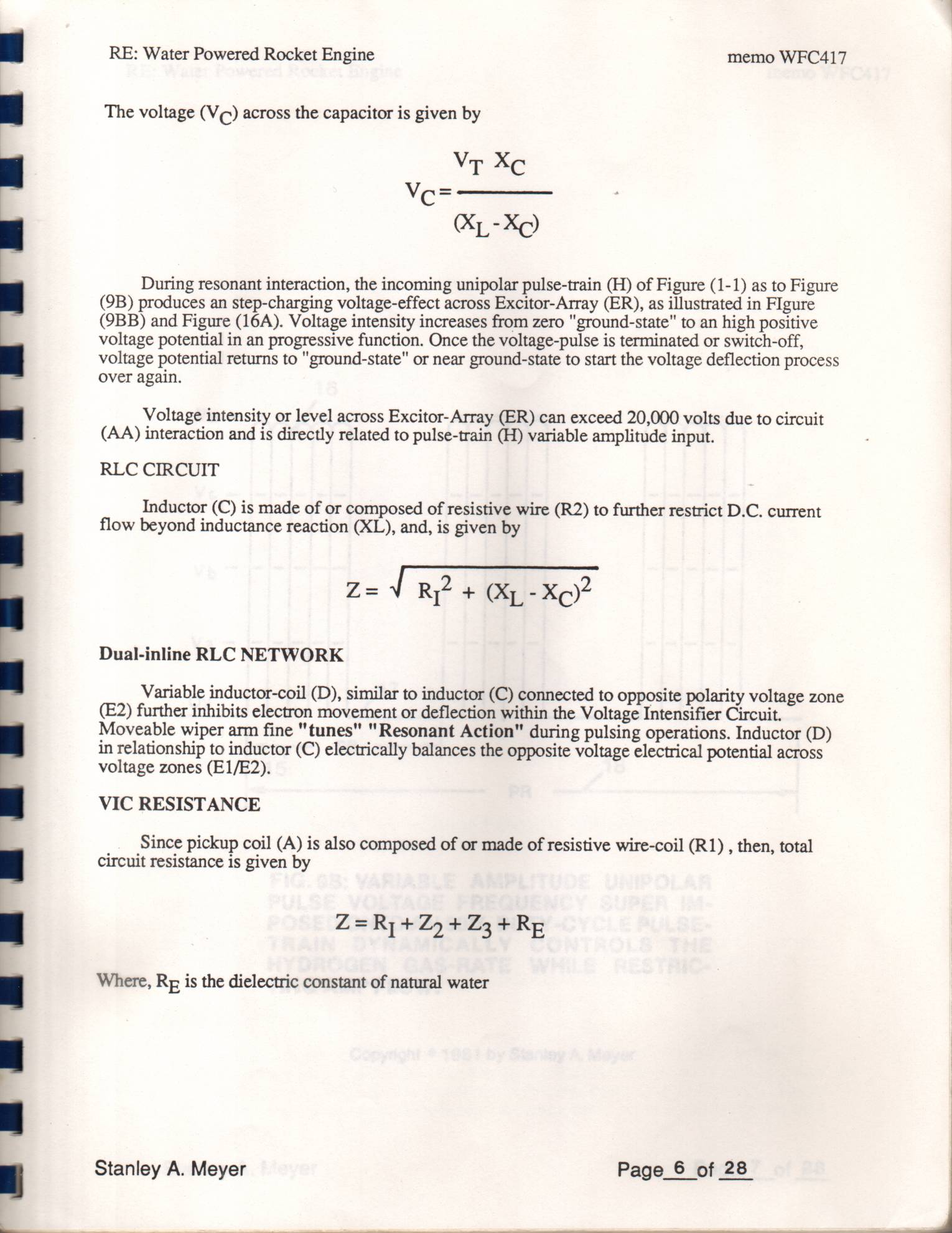
Voltage intensity or level across Excitor-Array (ER) can exceed 20,000 volts due to circuit (AA) interaction and is directly related to pulse-train (H) variable amplitude input.
-
Voltage Intensifier Circuit (AA)
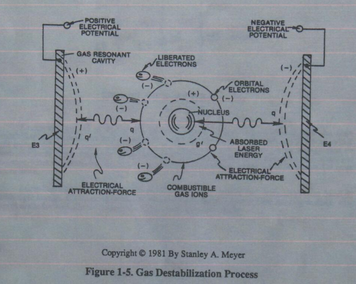
Placement of an pulse-voltage potential across the Excitor-Array (ER) while inhibiting or preventing electron flow within the Voltage Intensifier Circuit (AA) causes the water molecule to separate into its component parts by, momentarily, pulling away orbital electrons from the water molecule, as illustrated in Figure 1-5.
CIRCUIT COMPONENT INTERACTION 1×
-
pulsing circuit (AA)
Gas Molecule or Gas atom of Argon (Ar) now becomes part of the Voltage Intensifier Circuit in the form of “resistance” between electrical ground and pulse-frequency positive-potential... helping to prevent electron flow within the pulsing circuit (AA) of Figure 1-1.
RLC CIRCUIT 1×
-
circuit (AA)
Voltage intensity or level across Excitor-Array (ER of t) can exceed 20,000 volts due to circuit (AA) interaction and is directly related to pulse-train (h) variable amplitude input.
Gas Destabilization Process 1×
-
Voltage Intensifier Circuit (AA)
Placement of a pulse-voltage potential across the Excitor-Array (ER) of Gas Resonant Cavity (t) while inhibiting or preventing electron flow within the Voltage Intensifier Circuit (AA) causes the Gas Atom of Argon (Ar) to become an positive charged ion by pulling away orbital electrons from the gas molecule or gas atom, as illustrated in Figure 1-5.
Pulsing Transformer 1×
-
Voltage Intensifier Circuit (AA)
The primary coil is electrically isolated (no electrical connection between primary and secondary coil) to form Voltage Intensifier Circuit (AA) Figure (1-1).
LC Circuit 1×
-
pulsing circuit (AA)
... helping to prevent electron flow within the pulsing circuit (AA) of Figure 1-1.
LC Voltage 1×
-
Voltage intensity or level across Excitor-Array (ER) can exceed 20,000 volts due to circuit (AA) interaction and is directly related to pulse-train (H) variable amplitude input.
Voltage Dissociation of The Water Molecule 1×
-
Voltage Intensifier Circuit (AA)
Placement of a pulse-voltage potential across the Excitor-Array (ER) while inhibiting or preventing electron flow from within the Voltage Intensifier Circuit (AA) causes the water molecule to separate into its component parts by, momentarily, pulling away orbital electrons from the water molecule, as illustrated in Figure (1-9).