patent · US5711865
Electrolytic gas producer method and apparatus
27 January 1998
Page 1 — bibliographic record
United States Patent 19 11 Patent Number: 5,711,865 Caesar 45) Date of Patent: Jan. 27, 1998 54 ELECTROLYTIC GAS PRODUCER METHOD 3,311,097 3/1967 Mittelstaedt ........................ 204/278 X AND APPARATUS 4,206,029 6/1980 Spirig ...................................... 204/268 4,424,105 1/1984 Hanson ... ... 204/278 X 75 Inventor: Mervyn Leonard Caesar, Runaway 4,450,060 5/1984 Gonzalez ... ... 204/270X Bay, Australia 4,747,925 5/1988 Hasebe et al. ... ... 204/270 5,037,518 8/1991 Young et al. ... ... 205/628 (73) Assignees: Rhyddings Pty Ltd, Robina; Renjean 5,082,544 1/1992 Willey et al. ........................... 204/270 Pty Ltd, Kenmore, both of Australia 5,211,828 5/1993 Shkarrand-Moghaddam ...... 204/278 X
22, PCT Filed: Mar 2, 1994 Primary Examiner -Donald R. Valentine 86 PCT No.: PCT/AU94/00092 Attorney, Agent, or Firm-Dvorak & Orum S371 Date: Oct. 10, 1995 57 ABSTRACT S 102(e) Date: Oct. 10, 1995 Electrolytic gas producer apparatus is provided wherein a 87 PCT Pub. No.: WO94/21844 water inlet has a pressure sensor and solenoid valve control passes water through a filter by pump to a reservoir. Cell
PCT Pub. Date: Sep. 29, 1994 chambers maintain electrolyte by supply pump and solenoid 30 Foreign. Application Priority Data valve delivering to the cell via solenoid valves responsive to a level sensor. Gas outlet apertures extend into a polling
Mar 15, 1993 IAU Australia ................................. PL782.5 manifold via solenoid valves and thence to a wash tank. The (51] Int. Cl. ... C25B 1/06; C25B 15/08; gas is removed from the tank via a manifold to a vacuum C25B 9/00 pump which draws the gas through a first filter including a 52 U.S. Cl. ......................... 205/628; 204/228; 204/229; drain line and a secondary filter for residual moisture 204/270; 204/277; 204/278; 204/292; 204/293; removal. After the pump the gas passes under water in a 204/290 R; 204/279; 204/284; 204/294 flashback arrester filled with metal mesh. The gas then (58) Field of Search .............................. 204/278, 270, travels to a moisture removing filter and delivery pumps for 204/228, 229, 290 R, 284, 294, 293, 292, delivery via intermediate solenoid valves, an outlet 277; 205/628, 633, 637 manifold, and final solenoid valves which control delivery to an electronically monitored outlet flashback arrester com 56 References Cited prising infrared sensors to detect and signal a flashback condition.
3,310,483 3/1967 Rhodes ................................ 204/278 X 20 Claims, 15 Drawing Sheets
Page 2
Drawing sheet — no readable text.
Page 3
Drawing sheet — no readable text.
Page 4
Drawing sheet — no readable text.
Page 5
Drawing sheet — no readable text.
Page 6
Drawing sheet — no readable text.
Page 7
Module Activated
(C Module deactivated
Error W
Low
Pressure Turn on DVpump
off
Error
Lou
Pressure
DV SOL. 1
off
Error
Lou
Pressure
Error
Low
Pressure
Dv SOL3 delivery
Figure 6.
Page 8
Drawing sheet — no readable text.
Page 9
Drawing sheet — no readable text.
Page 10
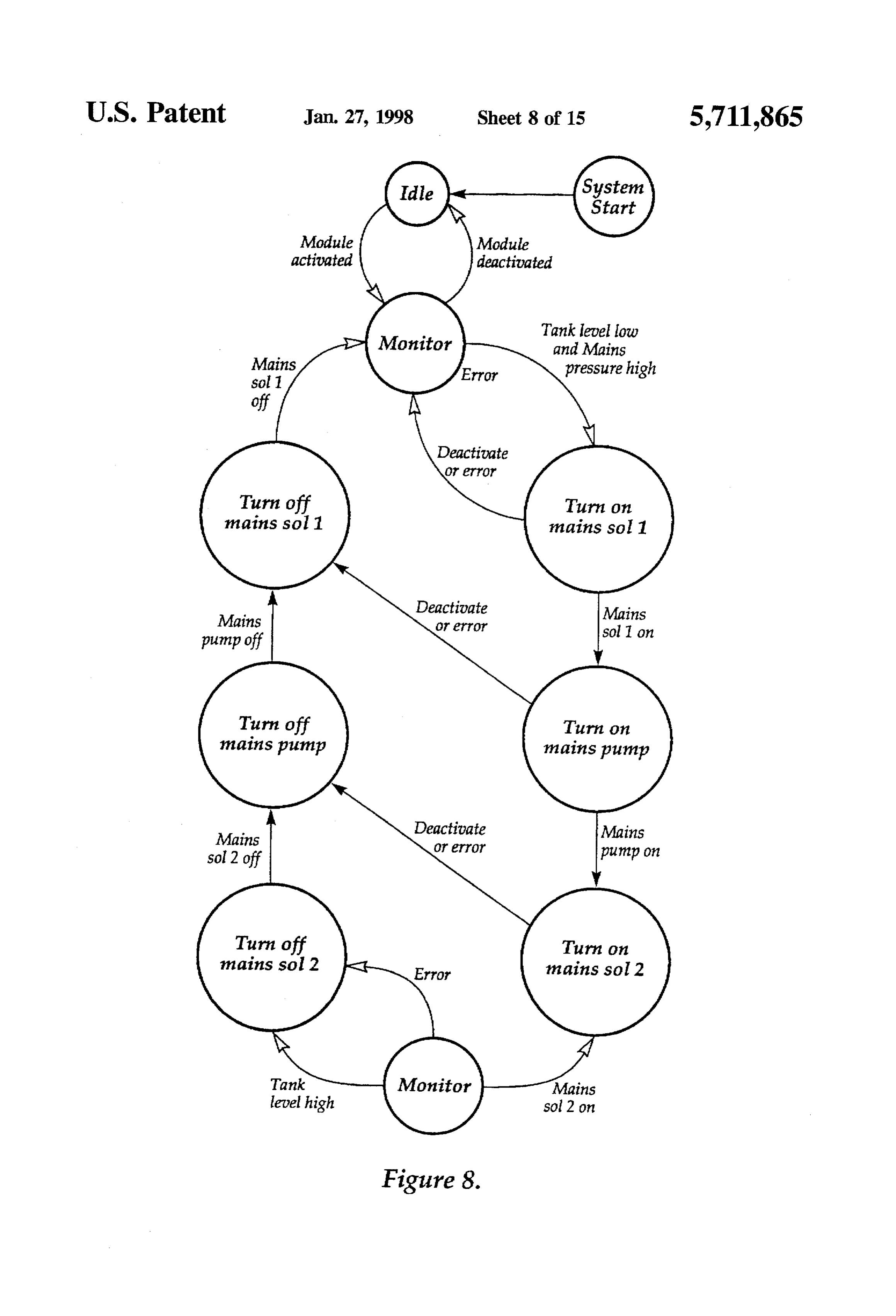
deactivated
Module activated
An active
Turn on Error Turn off water SOL 1 Uater SOL 1
Water SOL 1 Error Water O pump off
Turn on All cells full Turn off water pump pump
E orpressure
Check cell level and pressure
Cell level low Error
Turn on cell SOL
pressure high
Figure 9.
Page 11
Drawing sheet — no readable text.
Page 12
Drawing sheet — no readable text.
Page 13
Drawing sheet — no readable text.
Page 14
Drawing sheet — no readable text.
Page 15
Drawing sheet — no readable text.
Page 16
Drawing sheet — no readable text.
Page 17
ELECTROLYTC GAS PRODUCER METHOD The electrodes are preferably supported rigidly within the AND APPARATUS housing such that distortion and shorting in use may be minimised. For example, the electrodes may be mounted in
This invention relates to electrolytic producer apparatus. electrode frames which support the electrodes. The mount This invention has particular but not exclusive applica ing frames may provide for setting the interelectrode dis tion to electrolytic producer apparatus for producing mixed tance by being adapted to engage locating means associated hydrogen and oxygen gases from water for use as a fuel or with housing. For example the housing may be provided feedstock, and for illustrative purposes reference will be with grooves or the like adapted to receive the frame edges, made to such application. However, it is to be understood the frame and electrode assemblies being retained therein by that this invention could be used in other applications, such 10 a top cover member of the housing.
as producing oxygen and hydrogen mixtures for technical Preferably, however, the electrodes comprise a plurality and/or analytical use, and other electrolytic processes having of electrode assemblies of alternating polarity and compris a gas output.
The use of electrolysis for the production of hydrogen ing the preferred stainless steel mesh electrode bodies con figured with insulative frame portions such that the elec and oxygen gases is well known. In general, such apparatus have comprised an electrolytic cell including an anode and 15 trodes may be stacked in close parallel configuration to form a pack of electrodes which may be retained by close con cathode immersed in an electrolyte solution comprising a formation dilute aqueous solution of a mineral acid. The apparatus frame maywith also the interior of the housing. The electrode include conductive portions adapted to beer have generally been operated by the application of direct on corresponding insulative portions of the adjacent elec current of voltage sufficient to effect electrolysis water. The produced gases have generally been kept separate by means 20 trode frames to provide for mounting of a conductive pole, of a cell divider dividing the head space of the cell, and whereby the conductive poles of like electrodes may be generally including level control means or the like, such that bussed together for connection to one pole or the other of a explosive oxygen/hydrogen mixtures are substantially mini supply of direct current.
mized in the output streams. Certain apparatus utilizes a salt Preferably the separation between the plates in the cellis bridge connecting two separate half cells. 25 closely controlled to ensure consistency of production across The prior art apparatus suffer from several disadvan the cell. In aqueous acid electrolysis systems, such as those tages. The separation of the gases is rarely efficient that the utilizing electrolytes of deionized waterlihydrochloric acid of rise of explosion is eliminated. Backpressure differential concentration of about 2.4x10M, spacing of about 4 mm between the cell halves may result in electrolyte being between the electrode surfaces provides for economic cur displaced to the point where the gases mix without inhibi 30 rent densities to be used, in terms of providing high output tion. Additionally, plain electrode surfaces of such apparatus per unit volume of apparatus.
are subject to ionic polarization requiring the application of The use of spacings much less than 4 mm results in an overpotential to continue electrolysis. problems with heat dissipation with the attendant risk of The present invention aims to substantially alleviate the distortion and shorting of the electrodes. Surprising by, the above disadvantages and to provide electrolytic producer 35 use of much greater spacings than 4mm results in a dramatic apparatus which will be reliable and efficient in use. Other decrease in efficiency of the apparatus in terms of the objects and advantages of this invention will hereinafter amount of produced gas at standard temperature and pres become apparent. sure being produced for a given quantity of electrical power With the foregoing and other objects in view, this inven consumed. It is theorized that the gas evolution and flow tion in one aspect resides broadly in gas production appa upward through the electrolyte whilst constrained between ratus including: the electrodes has an advantageous effect on the reactive a housing containing an electrolyte; surface of the electrodes. For example, it may be that a electrodes at potential difference sufficient co cause elec polarized layer at an electrode which provides resistance to trolysis of said electrolyte to form a gas; the passage of current and thus dissipates energy as heat may supply means adapted to maintain said electrolyte, and 45 be disrupted by turbulence caused by the gas entrained in the collection means for gases produced by said to electroly relatively narrow interellectrode space. Constrainment of SS. convective movement in the electrolyte may also contribute The apparatus is preferably for the production of hydro to this phenomenon. The electrodes are preferably supported gen and oxygen gases from water and to this end the clear of the bottom of the housing such that the electrolyte electrolyte is preferably comprises an dilute aqueous solu 50 bay circulate to maintain substantial consistency of compo tion of a mineral acid catalyst selected from the hydrogen sition throughout the housing and to provided for improved halide acids, sulphuric or nitric acids. Preferably, the catalyst dispersion of any locally evolved heat. comprises hydrochloric acid. Accordingly, in a further aspect this invention resides The housing may be of any suitable material resistant to broadly in apparatus for gas production including: the electrolyte. Preferably, the housing is of an insulating 55 a housing containing an electrolyte, and material to prevent losses due to conduction through the a plurality of substantially planar electrodes disposed in housing such as impedance and hysteresis losses. The hous substantially parallel spaced relation in said electrolyte, ing is preferably substantially sealed with the entry of alternate ones of the electrodes being connected to maintenance water and exit of produced gases being via respective poles of a direct current supply of potential appropriately valved inlet and outlet apertures. The difference sufficient to cause electrolysis of said The electrodes may take any suitable form and are pref electrolyte, wherein the inter electrode distance is erably non sacrificial under expected electrolytic conditions. selected whereby produced gases are constrained by For example, the electrodes may comprise an inert conduc adjacent electrodes to cause turbulence in said electro tive substrate such as noble metal, graphite or stainless steel, lyte at the respective electrode planar surfaces. with or without a surface activating catalyst. Preferably, the 65 The supply means may take any suitable form consistent electrodes comprise stainless steel mesh material having a with the function of maintaining the electrolyte as it is coating of platinum black deposited thereon. consumed by the electrolytic process and will be determined
Page 18
from the gas to be produced. In the preferred hydrogen/ Preferably, the control means for the power supply forms oxygen producing apparatus, the supply means is a water a logical or physical part of an integrated control portion of supply. the apparatus, adapted to control electrolyte parameters of The water supply means may take any suitable form such such as level, composition and temperature, power charac as pressurized supply from mains (reticulated) water supply teristics such as voltage and current, and conditions at the of from a treated water feedstock if this is appropriate. The outputside of the apparatus downstream of the housing such water component of the electrolyte is preferably purified as gas delivery pressure and temperature. Preferably, the water prepared by one or more offiltration, reverse osmosis, control portion comprises programmable logic control distillation or deionization. In order to reduce particulate means to control all aspects which may be so controlled. For contamination of the water feed, the supply is preferably O example, current/voltage regimes for each cell assembly fitted with a submicron filter. may be at least in part controlled by the programmable logic Where the water supply contains trace impurities such as control means in response to sensor inputs such as a tem dissolved salts, the apparatus may be configured to periodi perature sensor, a back pressure sensor or like sensors cally reverse the direction of current flow between the associated with each cell assembly.
electrodes, thereby disrupting deposition of depositable salts on the electrodes. Any precipitated impurities may fall to the 15 byPreferably, the the output of the apparatus is also monitored controller means. For example, an operator may wish bottom of the housing, which may be provided with drain to query the controller means in terms of gas volume means such that the impurities may be periodically purged and the housing may be drained for maintenance. production, relative efficiency, temperature, pressure or any Preferably the water supply includes control means other chemical or physical quantity including chemical responsive to electrolyte level and/or acid concentration. For 20 composition. This data may also be utilized as primary example, the water supply may be controlled by control control data for operation of the apparatus via the controller. means such as a float controlled valve means, electronic Apparatus for electrolysis of acidified water produces an level sensing means operable to switch a valve by means of explosive mixture of hydrogen and oxygen in substantially a solenoid or other electromechanical actuator, or the like. stoichiometric proportions, which mixtures are explosive Alternatively, the control means may include gravimetric pH 25 both in isolation and in admixture with air over a relatively sensing sensor means. Preferably, the water is admitted to wide range of compositions. Accordingly, the apparatus is the bottom of the housing. preferably provided with means adapted to prevent or ame Preferably, the water feed is supplied To an intermediate liorate the effect of ignition of the gas mixtures. For tank prior to admission to the housing, the intermediate tank example, the apparatus may be configured and controlled being configured as a water trap for gas output from the 30 such that dead spaces which may accumulate gas in the apparatus. By this means, any acid containing electrolyte housing or downstream thereof may be minimized by design entrained in the produced gas is stripped by the feed water and/or control.
in the intermediate tank to be cycled back to the housing. Further, the gas flow path downstream of the housing may The collection means preferably takes the form of a top be provided with passive control means such as flashback portion of the housing including an aperture such that gases 35 arrestor means. For example, the gas path may include one rising to the top of the housing may be collected member of or more flashback arresters comprising an arrestor housing the preferred electrode assemblies and be conveyed from the having a gas inlet and a gas outlet and being packed with a housing thereby. Preferably, the aperture includes or leads to thermally massive porous material such as stainless steel separator means adapted to return at least some any elec wool. The arrestor housing may be partially filled with water trolyte mist entrained in the gas flow back to the housing. and the gas inlet led by conduit to a point below the surface For example, the aperture may include or pass a separator of the water. The gas outlet may collect from a minimized comprising a passage so shaped and configured as to encour gas space above the water.
age collection of entrained electrolyte such that returns by In use, a flashback condition from upstream of the flash gravity to the cell. back arrestor will be extinguished at the inlet beneath the An example of such apparatus includes a blind sleeve 45 surface of the arrestor water. A flashbackfrom the upstream having a hollow conical collection member disposed on side will be diffused into the stainless steel wool and blind end thereof, the apex of the conical collection member extinguished by reduction of the flame front to a temperature being directed substantially upstream of the gas flow, the below the activation temperature of the gas mixture. conical surface having one or more delivery openings there In addition to passive systems, there may be provided through disposed away from the apex and providing a 50 flashback arrestor means including sensor means adapted passage for gas downstream of the separator. Produced gas sense a flashback condition and to be read by the preferred having entrained electrolyte impinges on the sleeve wall and programmable logic controller which may then in turn end, and the conical surface whereupon a substantial part the operate appropriately to remove the flashback condition. For entrained electrolyte is deposited to run down the sleeve and example here may be provided sensors monitoring one or conical surface and drip back into the housing. 55 more of shock, temperature or infrared or ultraviolet radia The apparatus may comprise a plurality of housing por tion in a gas flow path and the sensing of a flash back tions each with its own supply, electrodes and collection condition being interpreted by the controller, whereupon the means each comprising a cell assembly of the apparatus. gas flow may be interrupted or diminished by one or more The apparatus is preferably driven by power supply of high speed valve means, current interrupting means or the means which is subject to control means responsive to one like. The response to flashback being sensed may also or more conditions of the apparatus. Where multiple cell include shutting down of non critical components such as assemblies are used, it is preferred that each be provided pumps and the like to shut down all functions of the with its own controlled power supply whereby individual apparatus pending resolution of the flashback causing con power characteristics of the cell assemblies may be accom dition.
modated and to promote reliable operation, and to permit 65 The flashback arrestor may include a relatively thin, long varying process conditions in each cell as necessary or but low volume path for the gas having a sensor and fast desirable. valve at opposed ends thereof, whereby the propagating
Page 19
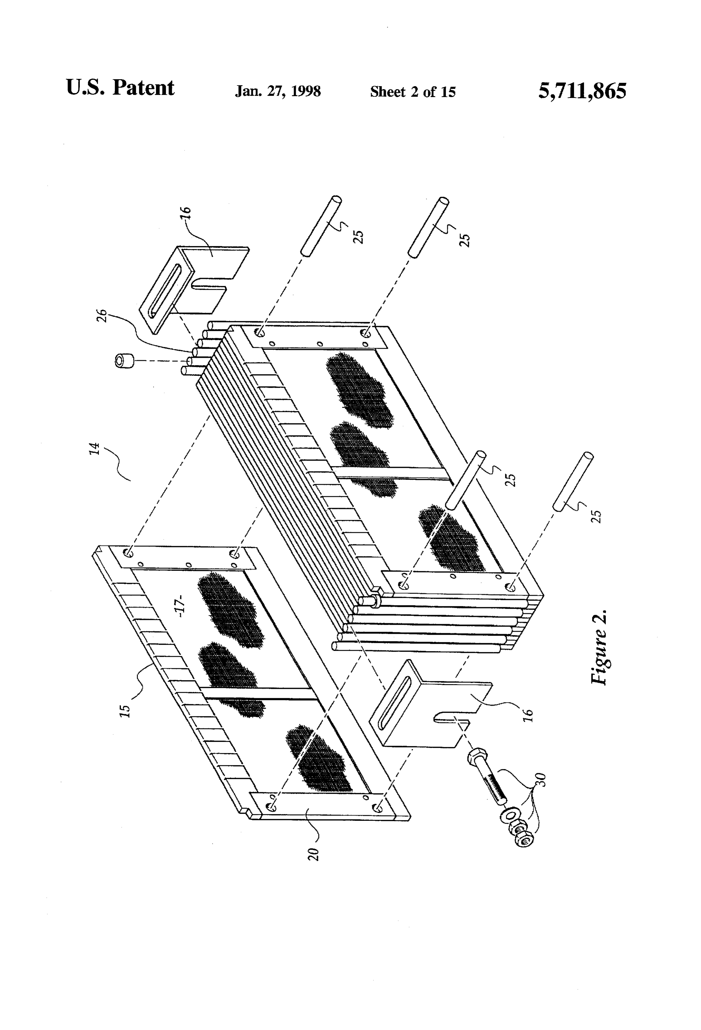
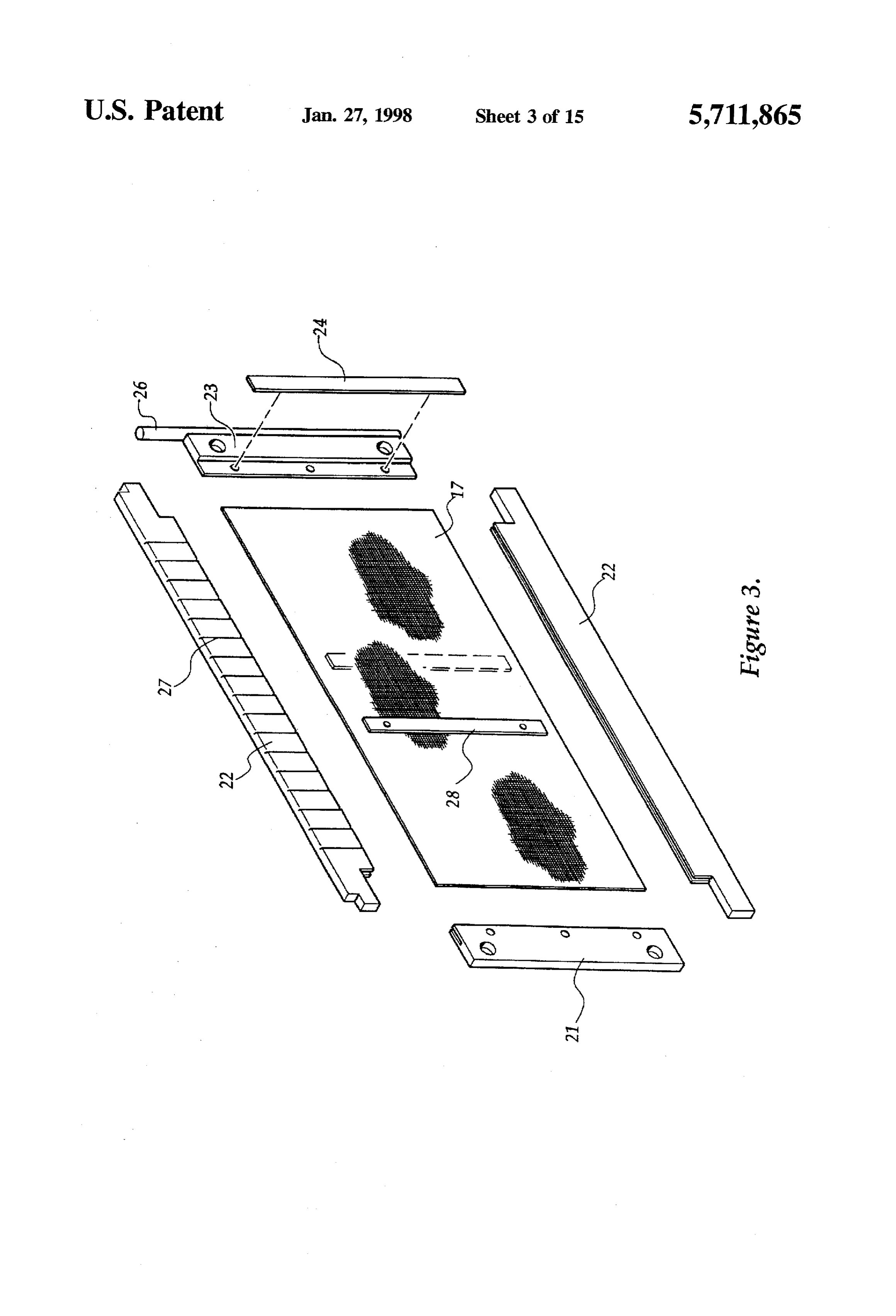
flashback condition at the sensor triggers the closure of the an insulative end member 21 and rap and bottom members valve. Sensors and valves may he paired at either end of the 22 of an acid resistant P.V.C. and a 316 stainless steel tube to detect and respond to a flashback condition propa terminal assembly 23. The plate housing 20 acts as both a gated from either end of the tube. support for the body portion 17 as well as a spacer and The end use to which the produced mixture of hydrogen insulator between each of the electrodes 15 within the cell, and oxygen may be put includes as a feedstock for separa being slotted in the case of the PVC components to receive tion apparatus, a fuel for fuel cells of heat engines or for the mesh portion 17 and provided with a clamping member analytical processes and especially calorimetric analysis, 24 for optimising electrical integrity of the terminal assem welding or cutting of materials or the like.
In one embodiment it is envisaged that the gas may be 10 blyThe23 with the mesh 17.
electrodes 15 are alternated with the terminal assem produced on demand and metered into a heat engine such as bly of an electrode bearing on the insulating end members 21 an internal combustion engine where it may be used in of the adjacent electrodes 15. The physical and electrical admixture with air or as substantially the whole of inducted integrity of the electrode assembly 14 is provided by stain charge. Since it is desirable to produce the has on demand as less steel shorting pins 25. The terminal assemblies 23 each opposed to storing the gas, the internal combustion engine 15 include a threaded stainless steel terminal post and respec may be provided with generating means adapted supply tive terminal posts are made electrically common by the pole electrical energy to the power supply means of apparatus. plate 16 adapted to receive a conductive stud 30 which Accordingly, the gas output may be connected to an passes out through the housing 11 and provides an external internal combustion engine adapted to perform useful work electrical connection point for each set of electrodes 15 in a and the engine may also be connected to power generation 20 means for generating electricity for the power supply means particular electrode assembly 14. The upper members 22 of the plate housings 20 are provided with vertical grooves 27 of the apparatus. By this means an engine which may be adapted to allow the passage of generated gas into the required do mechanical work may utilize excess power to headspace of the chambers 13. The mesh portions 17 are also generate a power supply for the apparatus.
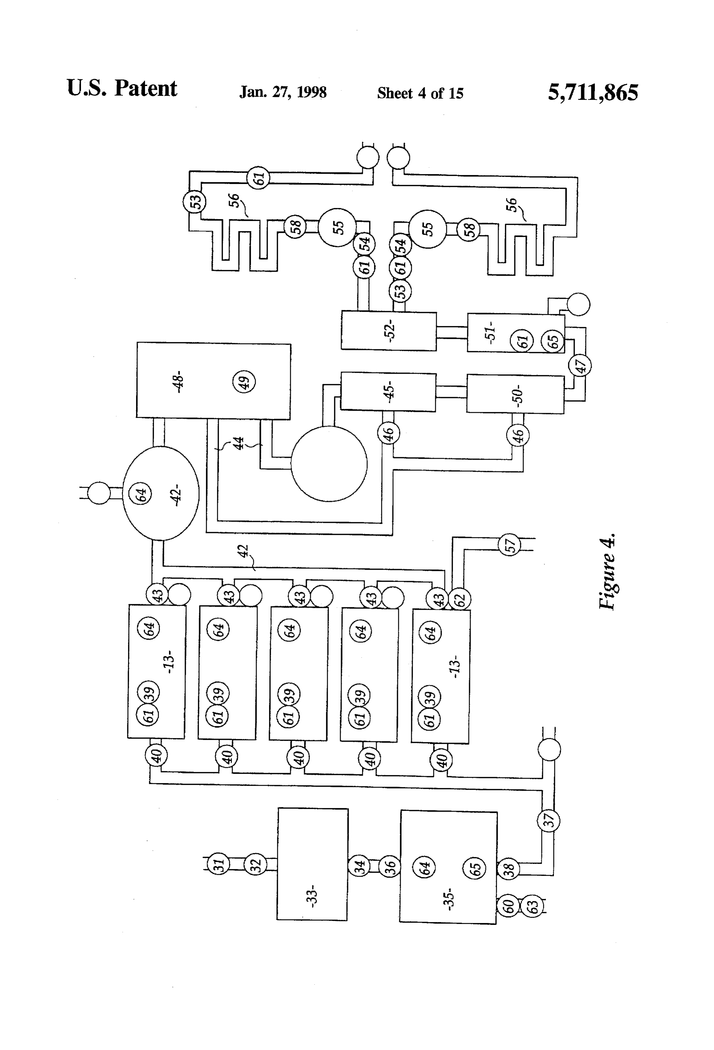
In a yet further aspect, this invention resides broadly in a 25 stiffened by insulative stiffeners 28. The flow path of liquids and gases are illustrated dia method of producing mixed hydrogen and oxygen compris grammatically in FIG. 4, wherein distilled water supply ing the steps of:
providing gas production apparatus comprising a housing solenoid valve 32theunder supplies water to apparatus via a pressure sensor 31 and microprocessor control through a containing acidified water electrolyte and a plurality of primary stainless steel filter 33 that removes particulate substantially planar electrodes disposed in substantially 30 impurities down to 0.3 of a micron. When the solenoid valve parallel spaced relation in said electrolyte, the inter 32 is opened, water is drawn through a 24 volt pump 34, electrode distance being selected whereby produced which is also controlled by the microprocessor, and thence gases are constrained by adjacent electrodes to cause to a reservoir 35 of thirty-litre capacity via a further solenoid turbulence in said electrolyte at the respective electrode valve 36. The reservoir 35 is constructed of 316 grade planar surfaces; 35 Stainless Steel and is provided with internal baffles to connecting alternate ones of the electrodes to respective control Surge.
poles of a direct current supply of potential difference The cell chambers 13 are maintained at a selected elec sufficient to cause electrolysis of said electrolyte; trolyte level by means of a supply pump 37 controlled by collecting generated gas from the top of said housing, and solenoid valve 38 and delivering to each cell via a bank supplying make-up water to said housing to replace that O manifolded solenoid valves 40, each being under the control electrolysed to gas. of a level sensor 39 as well as being under master control of In order that this invention may be more easily understood the microprocessor which monitors levels within the cell and put into practical effect, reference will now be made to chambers 13.
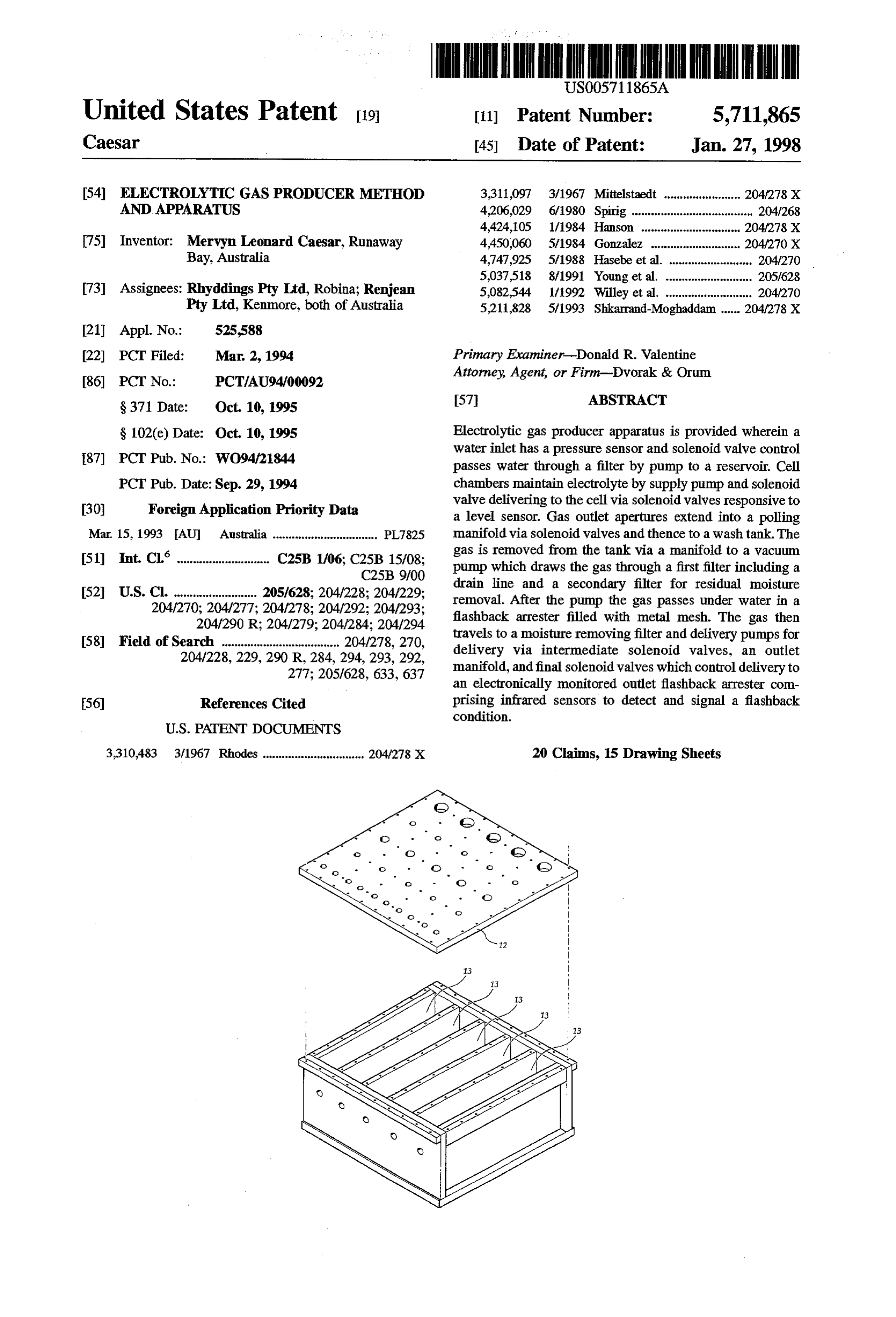
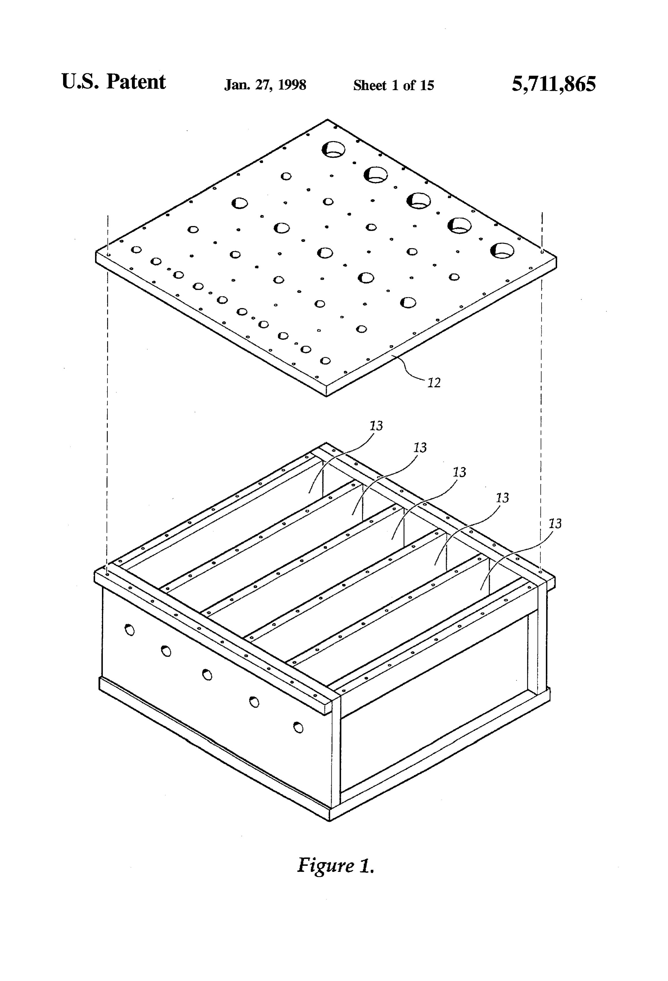
the accompanying drawings which illustrate a preferred The housing cover 12 is provided with gas outlet aper embodiment of the invention, wherein: 45 tures 41 which extend from the inside of the cell chamber FIG. 1 is an exploded to perspective view of apparatus in upwards to a collection line by means of an inverted conical accordance with the present invention; chamber which causes liberated gases to swirl therethrough. FIG. 2 is a top perspective view of an electrode for use in This results in entrained droplets being substantially the housing of FIG. 1; deposited on the conical walls whereupon the droplets are FIG. 3 is top perspective exploded view of a single 50 returned to the cell under gravity. The gas outlets from each electrode of the array of FIG. 2; of the five cell, passes into a pooling manifold 42 via FIG. 4 is a flow diagram through apparatus in accordance individual solenoid valves 43. From the manifold 42, the gas with the present invention; is then fed to a wash tank 48 providing a headspace of gas FIGS. 5 to 9 illustrate diagrammatically the logic control therein. By taking the gas through pipes to the bottom of the systems of the apparatus of FIG. 4, and 55 wash tank 48 the gas is water scrubbed which provides for FIGS. 10 to 15 illustrate diagrammatically the function both a flashback arrest and removal of entrained electrolyte. features of the present apparatus and method. The gas is removed from the water tank via a stainless steel With reference to the figures there is provided electrolytic manifold 44 including a back pressure controller 49 under gas producer apparatus 10 including a housing and housing microprocessor control. From the twin outlets of the mani cover 12, the housing 11 being divided into five cell mount fold 44 the gas is passed to a double headed vacuum pump ing chambers 13. Each cell mounting chamber 13 includes 47 which draws the gas through a first filter 45 including a in electrode assembly 14 comprised of thirteen electrodes 15 drain line adapted to return liquid contaminants, mostly each, the electrodes alternating in the assembly between water, to the wash tank 48 via valve 46, and a secondary being connected to one or the other of a pair of poles 16. filter 50 of the Cunotype for residual moisture removal. This Each of the electrodes comprises a 316 grade stainless 65 removes moisture to 0.3 of a micron. After she pump 47 the steel mesh body portion 17 which has been coated with gas passes into a flashback arrester 51 filled with woven 316 platinum black and mounted in a plate housing 20 including Stainless mesh and 25 cm of water. The gas enters the
Page 20
flashback arrester under the water level. The gas then travels primary AC voltage and current transformer 87 having in two lines to a moisture removing filter 52 of the Cuno output 90 to readout instrumentation monitoring AC supply type, whereafter it enters delivery pumps 53 which pres and transformer output. Raw AC subvoltage power is fed surises the gas to 36 psi for delivery via intermediate through a main switch 91 to variac 92 to staged secondary solenoid valves 54, an outlet manifold 55 having a pressure AC voltage and Current transformer 93 and tertiary voltage regulatory function, and final solenoid valves 58 which transformer 94 connected to a selenium rectifier 95 to control delivery to an electronically monitored outlet flash provide DC current to drive the cell assembly. back arrester 56. The outlet flashback arrester contains two The rectifier 95 output provides input for a DC voltage infrared sensors to detect and signal aflashback condition to and current transformer 96 connected via output terminals the microprocessor for safety. In the event of a flashback, the 10 97 to the cell assembly electrodes. Cell assembly current infrared sensors detect a change in heat coming back up the draw and operating voltage is monitored and controlled by tube. This change activates a solenoid to cut-off the gas flow. monitor module 100 responsive to and providing input to The input power to the apparatus is microprocessor select power controller 101, the monitor module 100 and power able to accept 240, 110.32, 24, 12 volts. The output voltage controller 101 being mutually connected to the main con is variable up to 7.5V with a current rating up to 1000 amps. 15 troller boards 70 by SCI interface 102. The power controller Typically the apparatus utilizes power at 7.5 volts ACRMS 101 provides data on power consumption and zero crossover at 30 amps for the electrolytic process. detection from the transformers 87,93 as well as responding The apparatus is also provided with pump out facility for to input from safety override command interface 103 iso the cells (pumps 57 and solenoids 62) and the reservoir lated from the data interface 102.
(pump 60 and solenoid 63). and the monitoring process The power controller also provides mains isolation includes a plurality of pressure sensors 61 and temperature 20 switching of the mains switch 91, switching at the cell sensors 64 monitoring the pressure and where appropriate assembly by control of the monitor module 100 and over temperature in the cell chambers 13, the reservoir 35, the load protection. An emergency override switch 104 couples manifold 42 the outlet delivery pumps 53, as well as level to the safety override interface 103 to provide manual master sensor 65 in the reservoir 35 and the water trapping filter 51. shutFIGS. down control for the cell power control assembly. 12, 13 and 14 illustrate diagrammatically the
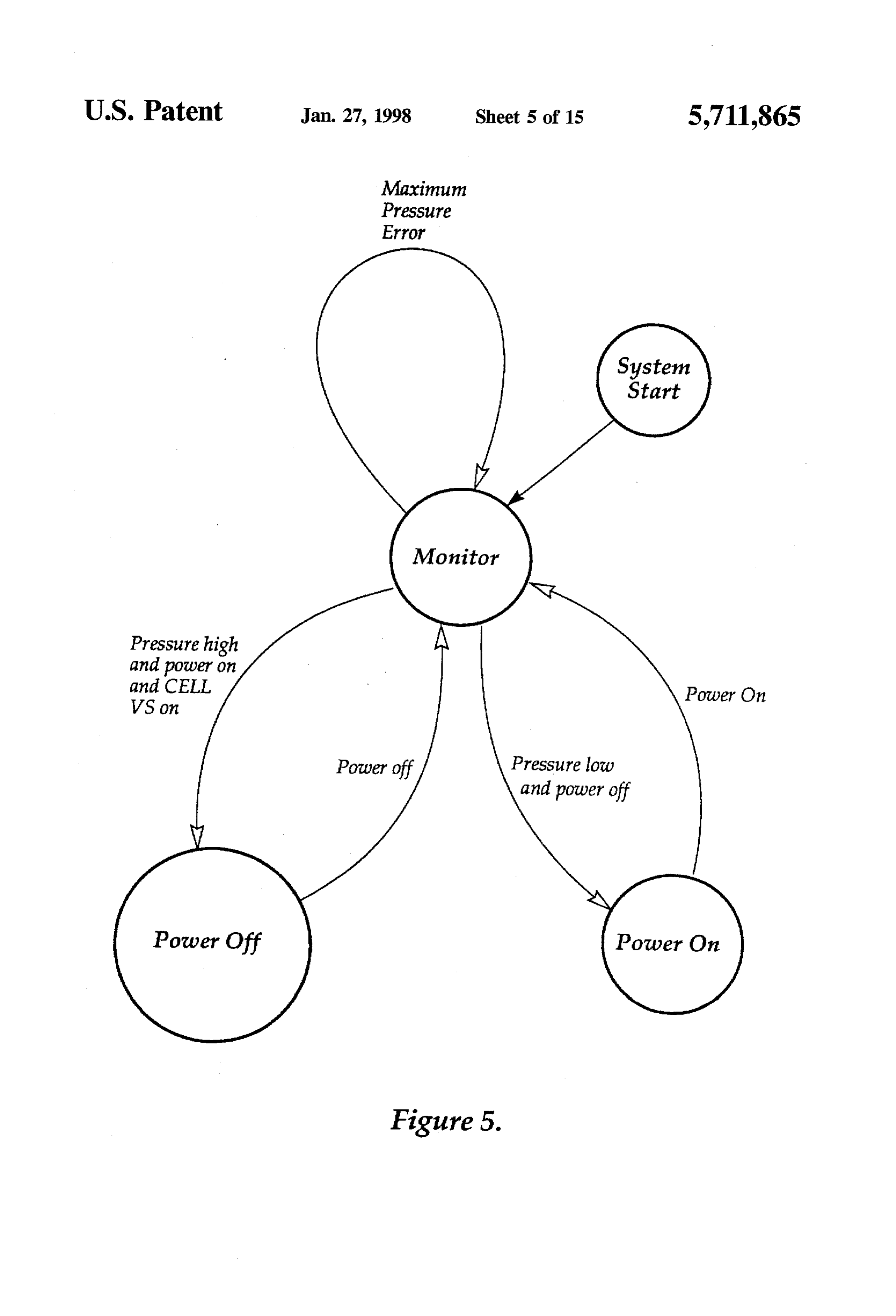
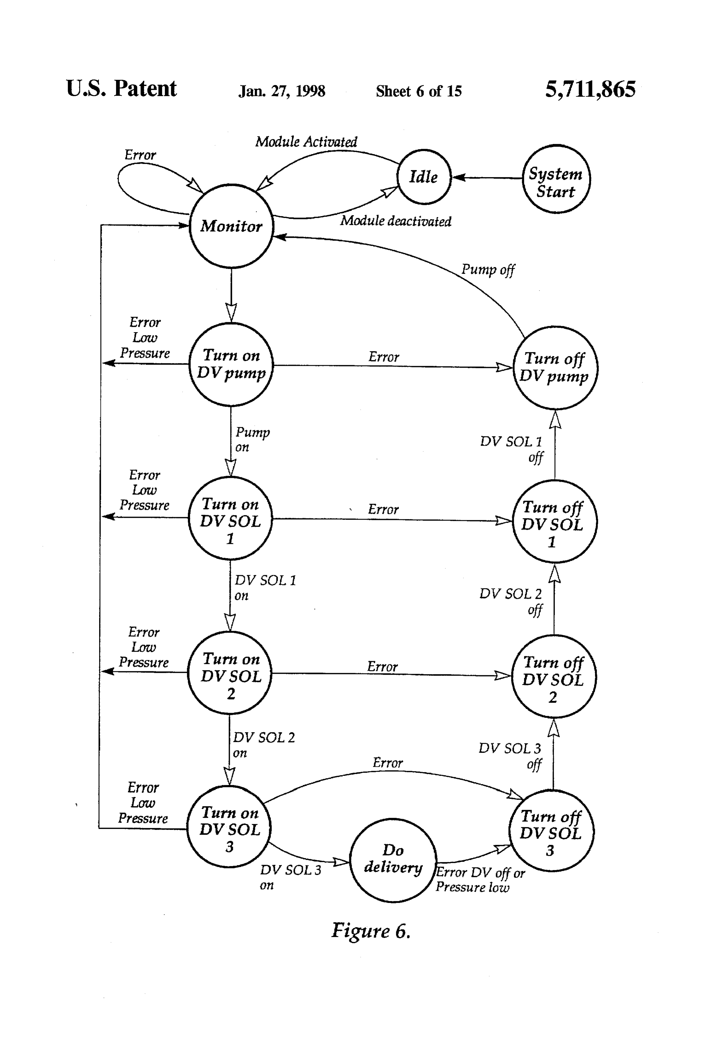
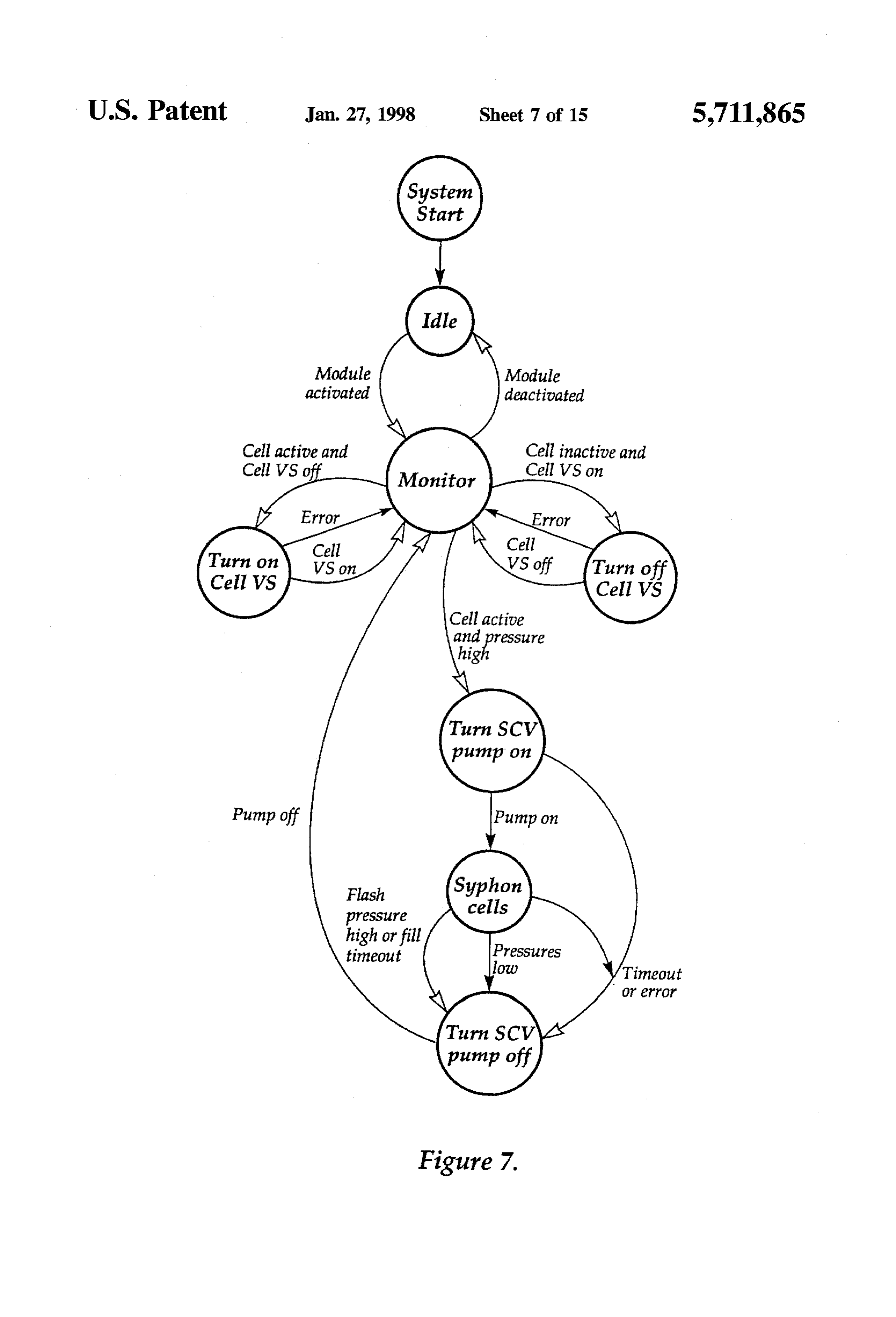
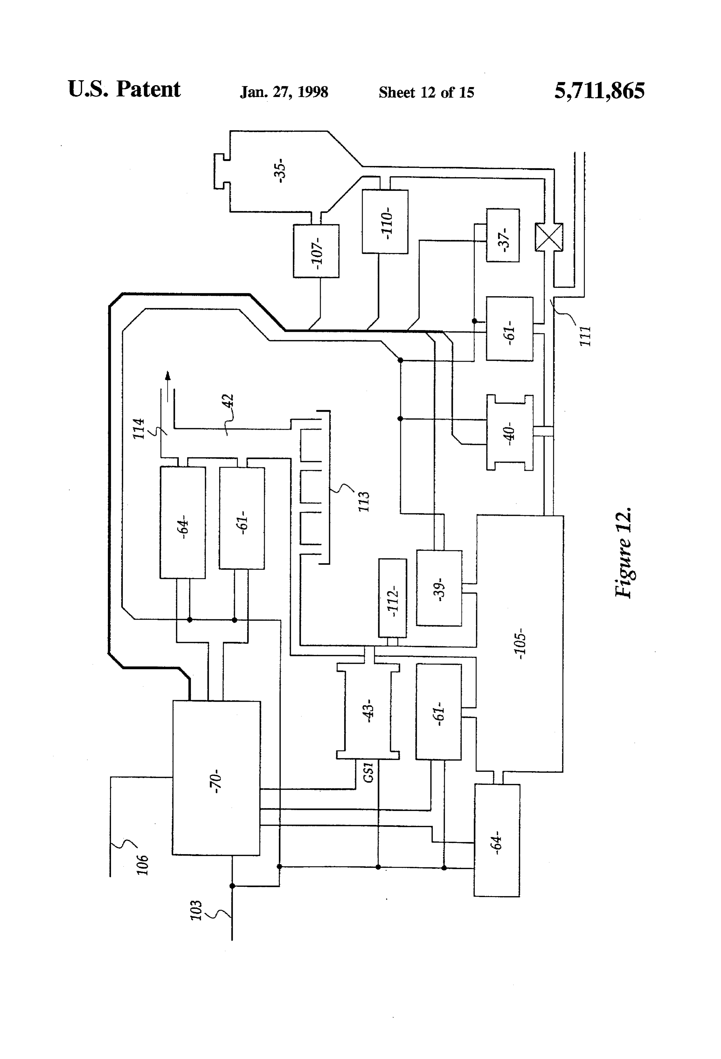
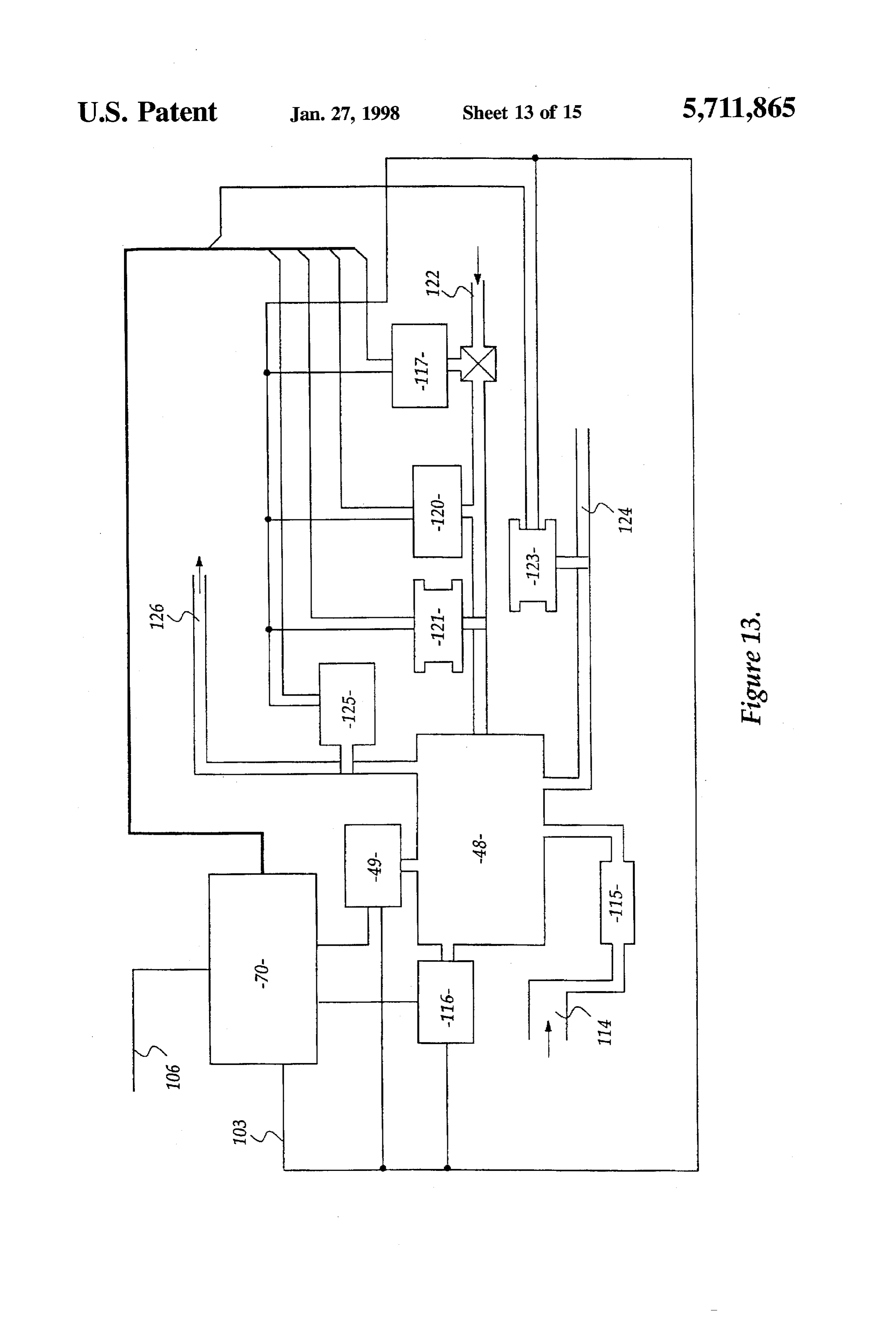
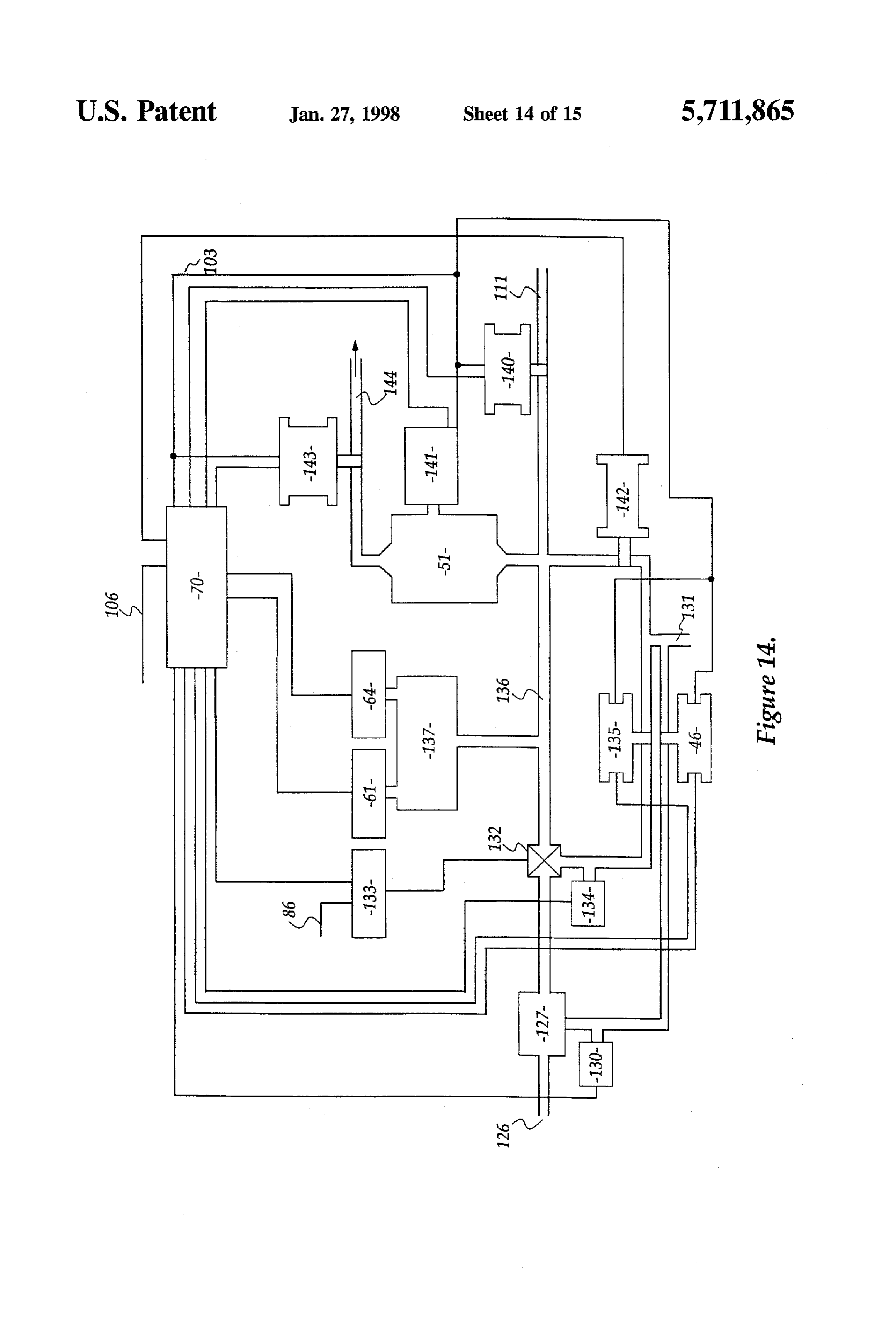
In the FIGS. 5 to 9 these represent the control logic path 25 principal functional gas and water operating features under for the power supply, gas delivery, cell gas clearance, the control of the main controller boards 70, illustrated with reservoir top up and cell top up processes respectively. In reference to a single board these figures, descriptive matter is included as required for clarity. The operator controlandterminalsingle cell assembly 105 for RS-422 interface 106 explanation of the processes and wherein the term CELLVS and safety override interfaces 103 are as described above. refers to the cell vapour solenoid valve, DV pump refers the 30
The water reservoir 35 is equipped with a low-water gas delivery pump, DVSOL1 and 2 refer to the first, second sensor 107 and a no-water sensor 110 providing data to the end third gas delivery solenoid valves respectively, SCV main controller board 70 on rank status. The supply pump 37 pump refers to the pump delivering the gas from the cell delivers water to both the cell assembly 105 and flashback headspace, mains sol 1 and 2 refer to the solenoid valves 32 arrester 51 via delivery manifold 111. Delivery pressure in and 36 of FIG. 4, water SOL 1 refers to the solenoid valve 35 the manifold 111 is monitored by the main controller board 38 of the apparatus of FIG. 4 and cell SOL refers re the 70 via water pressure sensor 61.
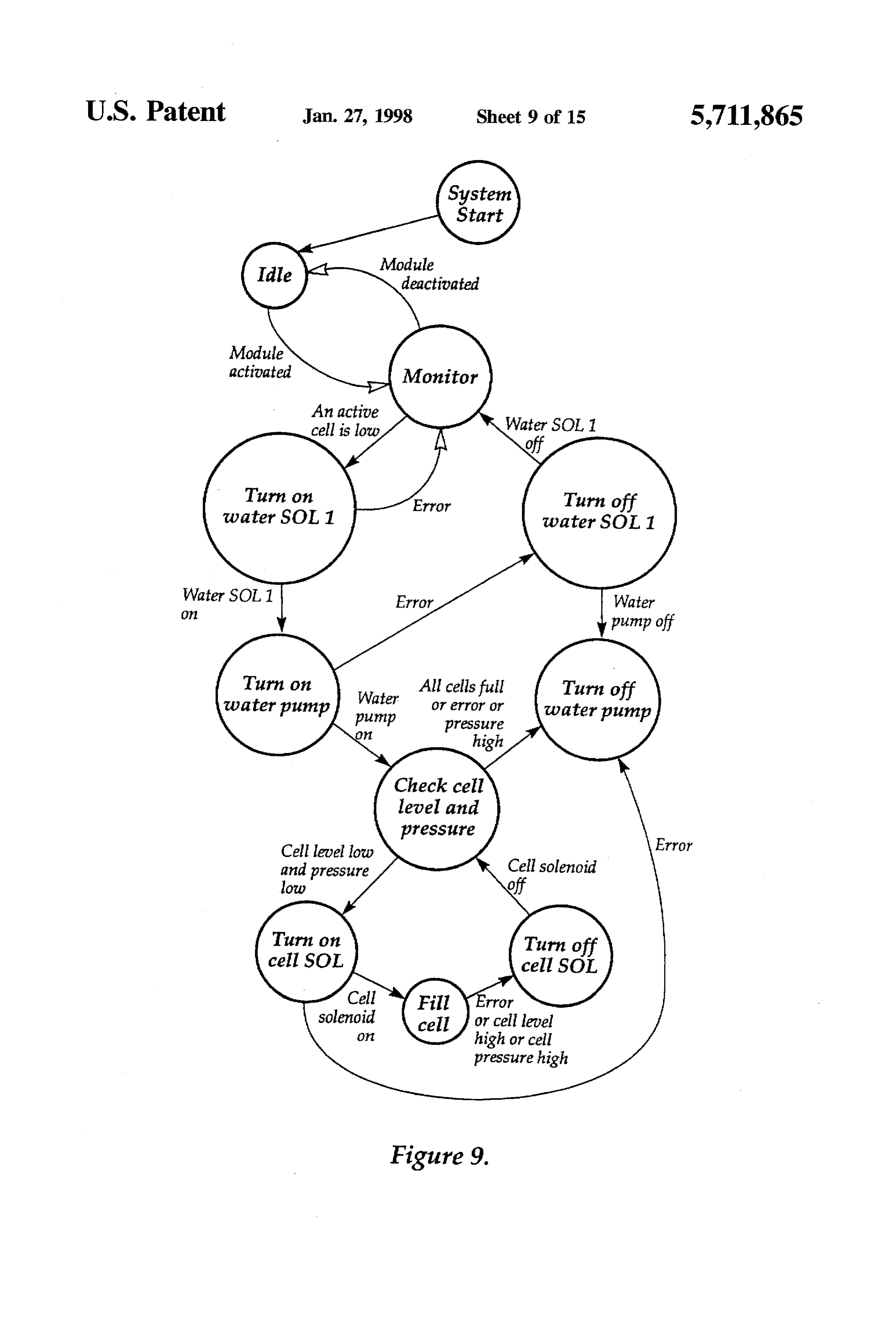
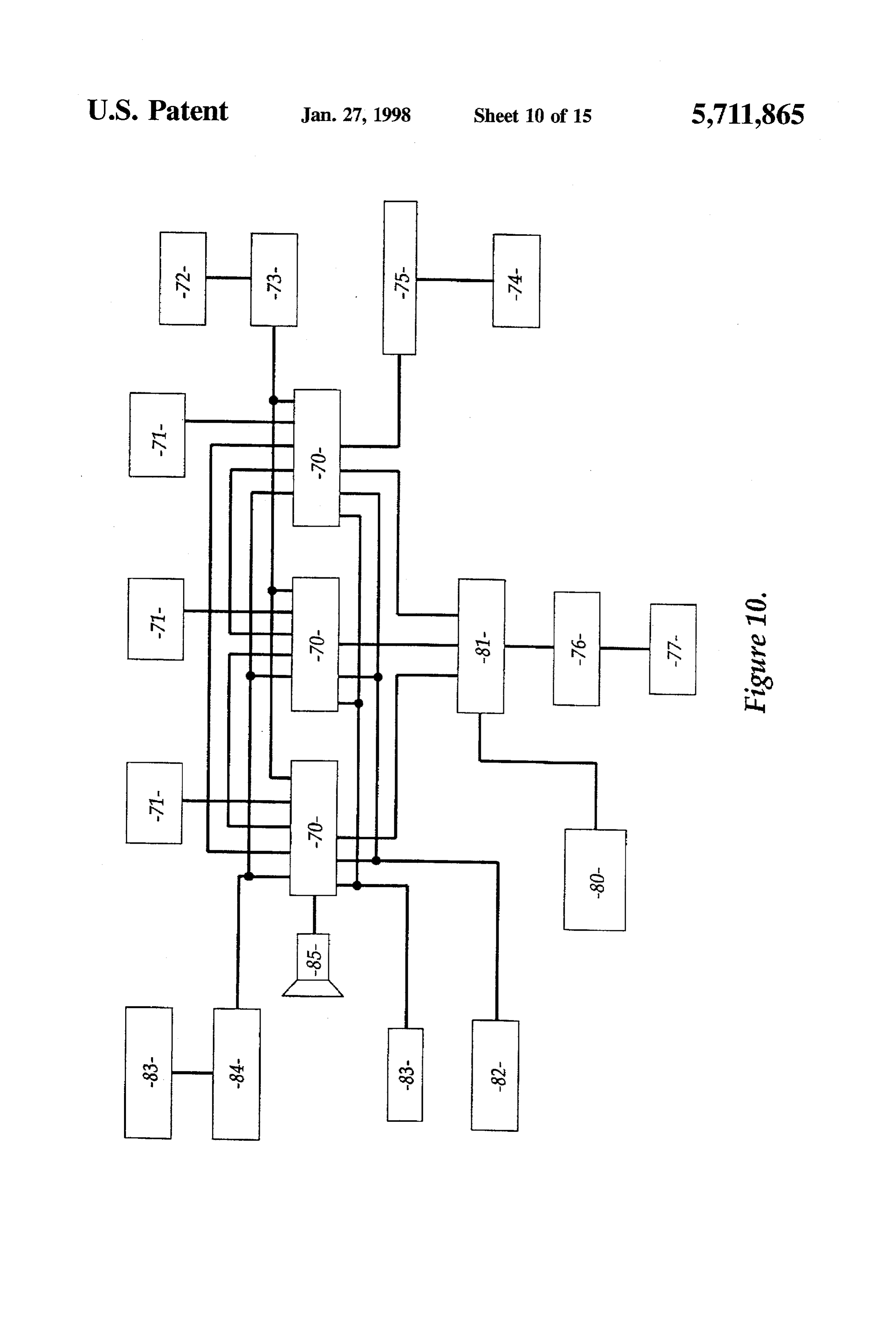
solenoid valve 40 of each cell. The cell assembly 105 includes an electrolyte level sensor The functional diagrammatic description illustrated in 39 providing control input for the main controller board to FIGS. 10 to 15 illustrate the functional features of apparatus operate the water inlet solenoid valve 40 and thence main and ancillary apparatus. tain electrolyte levels. The cell assembly is also equipped FIG. 10 illustrates a preferred control arrangement with a pressure sensor 61 of 100-200 kPa range and K wherein three independent microprocessor control boards 70 thermocouple temperature sensor 64 of 0°-100° C. range. provide master control redundancy and are networked via a Each of the temperature 64, delivery and cell pressure 61 TOKEN-RINGTM network and connect with an operator sensors, the supply solenoid 40 and pump 37 are connected control terminal (not shown) by an RS-422 protocol inter 45 to both the control board 70 and the safety override interface face. Each microprocessor control board 70 is powered by 103.
its own power 24 VDC power supply 71, and the three Gas produced by electrolysis passes from the cell assem power supplies 71 are backed up dynamically by a backup bly 105 via a metering orifice 112 and gas control solenoid battery 72 controlled and charged by battery controller 73. valve 43 to a gas manifold 42 where the flow combines with Mains AC current operated devices such as a final deliver 50 that from the other cell assembly outputs 113. The gas gas pump 74 are switched by The controller boards 70 via manifold 42 is equipped with its own pressure sensor 61 of mains current relay switch 75. Active DC powered devices 100-200 kParange and temperature sensor 64 of 0°-100° C. such as electronic flash back arrester at solenoids 76 and range which, with the gas control solenoid valve 43 are their optical sensors 77 as well as an emergency cut out connected to both the control board 70 and the safety switch array 80 are bussed to a 24VDC sub controller board 55 override interface 103.
81 responsive to and providing inputs for the main controller Gas passes from the gas manifold 42 via cutlet 114 to the boards 70. bottom of the water-containing gas wash tank 48 via a non Passive switch sensors such as pressure transducers 82 return valve 115, where the gas is water scrubbed to elimi and other solenoids 83 input directly to or are driven directly nate traces of electrolyte. The gas wash tankis provided with by the main controller boards 70. Scalar sensors such as a water level sensor 116 and back pressure sensor 49, the temperature sensors 83 are interpreted by an interface 84 and water level being interpreted by the main controllerboard 70 data transmitted to the main controller boards 70 by the to control water entry to the wash tank via water pump 117, communications protocol determined thereby. An audible pressure sensor 120 and solenoid valve 121 from a separate alarm 85 is driven by the main controller boards in response water supply 122. Each of the water level sensor 116, back to a fault condition. 65 pressure sensor 49, water pump 117, pressure sensor 120 and FIG. 11 describes power control for each of the cell solenoid valve 121 are also bussed to the safety override assemblies and includes an AC mains supply input 86 to a interface 103.
Page 21
The wash tank 48 may be periodically drained under electrodes at potential difference sufficient to cause elec control from the main controller board 70 via drain solenoid trolysis of said electrolyte to form a gas; 123 and drain 124 which may also provide for gas purge in a water supply means adapted to maintain said electrolyte; response to the safety override interface 103. Gas passes collection means for gases produced by said electrolysis, from the wash tank 48 via gas solenoid valve 125 and wherein said electrodes are mounted in electrode conduit 126 to the filter assembly 127 including water level sensor 130 operating under control to periodically purge frames which support the electrodes in the housing, accumulated wash tank water to a waste outlet 131 via said electrodes comprising a plurality of electrode solenoid valve assemblies of alternating polarity configured with insu From the filter assembly the gas passes to a gas pump 132, 10 lative said frames such that the electrodes may be mains 86 powered by switch 133 and being of one water trap stacked in close parallel configuration, and wherein type having its own water level sensor 134 and solenoid said electrodes comprise a substantially inert material valve 135 to the waste outlet131. Gas delivered by the pump selected from the group consisting of a noble metal, a 132 passes to the flashback arrester 51 via conduit 136, the graphite metal, a stainless steel, the stainless steel being output of the pump being buffered by a gas reservoir 137 15 formed of a steel mesh material having a coating of disposed in the conduit 136. The gas reservoir 137 is platinum black deposited thereon, wherein said elec provided with a pressure sensor 61 of 100-200 kPa range trode frame includes a conductive portion adapted to and temperature sensor 64 of 0°-100° C. range. bear on a corresponding insulative portion of an adja Water supply to the flashback arrester at 51 via water cent electrode frame and providing a mounting for a manifold 111 is controlled by water inlet solenoid 140 conductive pole, whereby the conductive poles of like responsive to both the water level sensor 134 of the pump 20 electrodes may be bussed together for connection to 132 and a water level sensor 141 associated with the one of a positive and negative pole of a supply of direct flashback arrester, such that water levels may be maintained current.
in both by this means. The flashback arrester 51 is drained 2. Gas production apparatus according to claim 1, wherein by means of outlet solenoid 142 to waste outlet 131.
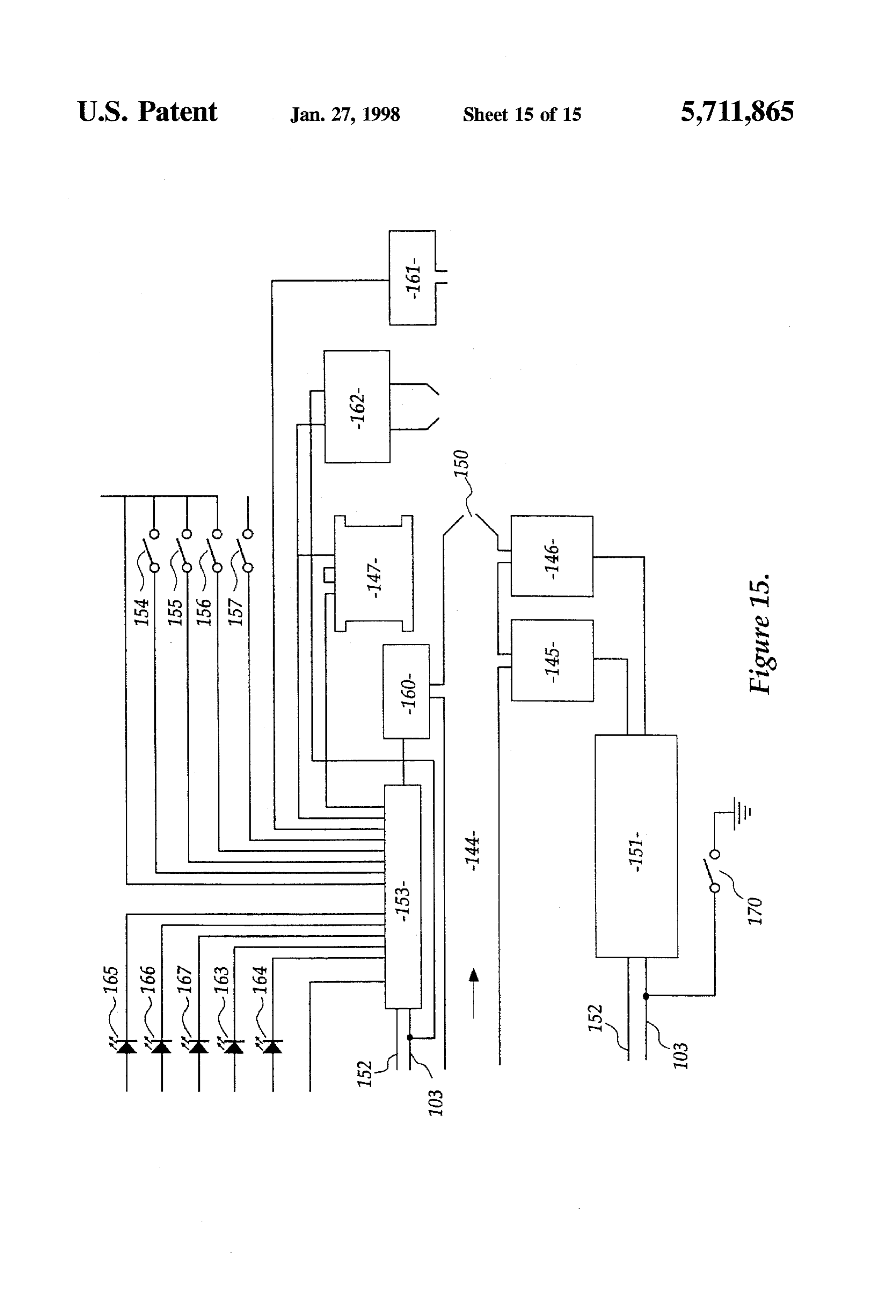
From the flashback arrester 51, gas passes to its end use, 25 said3. supply
Gas means is sealed with respect to said housing.
production apparatus according to claim.1, wherein for the purposes of description in this case a burner said electrolyte supply assembly, via a main gas solenoid valve 143 to gas conduit bination of a deionized means is adapted to furnish a com waterihydrochloric, acid of concen 144. The burner assembly includes the electronic flashback tration of about 2.4x10M.
arrester 56 of FIG. 4 which in this case comprises first 145 and second 146 infrared flashback sensors located up and 30 said4. Gas production apparatus according to claim.1, wherein supply means is adapted to furnish purified water of downstream respectively of a gas control solenoid valve 147 submicron filtration, reverse osmosis, distillation or deion in the conduit 144. The second flashback sensor is located ization.
just upstream of a burner let 150 terminating the conduit 5. Gas production apparatus according to claim 1, includ 144. The flashback sensors 145, 146 are driven by a control ing a means for periodically reversing the polarity of said module 151 including light sensor driver and high speed 35 electrodes thereby disrupting deposition of depositable salts amplification of signal functions, which in turn drives the on the electrodes.
safety override interface 103 and communicates with the 6. Gas production apparatus according to claim.1, wherein main controller board 70 by SCI interface 152. said supply means includes control means responsive to Also connected to the SCI interface 152 and safety electrolyte level and/or acid concentration. shutdown interface 103 is a burner control module 153 7. Gas production apparatus according to claim 6, wherein which controls the gas control solenoid in response to said control means is selected from one or more of float console and main board inputs as well as via an on switch controlled valve means, or electronic level sensing means, 154, off switch 155, increase-flow 156 and decrease-flow gravimetric or pH sensing sensor means operable to switch 157 switches, burner pressure sensor 160 and ignition detec a valve by means of a solenoid or other electromechanical tion sensor 161. The burner control module also drives a 45 actuatOr.
burner igniter 162 as well as a powerindicator LED 163 and 8. Gas production apparatus according to claim 7, further burner-ready LED 164. For test purposes, the burner control module also drives IR-LEDs 165, 166 to test the first and is adapted an including intermediate tank, wherein said supply means second 146 infrared flashback sensors respectively, and a admission to supply
the water to said intermediate tank prior to housing, the intermediate tank being con further IR-LED 167 for testing the ignition detection sensor figured as a water trap for the gas output from the apparatus. 161. An emergency override switch 170 is provided to give 9. Gas production apparatus according to claim 6, wherein manual emergency shut down control. the programmable logic controller is adapted to monitor a It will of course be realised that while the above has been given by way of illustrative example of this invention, all gas10.Volume output of the apparatus. Gas production apparatus according to claim 9, such and other modifications and variations thereto as would 55 be apparent to persons skilled in the art are deemed to fall wherein display said programmable logic controller is adapted to any physical sensor measurement.
within the broad scope and ambit of this invention as is 11. Gas production apparatus including: herein set forth.
I claim: a housing adapted to contain an electrolyte; 1. A gas production apparatus for producing a gas through electrodes at potential difference sufficient to cause elec electrolysis of an electrolyte of a dilute aqueous solution of trolysis of said electrolyte to form a gas; amineral acid catalyst selected from the group consisting of supply means adapted to maintain said electrolyte; a hydrogen halide acid, a sulphuric acid and a nitric acid collection means for gases produced by said electrolysis, including: said collection means comprises a top portion of the a housing adapted to contain said electrolyte, said housing 65 housing having an aperture leading gas from the hous substantially sealed and wherein gases produced exit ing thereby and including separator means adapted to the housing via a valved inlet and outlet apertures; return at least some of an electrolyte mist entrained in
Page 22
the gas back to the housing, wherein said separator 17. Gas production apparatus according to claim 16, comprises a blind sleeve having a hollow conical wherein said flashback arrestor comprises an arrestor hous collection member disposed on the blind end thereof, ing packed with stainless steel wool and adapted to be the apex of the conical collection member being partially filled with water, a gas inlet led by conduit to a directed substantially upstream of the gas flow, the 5 point below the surface of the water, and a gas outlet conical surface having one or more delivery openings collecting from a headspace above said water. therethrough disposed away from the apex and provid 18. Gas production apparatus according to claim 16, ing a passage for gas downstream of the separator. wherein said flashback arrester comprises a relatively thin, 12. Gas production apparatus according to claim 11, long but low volume path for the gas having a sensor and a wherein said housing comprises a plurality of housing O fast valve at opposed ends thereof, whereby the propagating portions each with its own supply means electrodes and flashback condition at the sensor triggers the closure of the collection means, each housing portion comprising a cell valve.
assembly of the apparatus. 19. A method of producing mixed hydrogen and oxygen 13. Gas production apparatus including:
5 gas comprising the steps of:
a housing adapted to contain an electrolyte; providing a gas production apparatus comprised of a electrodes at potential difference sufficient to cause elec housing containing acidified water electrolyte and a trolysis of said electrolyte to form a gas; plurality of substantially planar electrodes disposed in supply means adapted to maintain said electrolyte; substantially parallel spaced relation in said electrolyte, collection means for gases produced by said electrolysis; 20 the placement of the inter electrode being selected such and that produced gases are constrained by an adjacent power supply means controlled by a control means, said electrode, thereby causing turbulence in said electrolyte power supply means selected to be responsive to one or at the respective electrode, at a planar surface thereof; more conditions of said apparatus wherein a plurality of connecting alternate electrodes to respective poles of a housing portions each comprise a cell assembly and 25 direct current supply of a potential difference sufficient wherein each said cell assembly is provided with its to cause electrolysis of said electrolyte; own said controlled power supply means. collecting produced gases from a top of said housing, and 14. Gas production apparatus according to claim 13, wherein said control means for the power supply forms a supplying make-up water to said housing to replace logical or physical part of an integrated control portion of the 30 electrolyte that was electrolyzed to gas; apparatus, and is adapted to control one or more of the an integrated control means adapted to control at least one electrolyte level, composition and temperature, the voltage of an electrolyte level, a composition and a and current consumption, and gas delivery pressure. temperature, a voltage and a current consumption, and 15. Gas production apparatus according to claim 14, a produced gas delivery pressure, wherein said control means including a programmable logic 35 wherein said control means comprises a programmable controller adapted to be responsive to sensor inputs com logic controller responsive to sensor inputs, prising temperature sensor and a back pressure sensor asso ciated with each cell assembly. wherein collection means collecting the gas from the 16. Gas production apparatus including: housing is adapted to extinguish ignition of the pro a housing adapted to contain an electrolyte; duced gas; wherein said collection means includes a electrodes at potential difference sufficient to cause elec flashback arrester comprising an arrestor housing trolysis of said electrolyte to form a gas; packed with stainless steel wool and adapted to be partially filled with water, a gas inlet led by a conduit supply means adapted to maintain said electrolyte; to a point below a surface of the water, and a gas outlet collection means for gases produced by said electrolysis; 45 collecting from a headspace above said water. and means adapted for extinguishing the effect of an 20. A method of gas production according to claim. 19, ignition of the produced gases, said means comprising wherein said collection means includes a flashback arrester a flashback arrestor, comprising sensor means adapted to sense a flashback wherein said flashback arrester comprises sensor means condition, the output of which is used to switch one or more adapted to sense and output a flashback condition, the 50 of high speed valve means and current interrupting means. output of which is used to switch at least one high speed :: * : * :: valve means and a current interrupting means.
Provenance
- Collection
- Cited prior art
- Original PDF
- patentimages.storage.googleapis.com →
- Filed
- 1994-03-02
- Pages
- 22
- Method
- pdftotext (the PDF's own text layer) + pdftoppm 300dpi page scans
- Source
- Google Patents bibliographic record
- Granted
- 1998-01-27
- Inventors
- Mervyn Leonard Caesar; Renjean Pty Ltd; Rhyddings Pty Ltd
- Transcribed from
- patentimages.storage.googleapis.com →