patent · US5450822
Apparatus and method for electrolysis to enhance combustion in an internal combustion engine
19 September 1995
Page 1 — bibliographic record
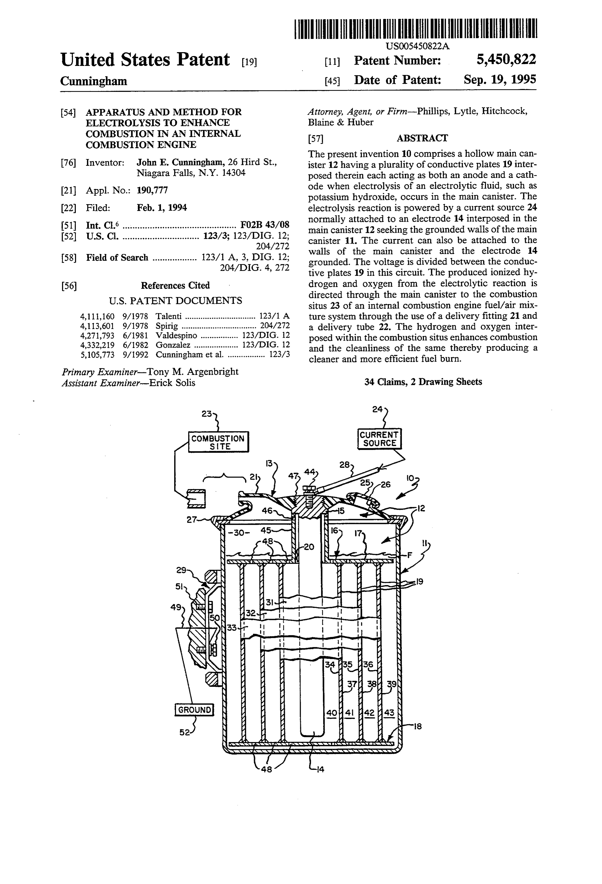
United States Patent (19) 11 Patent Number: 5,450,822 Cunningham (45) Date of Patent: Sep. 19, 1995 54 APPARATUS AND METHOD FOR Attorney, Agent, or Firm-Phillips, Lytle, Hitchcock, ELECTROLYSIS TO ENHANCE Blaine & Huber
COMBUSTION IN AN INTERNAL 57 ABSTRACT
COMBUSTION ENGINE
The present invention 10 comprises a hollow main can 76) Inventor: John E. Cunningham, 26 Hird St., ister 12 having a plurality of conductive plates 19 inter Niagara Falls, N.Y. 14304 posed therein each acting as both an anode and a cath 21 Appl. No.: 190,777 ode when electrolysis of an electrolytic fluid, such as potassium hydroxide, occurs in the main canister. The 22) Filed: Feb. 1, 1994 electrolysis reaction is powered by a current source 24 normally attached to an electrode 14 interposed in the 51 Int. Cl. .............................................. FO2B 43/08 main canister 12 seeking the grounded walls of the main (52) U.S. C. ............................... 123/3; 123/DIG. 12; canister 11. The current can also be attached to the 204/272 walls of the main canister and the electrode 14 58) Field of Search .................. 123/1 A, 3, DIG. 12; grounded. The voltage is divided between the conduc 204/DIG. 4, 272 tive plates 19 in this circuit. The produced ionized hy (56) References Cited drogen and oxygen from the electrolytic reaction is
situs 23 of an internal combustion engine fuel/air mix 4,111,160 9/1978 Talenti................................ 123/1 A ture system through the use of a delivery fitting 21 and 4,113,601 9/1978 Spirig ... ........ 204/272 a delivery tube 22. The hydrogen and oxygen inter 4,271,793 6/1981 Valdespino .. ... 123/DIG. 12 posed within the combustion situs enhances combustion 4,332,219 6/1982 Gonzalez ............. ... 123/DIG. 12 and the cleanliness of the same thereby producing a 5,105,773 9/1992 Cunningham et al. ................. 123/3 cleaner and more efficient fuel burn. Primary Examiner-Tony M. Argenbright
Assistant Examiner-Erick Solis 34 Claims, 2 Drawing Sheets
rsrs r rters
StarSSR
Page 2
Drawing sheet — no readable text.
Page 3
Drawing sheet — no readable text.
Page 4
sites are not attached to the main canister, reducing the
APPARATUS AND METHOD FOR effects of vibration.
ELECTROLYSS TO ENHANCE COMBUSTION IN Accordingly, the invention improves over the prior AN INTERNAL COMBUSTON ENGINE art by solving a variety of problems not addressed by the prior art using simple, straightforward and easily
TECHNICAL FIELD adaptable solutions.
The present invention relates generally to internal DISCLOSURE OF THE INVENTION combustion engines and the use of electrolytically gen The present invention (e.g. 10) provides a device erated hydrogen and oxygen to enhance combustion O producing efficiency and cleanliness and more particularly, to an delivery tofree the hydrogen and oxygen by electrolysis for combustion site of an internal combus electrolyser device designed for use in automobiles or tion engine to increase the combustion efficiency and other vehicles to produce a requisite amount of hydro reduce the pollutant products of combustion. In partic gen and oxygen through the variation of voltage across ular, the preferred embodiment of the device has a hol the system and variation of surface area and orientation 15 low main canister (e.g. 12) with a cup shaped side and of combination anode/cathode conductive plates. botton portion (e.g. 11 ) and a top portion (e.g. 13) BACKGROUND OF THE INVENTION adapted to sealably engage the cup shaped portion; an The typical internal combustion engine generally electrode (e.g. 14) attached to the top portion; an en used in automobiles, trucks and other similar vehicles ergy cartridge (e.g. 16) disposed to fit in the hollow use various fuels for combustion. It is well known burn main canister and positioned about the electrode, hav ing a top plate (e.g. 17) a bottom plate (e.g. 18), and ing of these fuels is not one hundred percent efficient conductive and further, produces large amounts of pollutants as a opening (e.g.plates 20) to (e.g. 19), the top plate having an accommodate the electrode there byproduct of the combustion process. Accordingly, through, and secondary openings (e.g. 46) to allow many attempts have been made to enhance the com 25 easier movement of the released gases to the delivery pleteness of combustion by the introduction of various fitting (e.g. 21) leading to the vehicle engine through a catalysts and additives, including gaseous hydrogen and delivery tube (e.g. 22), the bottom plate also having oxygen, into the burning process. Such attempts were secondary openings (e.g. 46) used to maintain a similar made with the goal of improving combustion efficiency level of fluid throughout the main canister; and an elec and cleanliness, while ensuring the stability of the com 30 trolyte fluid having a volume sufficient to cover the bustion process and viability of engine components. surface area of the conductive plates but leaving air In particular, many attempts have been made in the space (e.g. 30) above the energy cartridge. prior art to use a basic electrolysis reaction of various In operation, the device produces gaseous hydrogen solutions (water or other chemical compositions con and oxygen through an electrolytic reaction. In particu taining oxygen and hydrogen) to produce elemental 35 lar, the charging of the electrode and the grounding of oxygen and hydrogen in gaseous form. These gases, the main canister outer wall creates an electric circuit in known to increase the efficiency of combustion within Series across the conductive plates and the gaps between certain ranges, are then typically introduced either sin the conductive plates filled with the electrolytic fluid. gly or together into the combustion situs to achieve the Each conductive plate acts as both an anode and a cath goal of improved combustion efficiency and concomi 40 Ode. For example, the inner most plate (e.g. 31) has a tant cleanliness. For example, U.S. Pat. Serial No. surface facing the electrode (e.g. 34) and a surface fac 4,111,160 provides a broad overview of the prior art ing the main canister wall (e.g. 37). If a positive charge attempts and the use of the basic electrolysis reaction to is induced on the electrode, it will induce a negative achieve enhanced combustion. charge on the surface of the inner most conductive plate The present invention is an improvement over U.S. 45 facing the electrode (e.g. 37). This will induce a positive Pat. No. 5,105,773 employing unique mesh anodes inter charge on the surface of the inner most conductive plate posed between cathode plates partially submerged in facing the main canister wall (e.g. 37). The surfaces of electrolytic solution to produce hydrogen and oxygen each conductive plate acquire alternating charges by electrolysis. The 773 patent discloses an electrolysis through this process completing a circuit between the system for the improvement of engine efficiency with SO electrode and the grounded wall of the main canister. out the need for storage tanks, pressure valves or the The gaps between the conductive plates (e.g. 40, 41, like in a safe efficient manner. 42, 43) are at least partially filled with electrolyte. The The present invention provides each benefit of the electrolyte in the gaps act as resistors in the system. '773 patent while solving problems not addressed by the Dividing the available voltage between the conductive prior art; e.g. heat energy production from electrolysis, 55 plates by placing the conductive plates in a series circuit connection corrosion from contact with the electrolyte, reduces heat production when compared to systems difficult maintenance of the device and the effects of placing the entire applied voltage on each conductive vibration. Heat production is reduced by using a series plate (e.g. the '773 patent).
circuit with definable resistance cross the entire elec The invention produces a desired amount of hydro trolysis site. The present invention solves the corrosion 60 gen and oxygen by varying the number of conductive problem by placing all electrical connections outside plates, their spacing or varying the voltage applied to the main canister containing the electrolyte. The pres the system. The precise control makes storage tanks, ent invention also provides simplified maintenance over pressure control valves or devices to monitor the reac the prior art by employing easily removable and re tion unnecessary. The free hydrogen and oxygen sur placeable electrolysis sites. Finally, in the prior art, 65 faces at the top portion of the main canister and is then vibrations degraded the canister mounted connections delivered through a delivery fitting through the deliv of the electrolysis sites reducing the life and efficiency ery tube to the combustion site of the fuel/air system of the devices. In the present invention, the electrolysis and is ignited in an ordinary manner, e.g. by a spark
Page 5
plug, as the internal combustion engine functions to face relative to its axis of elongation, or axis of rotation, burn fuel. as appropriate.
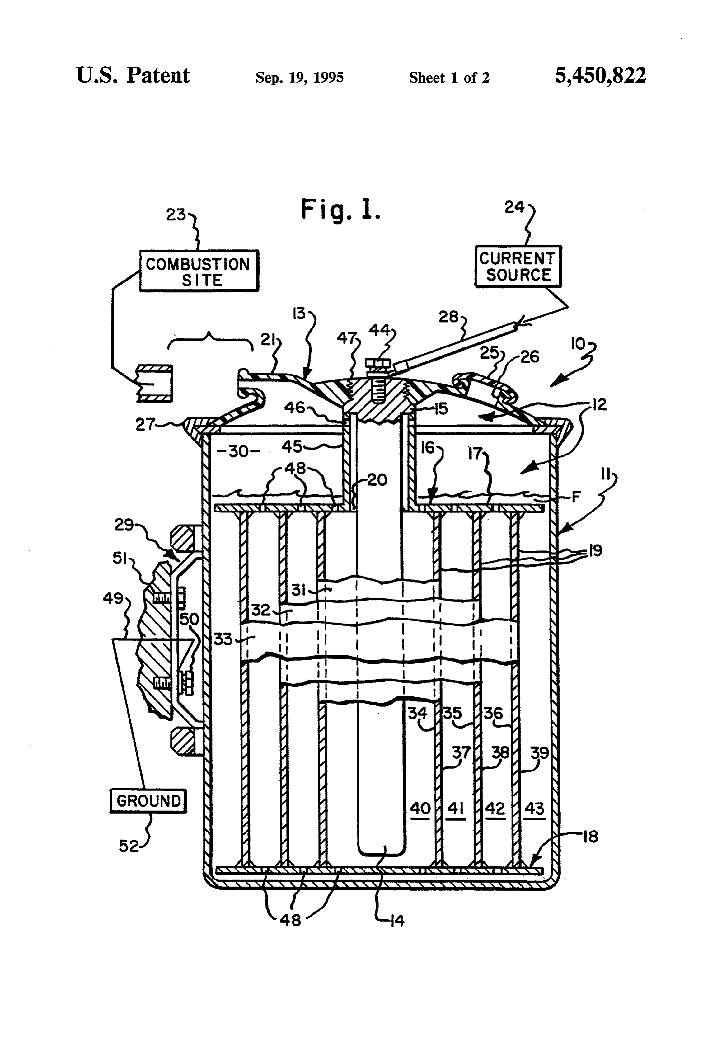
Electrolysis sites in the prior art have been fixed Adverting to FIG. 1., the device 10 is shown togen inside a canister by supports attached to or extending erally comprise a cupshaped side and bottom portion 11 through the canister wall. (See, U.S. Pat. No. 5,231,954, and a top portion 13. The side and bottom portion 11 is the 160 patent and the 773 patent). These mountings normally fabricated from a conductive, corrosion resis are susceptible to breaking, setting the electrolysis sites tant material. The top portion 13 is normally fabricated free inside the canister. Vibrations may also loosen the from light weight PVC material or a similar material to seal where a support extends through the canister wall minimize weight while maintaining durability and seal allowing electrolyte and free hydrogen and oxygen to 10 ing capability. Top portion 13 and side and bottom escape. In the present invention, the electrolysis sites portion 11 are sealably connected using a pressure sensi are not attached to the main canister wall thus reducing tive sealing ring 27 normally made from an elastomer. damage by vibration. As a safety feature, sealing ring 27 is designed to give Thus, a primary object of this invention is to produce way when an excessive pressure is reached inside the hydrogen and oxygen using an electrolyser device 15 main canister. Side and bottom portion 11, when joined where the available voltage is divided between the with the top portion 13, form a main canister 12. Cylin conductive plates reducing heat production. drical electrode 14 has threading on its outside surface A further object of the invention is to produce hydro at one end adapted to engage a hollow screw plug 47 gen and oxygen through electrolysis that may be deliv designed into the inside surface of the top portion 13. ered to an internal combustion engine combustion site 20 The electrode 14 is also adapted to receive a screw 44 in with out need for storage tanks, valves or the like. its top surface, securing to the electrode 14 voltage Still another object of the invention is to produce supply wire 28 leading to a current source 24. The cap hydrogen and oxygen through electrolysis using easily 25 sealably engages a projection 26 of the top portion maintained, repaired and replaceable components. 13. Removal of the cap 25 allows easy access to the Still another object of the invention is to produce 25 interior of the main canister.
hydrogen and oxygen through electrolysis in a system Energy cartridge 16 fits inside the hollow of main with no electrical connections contacting the electro canister 12. A hollow vertical cylinder 45 surrounds an lyte. opening 20 through the top plate large enough to ac Yet another object of the invention is to minimize the commodate the electrode 14 and extends upward where effects of vibration on a system producing hydrogen 30 it contacts a projection 15 of the electrode, thereby, and oxygen through electrolysis to increase the longev stabilizing the energy cartridge 16. The hollow vertical ity and efficiency of the electrolysis system. cylinder 45 also has openings 46 between its inner and These and other objects of the invention will become outer surfaces to allow hydrogen and oxygen produced apparent from the foregoing and ongoing written speci to reach the delivery fitting 21 and thus, the combustion fication, the drawing figures and claims that follow. 35 site 23. The top plate 17 and bottom plate 18 have small BRIEF DESCRIPTION OF THE DRAWINGS openings 48 to allow the hydrogen and oxygen pro duced to easily escape to the delivery fitting 21 and for
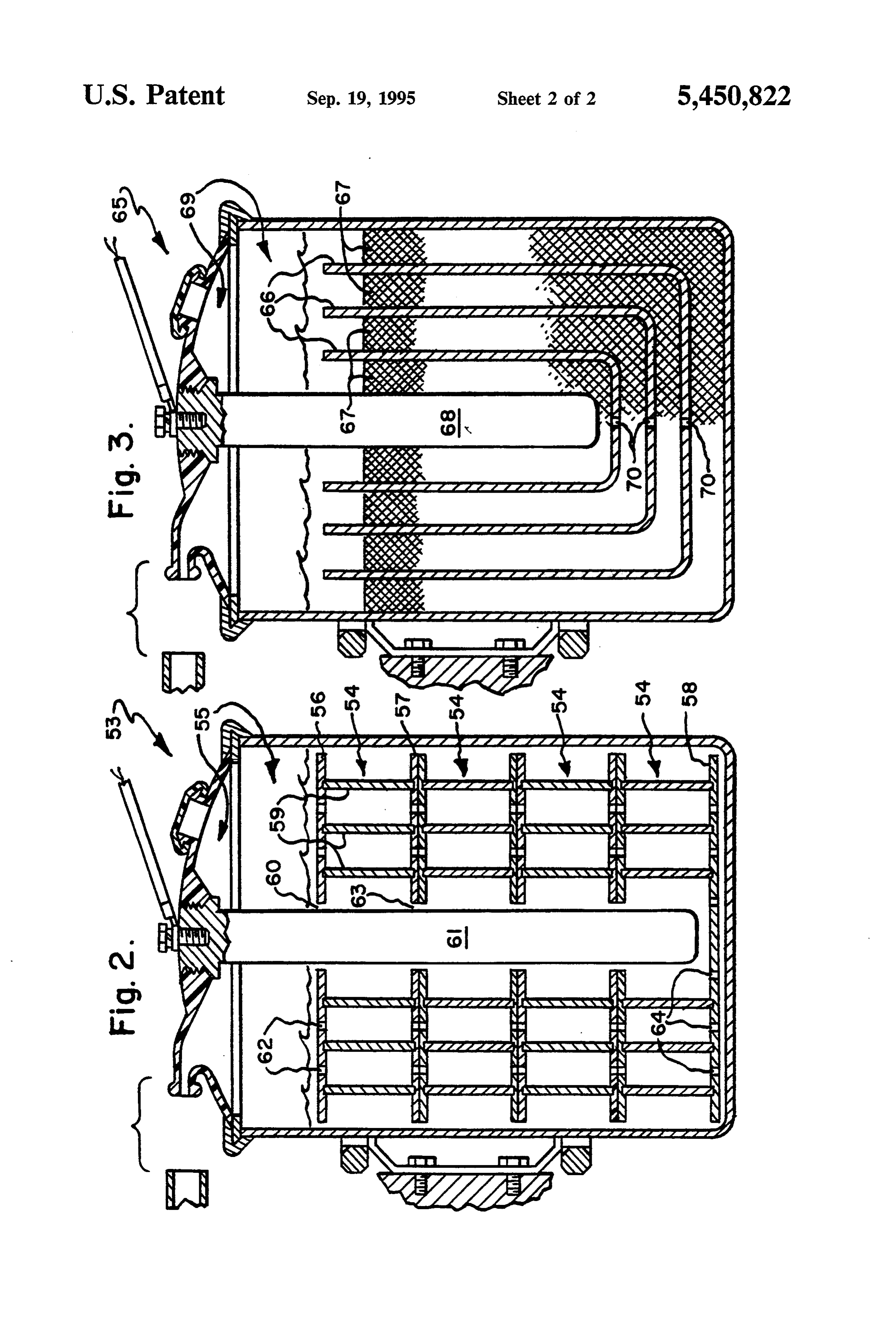
FIG. 1 is a fragmentary longitudinal sectional view of the electrolyte F to seek a common level throughout the preferred embodiment of the device showing the the system. The conductive plates 31, 32 and 33 are thin structure of the energy cartridge. 40 walled cylinders made of conductive material (e.g. FIG. 2 is a fragmentary longitudinal sectional view of stainless steel) and are disposed about the electrode 14. a second embodiment of the device showing a plurality Each conductive plate 31, 32 and 33 is attached to the of energy cartridges and their structure. top plate 17 and the bottom plate 18. The electrode 14 FIG.3 is a fragmentary longitudinal sectional view of is positioned inside the hollow vertical cylinder 45 and a third embodiment of the device showing the interposi 45 through an opening 20 in the top plate 17 allowing the tion of a plurality of cup-shaped conductive plates and conductive plates to circle the electrode. mesh spacers. Bracket 29 is attached to the outside surface of the MODE(S) OF CARRYING OUT THE INVENTION tached side and bottom portion 11. An electrical wire 49 at to a screw 50 on the bracket leads to a grounded
At the outset, it should be clearly understood that like 50 part of the internal combustion engine 52. Screws 50 reference numerals are intended to identify the same and 51 mount the main canister to a grounded part of structural elements, portions or surfaces consistently the vehicle.
throughout the several drawings figures, as such ele Electrolytic fluid F is interposed within the hollow of ments, portions or surfaces may be further described or the main canister in a sufficient volume to cover all or a explained by the entire written specification, of which 55 major portion of the conductive plates. Typically, the this detailed description is an integral part. Unless oth electrolytic fluid is potassium hydroxide or a similar erwise indicated, the drawings are intended to be read compound able to generate free oxygen and hydrogen (e.g., cross-hatching, arrangement of parts, proportion, ions as a result of an electrolytic reaction. The volume degree, etc.) together with the specification, and are to of fluid F will generally not entirely fill the hollow main be considered a portion of the entire written description 60 canister and a space 30 will typically be left at the top of this invention. As used in the following description, portion thereof.
the terms “horizontal”, “vertical”, “left”, “right”, “up' In operation, the device is interposed within the en and "down', as well as adjectival and adverbial deriva gine compartment of an internal combustion engine tives thereof (e.g., "horizontally”, “rightwardly', "up fuel/air mixture system and is arranged to communicate wardly', etc.), simply refer to the orientation of the 65 with the combustion system of the vehicle. The device illustrated structure as the particular drawing figure is also connected to a current source 24, e.g. the genera faces the reader. Similarly, the terms "inwardly' and tor or battery, so a small amount of current may be "outwardly' generally refer to the orientation of a sur provided through the device.
Page 6
In a normal electrolysis reaction, a positive current is tics could be used. Moreover, the number and dimen supplied to the electrode. The current jumps gaps 40, sions of the conductive plates, mesh spacers and energy 41, 42 and 43 defined by the conductive plates, the cartridges may readily be varied to produce an appro electrode 14 and the side and bottom portion 11. As a priate reaction.
result, each conductive plate acts as both an anode and Also, the material used for the conductive plates, a cathode. When a positive charge is induced on the stainless steel, is merely an example as many conductive electrode 14, surfaces 34, 35 and 36 act as cathodes and materials are appropriate.
surfaces 37, 38 and 39 act as anodes. The electrolyte in These and other modifications and changes to the gaps 40, 41, 42 and 43 act as resistors in the circuit. invention would be readily apparent to one of ordinary Adverting to FIG. 2. a second embodiment of the 10 skill in the art and anticipated by the specification and invention 53 is the same in all respects to the preferred description of the invention, as well as the following embodiment shown in FIG. 1. except for the use of claims.
multiple energy cartridges 54 instead of a single energy I claim:
cartridge. A series of cylindrical energy cartridges 54 1. An electrolyser device for use in an internal com are stacked one on top of another inside the main canis 15 bustion engine fuel/air mixture system for enhancing ter 55. Each energy cartridge has a top plate 56, a bot combustion, comprising:
tom plate 57 and conductive plates 59. Each top plate a main canister, interposed within said internal com has an opening 60 between its upper and lower surface bustion engine fuel/air mixture system, said main adapted to receive the electrode 61 therethrough and canister having a top portion and a bottom portion secondary openings 62 to allow movement of produced 20 and side portions forming a hollow cavity, adapted hydrogen and oxygen and electrolyte throughout the to sealably contain a fluid therein and having elec main canister 55. Each bottom plate 57 except bottom trical connector means operably engaged on the plate 58, has an opening 63 between its upper and lower outside of said main canister; surfaces adapted to receive the electrode 61 there through. Bottom plate 58 does not have an opening 25 a delivery main fitting interposed on the top surface of said canister and forming a communicating pas between its upper and lower surfaces so the charge sageway between said inside hollow of said main induced on the electrode 61 will not leak to the main canister 55 bottom without crossing conductive plates canister and outside of said main canister; 59. Each bottom plate 57, including bottom plate 58, has a delivery tube flexibly attached to said outside por secondary openings 64 to allow movement of produced 30 tion of said delivery fitting adapted to carry fluids hydrogen and oxygen and electrolyte throughout the therethrough;
main canister 55. an electrode arranged within said main canister hav Adverting to FIG. 3., a third embodiment of the ing electrical connector means; invention 65 is the same in all respects to the preferred an energy cartridge arranged within said main canis embodiment shown in FIG. 1. except for the substitu 35 ter, said energy cartridge comprising a top plate, a tion of a plurality of cup-shaped conductive plates 66 bottom plate and a plurality of conductive plates, separated by cup-shaped mesh spacers 67 for the energy said top plate having an upper surface, a lower cartridge. Accordingly, the inner portion of main canis surface and an opening between said upper surface ter 69 has an electrode 68 axially positioned at the cen and said lower surface adapted to receive said elec ter of a series of cylinders, one within another, alternat trode therethrough, said bottom plate having an ing between mesh spacer 67 and conductive plate 66. upper surface and a lower surface, and said con The mesh spacers 67 are non-deforming and made ductive plates interposed between said top plate from a resilient nonconductive material. The conduc and said botton plate and disposed about said elec tive plates are made from a conductive material and trode, said conductive plates further comprising a have openings 70 between their inner and outer surfaces 45 surface facing the inside surface of said main canis to allow movement of produced hydrogen and oxygen ter and a surface facing said electrode; and electrolyte through out the main canister 69. an electrolytic fluid containing hydrogen and oxy The inner and outer diameters of the conductive gen, interposed within said main canister such that plates 66 and the mesh spacers 67 are such that each the surface area of said conductive plates are cov conductive plate and mesh spacer fits tightly one within 50 ered thereby;
another, thus reducing movement and vibration. A whereby, upon application of voltage differential series circuit forms across the areas between the con between the outside of said main canister and said ductive plates 66 filled by the spacers 67 and electrolyte electrode across said conductive plates, an electrol when a charge is induced on the electrode 68 inducing ysis reaction occurs freeing gaseous hydrogen and the conductive plates to act as both anodes and cath 55 oxygen through said delivery valve and said deliv odes. ery tube dependent upon said orientation of said The space between the conductive plates is easily members.
altered by changing the diameter of the conductive 2. The device according to claim 1 wherein said top plates 66 and corresponding changes in the diameters of plate and said bottom plate of said energy cartridge are the mesh spacers 67. 60 non-conductive.
MODIFICATIONS TO THE INVENTION 3. The device according to claim 1 wherein said top plate of said energy cartridge further comprises second
It is clear from the specification, drawings and de ary openings between said upper surface and said lower scriptions of the invention that many modifications and surface.
changes may be made without departing from the in 65 4. The device according to claim 1 wherein said bot vention. tom plate of said energy cartridge further comprises For instance, although potassium hydroxide is used as secondary openings between said upper surface and said the electrolytic fluid, other fluids of similar characteris lower surface.
Page 7
5. The device according to claim 1 wherein said con 13. An electrolyser device for use in an internal com ductive plates are stainless steel. bustion engine fuel/air mixture system for enhancing 6. The device according to claim 1 wherein said en combustion, comprising:
ergy cartridge is of unitary construction. a main canister, interposed within said internal com 7. An electrolyser device for use in an internal com bustion engine fuel/air mixture system, said main bustion engine fuel/air mixture system for enhancing canister having a top portion and a bottom portion combustion, comprising: and side portions forming a hollow cavity, adapted a main canister, interposed within said internal com to sealably contain a fluid therein and having elec bustion engine fuel/air mixture system, said main trical connector means operably engaged on the canister having a top portion and a bottom portion 10 outside of said main canister; and side portions forming a hollow cavity, adapted a delivery fitting interposed on the top surface of said to sealably contain a fluid therein and having elec main canister and forming a communicating pas trical connector means operably engaged on the sageway between said inside hollow of said main outside of said main canister;
a delivery fitting interposed on the top surface of said 15 a delivery and canister outside of said main canister;
tube flexibly attached to said outside por main canister and forming a communicating pas tion of said delivery fitting adapted to carry fluids sageway between said inside hollow of said main therethrough;
canister and outside of said main canister; an electrode arranged within said main canister hav a delivery tube flexibly attached to said outside por ing electrical connector means operably engaged; tion of said delivery fitting adapted to carry fluids 20 a plurality of conductive plates interposed within said therethrough;
an electrode arranged within said main canister hav inside of said main canister, said conductive plates ing electrical connector means operably engaged; further comprising a hollow shape such that said a plurality of energy cartridges arranged within said conductive plates are adapted to be spaceably ar main canister, each said energy cartridge compris 25 ranged one within another;
ing a top plate, a bottom plate and a plurality of a plurality of non-conductive mesh spacers inter conductive plates, said top plate having an upper posed within said hollow of said main canister, said surface, a lower surface and an opening between mesh spacers comprising a hollow shape each of said upper surface and said lower surface adapted preselected dimensions such that each said mesh to receive said electrode therethrough, said bottom spacer is adapted to be arranged one within another plate having an upper surface and a lower surface and within the spaces between said conductive and an opening between said upper surface and said plates;
lower surface adapted to receive said electrode an electrolytic fluid containing hydrogen and oxy therethrough, and said conductive plates inter gen, interposed within said main canister such that posed between said top plate and said bottom plate 35 the surface area of said conductive plates are cov and disposed about said electrode, said conductive ered thereby;
plates further comprising a surface facing the inside whereby, upon application of voltage differential of said main canister and a surface facing said elec between the outside of said main canister and said trode; electrode across said conductive plates, an electrol an electrolytic fluid containing hydrogen and oxy ysis reaction occurs freeing gaseous hydrogen and gen, interposed within said main canister such that oxygen through said delivery valve and delivery the surface area of said conductive plates are cov tube dependent upon said orientation of said con ered thereby; ductive plates.
whereby, upon application of voltage differential 14. The device according to claim 13 wherein said between the outside of said main canister and said 45 conductive plates and said mesh spacers are cup shaped. electrode across said conductive plates, an electrol 15. The device according to claim 13 wherein said ysis reaction occurs freeing gaseous hydrogen and conductive plates and said mesh spacers are cylinders. oxygen through said delivery valve and said deliv 16. The device according to claim 13 wherein said ery tube dependent upon said orientation of said conductive plates further comprise a plurality of open members. 50 ings between the inside surface of said hollow shape and 8. The device according to claim 7 wherein said bot outside surface of said hollow shape.
tom plate of said energy cartridge disposed about the 17. The device according to claim 13 wherein said bottom of said electrode has an upper surface and a conductive plates are made of stainless steel. lower surface. 18. In an internal combustion engine fuel system hav 9. The device according to claim 7 wherein said top 55 ing a combustion site, the method of providing gaseous plate of each said energy cartridge further comprises hydrogen and oxygen through electrolysis to enhance secondary openings between said upper surface and said combustion, comprising the steps of: lower surface. providing a hollow main canister within said fuel 10. The device according to claim 7 wherein said system adapted to sealably contain a fluid and hav bottom plate of each said energy cartridge further com ing electrical connector means operably engaged prises secondary openings between said upper surface on the outside of said main canister; and said lower surface. providing a delivery fitting interposed on the top 11. The device according to claim 8 wherein said surface of said hollow main canister such that there bottom plate of each said energy cartridge further com is a communicating passageway between said main prises secondary openings between said upper surface 65 canister hollow inside and outside; and said lower surface. providing a delivery tube flexibly attached to said 12. The device according to claim 7 wherein said delivery fitting and adapted to carry a fluid there conductive plates are stainless steel. through;
Page 8
providing an electrode arranged within said main providing a plurality of energy cartridges arranged canister having electrical connector means outside within said main canister, said energy cartridge said main canister; comprising a top plate, a bottom plate and a plural providing an energy cartridge interposed within said ity of conductive plates, said top plate having an hollow main canister comprising a top plate, a upper surface, a lower surface and an opening be bottom plate and a plurality of conductive plates, tween said upper surface and said lower surface said top plate having an upper surface, a lower adapted to receive said electrode therethrough, surface and an opening between said upper surface said bottom plate having an upper surface and a and said lower surface adapted to receive said elec lower surface and an opening between said upper trode therethrough, said bottom plate having an IO surface and said lower surface adapted to receive upper Surface and a lower Surface, and said con said electrode therethrough, and said conductive ductive plates interposed between said top plate plates interposed between said top plate and said and said bottom plate and disposed about said elec bottom plate and disposed about said electrode, trode, each conductive plate further comprising a said conductive plates further comprising a surface surface facing the inside surface of said main canis 15 facing the inside of said main canister and a surface ter and a surface facing said electrode; facing said electrode;
providing an electrolytic fluid containing hydrogen providing an electrolytic fluid containing hydrogen and oxygen, interposed within said main canister and oxygen, interposed within said main canister such that the surface area of said conductive plates such that the surface area of said conductive plates is covered thereby; is covered thereby;
varying the number of said conductive plates, the varying the number of said conductive plates, the surface area of said conductive plates, the distance surface area of said conductive plates, the distance between said conductive plates and the voltage between said conductive plates and the voltage applied to the system such that on application of 25. applied to the system such that on application of the voltage, electrolysis of said electrolytic fluid the voltage, electrolysis of said electrolytic fluid occurs such that a desired amount of hydrogen and occurs such that a desired amount of hydrogen and oxygen are produced; oxygen are produced;
venting said produced hydrogen and oxygen gas venting said produced hydrogen and oxygen gas through said delivery fitting and said delivery tube 30 through said delivery fitting and said delivery tube to said combustion site of said internal combustion to said combustion site of said internal combustion engine fuel/air mixture system; engine fuel/air mixture system; whereby the introduction of gaseous hydrogen and whereby the introduction of gaseous hydrogen and oxygen into the combustion process enhances the oxygen into the combustion process enhances the completeness and cleanliness of the same. 35 completeness and cleanliness of the same. 19. The method according to claim 18 where said top 25. The method according to claim 24 where said plate and said bottom plate provided are non-conduc bottom plate of said energy cartridge disposed about the tive. bottom of said electrode provided has an upper surface 20. The method according to claim 18 where said top and a lower surface.
plate of said energy cartridge provided further com 40 26. The method according to claim 24 where said top prises secondary openings between said upper surface plate of each said energy cartridge provided further and said lower surface. comprises secondary openings between said upper sur 21. The method according to claim 18 where said face and said lower surface.
bottom plate of said energy cartridge provided further 27. The method according to claim 24 where said comprises secondary openings between said upper sur 45 bottom plate of each said energy cartridge provided has face and said lower surface. Secondary openings between said upper surface and said 22. The method according to claim 18 where said lower surface.
conductive plates provided are stainless steel. 28. The method according to claim 25 where said 23. The method according to claim 18 where said bottom plate of each said energy cartridge provided has energy cartridge provided is of unitary construction. SO secondary openings between said upper surface and said 24. In an internal combustion engine fuel system hav lower surface.
ing a combustion site, the method of providing gaseous 29. The method according to claim 24 where said hydrogen and oxygen through electrolysis to enhance conductive plates provided are stainless steel. combustion, comprising the steps of: 30. In an internal combustion engine fuel system hav providing a hollow main canister within said fuel 55 ing a combustion site, the method of providing gaseous system adapted to sealably contain a fluid and hav hydrogen and oxygen through electrolysis to enhance ing electrical connector means operably engaged combustion, comprising the steps of:
on the outside of said main canister; providing a hollow main canister within said fuel providing a delivery fitting interposed on the top System adapted to sealably contain a fluid and hav surface of said hollow main canister such that there 60 ing electrical connector means operably engaged is a communicating passageway between said main on the outside of said main canister; canister hollow inside and outside; providing a delivery fitting interposed on the top providing a delivery tube flexibly attached to said surface of said hollow main canister such that there delivery fitting and adapted to carry a fluid there is a communicating passageway between said main through; 65 canister hollow inside and outside; providing an electrode arranged within said main providing a delivery tube flexibly attached to said canister having electrical connector means outside delivery fitting and adapted to carry a fluid there said main canister; through;
Page 9
providing an electrode arranged within said main the voltage, electrolysis of said electrolytic fluid canister having electrical connector means outside occurs such that a desired amount of hydrogen and said main canister; oxygen are produced;
providing a plurality of conductive plates interposed venting said produced hydrogen and oxygen gas within said inside of said main canister, said con 5 through said delivery fitting and said delivery tube ductive plates comprise a hollow shape such that to said combustion site of said internal combustion each said conductive plate is adapted to be spacea engine fuel/air mixture system; bly arranged one within another; . whereby the introduction of gaseous hydrogen and providing a plurality of non-conductive mesh spacers oxygen into the combustion process enhances the interposed within said hollow of said main canister, 10 completeness and cleanliness of the same. each of said mesh spacers comprising a hollow 31. The method according to claim 30 where said shape each of preselected dimensions such that conductive plates and said mesh spacers provided are each of said mesh spacers is adapted to be arranged cup shaped.
one within another and within the spaces between 32. The method according to claim 30 where said said conductive plates; 5 conductive plates and said mesh spacers provided are providing an electrolytic fluid containing hydrogen cylinders.
and oxygen, interposed within said main canister 33. The method according to claim 30 where said such that the surface area of said conductive plates conductive plates provided further comprise a plurality is covered thereby; of openings between the inside surface of said hollow varying the number of said conductive plates, the 20 shape and outside surface of said hollow shape. surface area of said conductive plates, the distance 34. The method according to claim 30 where said between said conductive plates and the voltage conductive plates provided are stainless steel. applied to the system such that on application of :k ck :k ck ck
Provenance
- Collection
- Cited prior art
- Original PDF
- patentimages.storage.googleapis.com →
- Filed
- 1994-02-01
- Pages
- 9
- Method
- pdftotext (the PDF's own text layer) + pdftoppm 300dpi page scans
- Source
- Google Patents bibliographic record
- Granted
- 1995-09-19
- Inventors
- John E. Cunningham
- Transcribed from
- patentimages.storage.googleapis.com →