patent · US5799624
Electrolytic fueling system for engine
1 September 1998
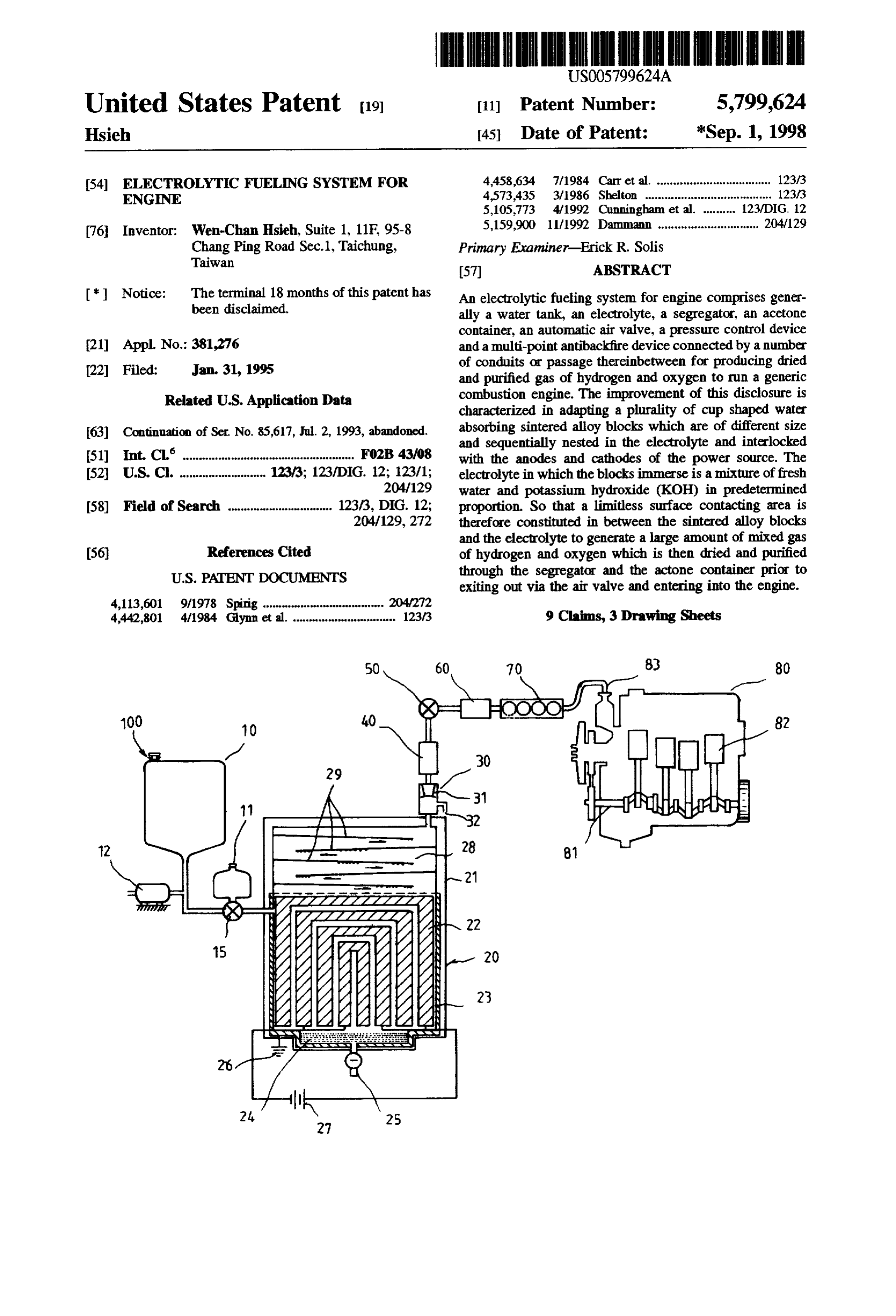
Page 1 — bibliographic record
United States Patent 19 11 Patent Number: 5,799,624 Hsieh 45) Date of Patent: *Sep. 1, 1998 54 ELECTROLYTC FUELNG SYSTEM FOR 4,458,634 7/1984 Carret al. ................................... 123/3 ENGINE 4,573,435 3/1986 Shelton ................... ............ 123/3
76 Inventor: Wen-Chan Hsieh, Suite 1, 11F, 95-8 5,159,900 11/1992 Dammann ............................... 204/129 Chang Ping Road Sec.1, Taichung, Primary Examiner-Erick R. Solis
Taiwan
Notice: The terminal 18 months of this patent has An electrolytic fueling system for engine comprises gener been disclaimed. ally a water tank, an electrolyte, a segregator, an acetone container, an automatic air valve, a pressure control device 21 Appl. No.: 381,276 and a multi-point antibackfire device connected by a number 22 Filed: Jan. 31, 1995 of conduits or passage thereinbetween for producing dried and purified gas of hydrogen and oxygen to run a generic
Related U.S. Application Data combustion engine. The improvement of this disclosure is characterized in adapting a plurality of cup shaped water (63) Continuation of Ser. No. 85,617, Jul. 2, 1993, abandoned. absorbing sintered alloy blocks which are of different size and sequentially nested in the electrolyte and interlocked (51) Int. Cl'...................... FO2B 4308 with the anodes and cathodes of the power source. The (52) U.S. C. ... . 123/3; 123/DIG. 12; 123/1; electrolytein which the blocks immerse is a mixture of fresh 204/129 water and potassium hydroxide (KOH) in predetermined 58) Field of Search ....................... 123/3, DIG. 12; proportion. So that a limitless surface contacting area is 204/129, 272 therefore constituted in between the sintered alloy blocks and the electrolyte to generate a large amount of mixed gas 56 References Cited of hydrogen and oxygen which is then dried and purified
exiting out via the air valve and entering into the engine.
4,442,801 4/1984 Glynn et al. ... 123/3 9 Claims, 3 Drawing Sheets
wAA
Page 2
Drawing sheet — no readable text.
Page 3
Drawing sheet — no readable text.
Page 4
Drawing sheet — no readable text.
Page 5
ELECTROLYTC FUELING SYSTEM FOR themselves one by one as the largest one of them is at the ENGINE outmost position. A pair of 12-volt batteries are adapted to electrically connect with the four layer of the blocks in the
This is a continuation application of an U.S. application manner that the first and third layers are connected with the Ser. No. 08/085,617 filed Jul. 2, 1993, now abandoned. postive poles and the second and fourth layers are connected with the negative poles of the electrode.
BACKGROUND OF THE INVENTION Because of that the electrolyte is in weak alkalinity and The present invention relates to a fueling system for the molecules of the water and KOH are sizably smaller than engine, more particularly to an electrolytic fueling system to the crevices inside the whole block so that the blocks are produce gas of hydrogen and oxygen instead of the conven entirely permeable in the electrolyte in a preferable elec tional vaporized gasoline to start an engine, which utilizes trolysis condition.
water absorbing sintered alloy blocks incorporated with a When the power is set on in maximum current, both ionic hydrolysis method to generate adequate gas of hydrogen and hydrogen and ionic oxygen are generated from the electro oxygen therein. lyte as the ionic oxygen trends to the cathode and the ionic Conventional vaporized gasoline fueling systems for 15 hydrogen trends to the anode of the electrode and then they engines or generators are known to create a great deal of conduct a neutralized reaction in the blocks prior to become waste gas of carbon monoxide (CO) and hydrocarbon mixture of vaporized gas of hydrogen and oxygen belching (CxHy) which not only cause environmental pollution but out of the outmost block. The mixture then ascends through also jeopardize the ozonosphere around the earth. Scientists a plurality of drip plates entered into the segregator for a and engineers around the world are trying hard during recent process of dehydration and goes up continuously through the years to search for substitute resources for vaporized gaso acetone container for decarbonizing and cooling of prior to line in order to eliminate environmental pollution so as to becoming a dried and purified gas of hydrogen and oxygen develop battery or solar engine systems. Some of the coun gathering at the air valve which is under control of a micro tries encourage their drivers to use natural gas instead of computer will transfer the gas entered into the cylinders of gasoline to run their cars. But it is still facing a lot of an engine after it sequentially passes through the pressure problems of limitation, especially the solar engine system control device, the multi-point antibackfire device and an air which is not adaptable in raining seasons. ingress.
SUMMARY OF THE PRESENT INVENTION
The gas under high pressure will be combustioned by the sparks and exploded inside the cylinders to run the engine in
The main object of the present invention is to provide an proper speed without exhausting the waste gas except the electrolytic fueling system for an engine or generator by vapor out of the engine.
utilizing the water absorbing sintered alloy blocks incorpo The objects and advantages of the present invention will rated with a hydrolysis method which enables an unlimited become more apparent by reference to the following contact surface in between the electrolyte and the electrode 35 description thereof when read in conjunction with the to speed up their active chemical reaction in generating attached drawings.
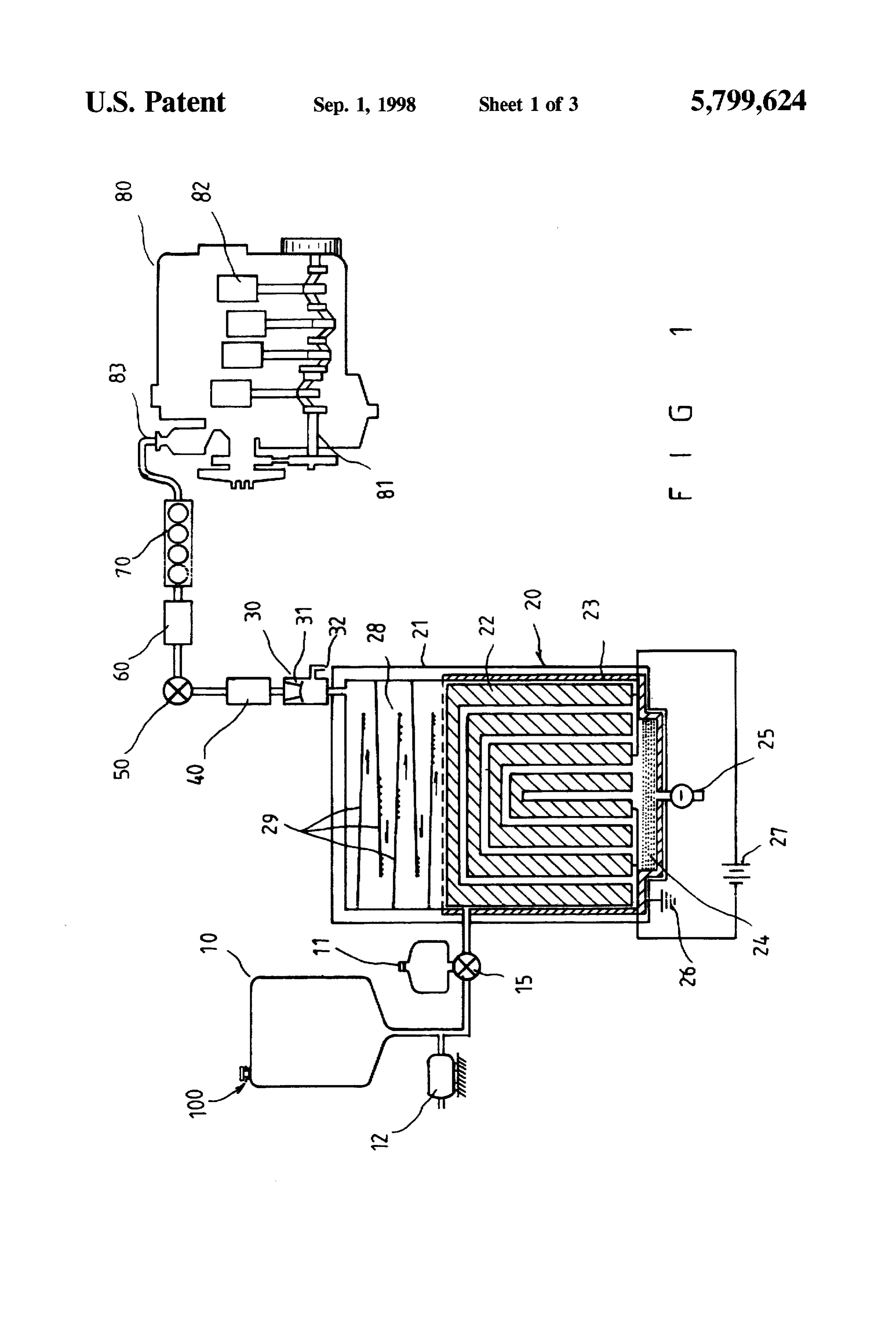
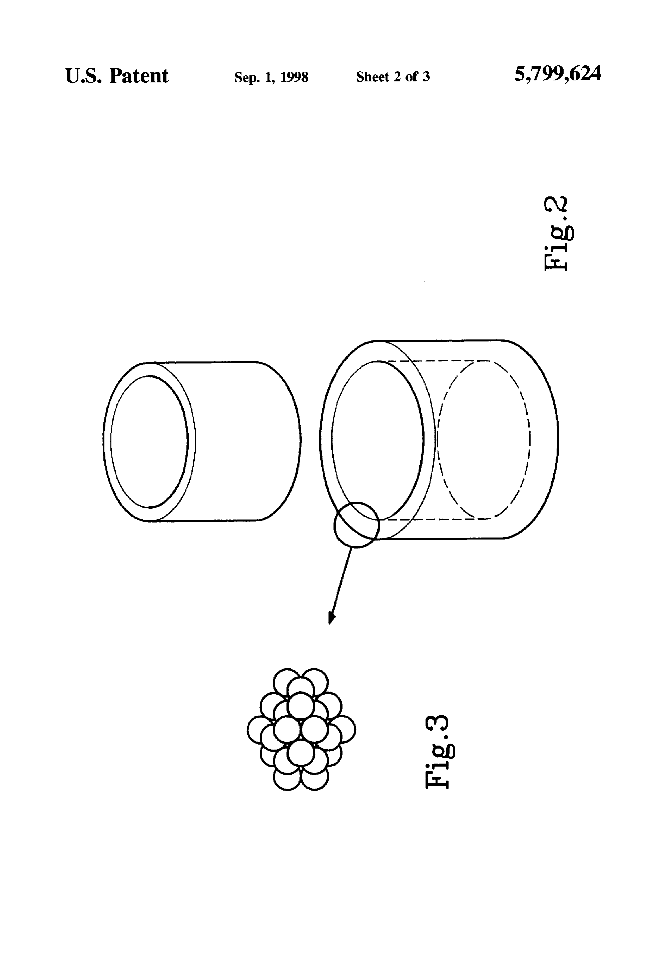
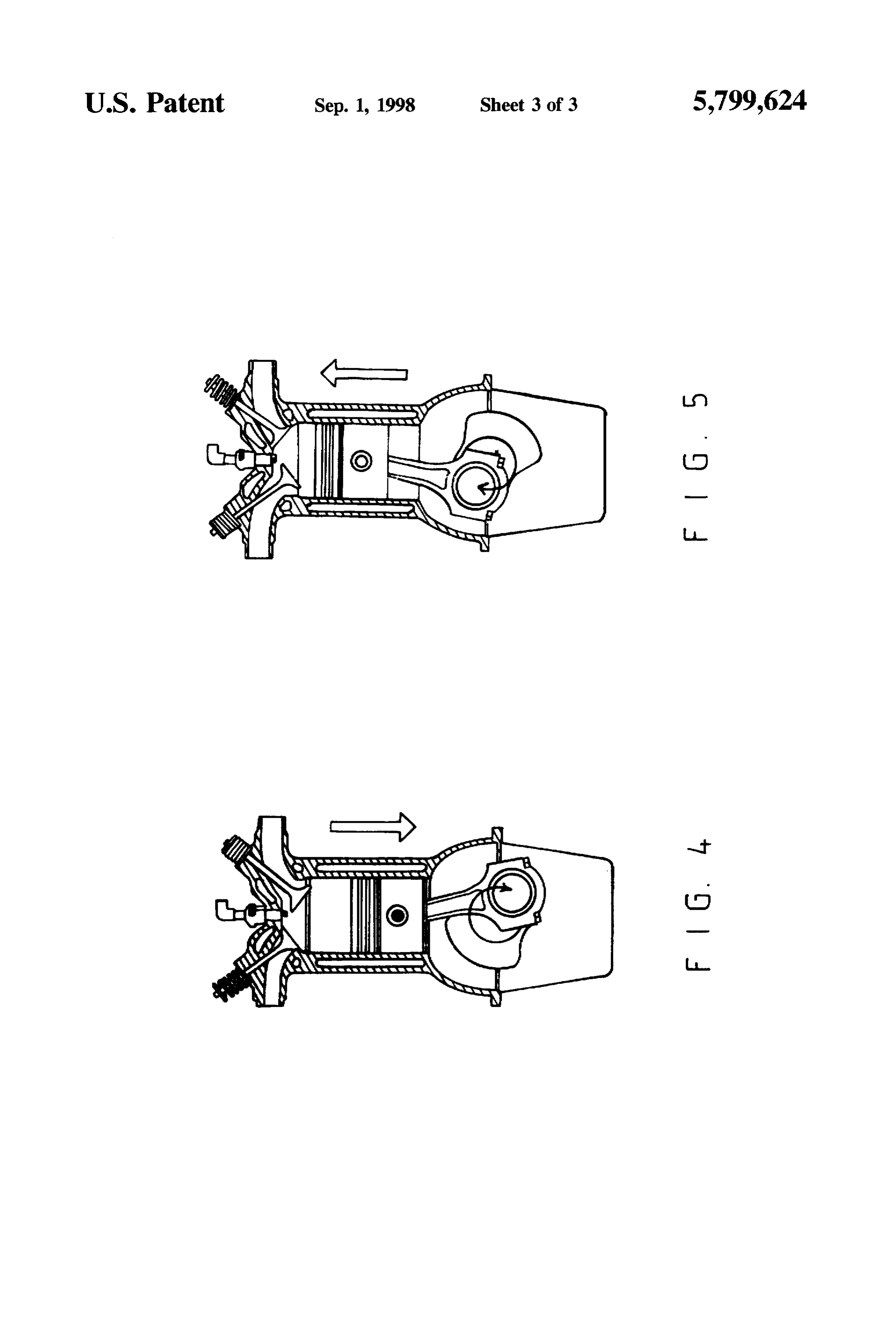
adequate gas of hydrogen and oxygen for running an engine without creating the waste gas. BRIEF DESCRIPTION OF THE DRAWENGS Another object of this invention is to provide an electro FIG. 1 is a schematic diagram to show the preferred lytic fueling system by adapting the electrolyte of mixed 40 embodiment of the present invention, potassium hydroxide (KOH) and fresh water instead of FIG. 2 is a perspective view to show the structure of a petroleum chemical product in order to reduce the cost of water absorbing sintered alloy block according to the present application. invention,
Accordingly, the present invention of an electrolytic fuel FIG.3 is a perspective view to show a structurally curdled ing system comprises generally a fresh water tank, a KOH 45 particles inside a sintered alloy block according to the tank, an electrolyzer, a segragator, an acetone container, an present invention, air valve, a pressure control device and a multi-point anti backfire device thereof. The most significant improvement gasFG. 4 is a sectional view to show the condition where the being fueled in the cylinder of a engine, and of this invention is characterized in adapting a plurality of FIG.S is a sectional view to show the condition where the cup shaped water absorbing sintered alloy blocks spacedly arranged inside the electrolyzer, which are made of particles vapor being exhuasted from the engine. of nickel alloy and moulded under high pressure with instant DETALED DESCRIPTION OF THE heat treatment in a high frequency furnace or by a maximum PREFERRED EMBODMENT OF THE PRESENT current instant short circuit discharging method at a tem INVENTON perature of about 1500-2000° C. The particles are so 55 tightly arranged inside the mould as each one of them must Referring to FIG. 1 of the drawings, the present invention contacts with twelve others on their outer peripheries and of an electrolytic fueling system for engine comprises gen puncture each other under high pressure and high tempera erally a recruiting unit 100 composed of a fresh water tank ture prior to curdle into dimensionally different cup shaped 10 incorporated with a KOH tank 11, an automatic pump 12, blocks. 60 a three-port valve 15 and a plurality of conduits 16 inter The electrolyte inside the electrolyzer is a mixture of communicated thereinbetween, an electrolyzer 20, a segre potassium hydoxide (KOH) and fresh water in predeter gator 30, an acetone container 40, an automatic air valve 50, mined proportion which is supplied from the water and a pressure control device 60 and a multi-point antibackfire KOH tanks under control of an ingress valve. Four dimen device 70, sionally different cup shaped blocks are arranged upside 65 The most significant improvement of this invention is down on the bottom of the electrolyzer to form four layers characterized in adapting a plurality of cup shaped water in the manner that they are sequentially surrounded by absorbing sintered alloy blocks 22 (see FIG. 2) spacedly
Page 6
arranged inside the electrolyzer 20, which are made of nickel the leakage and the pressure of the gas and breaking up the alloy particles and moulded under high pressure and instant current when comes up the hazard.
heat treatment in a high frequency furnace or by a maximum The potassium hydroxide (KOH) mixed in the electrolyte current instant short circuit discharging method at a tem is of a non-toxic, non-erosion and medium alkaline solution perature of about 1500-2000° C. The particles of the nickel and it's alkality will become weak when mixed with fresh alloy inside the mould are so tightly arranged as each of water which is of a favorable condition for maximum them must contacts with at least twelve others on their outer electrolyzing, peripheries (see FIG. 3) and punctures each other under water and KOH solution and because of that the molecule of the fresh above mentioned high pressure and high temperature prior inside whole block 22 sois sizably smaller than the crevices to curdle into dimensionally different cup shaped blocks 22. 10 permeable in the electrolyte to achieveblocks that the 22 are entirely a limitless electolytic
The electrolyzer 20 comprises a cylindrical housing 21 contacting surface area. In addition to the catalytically active enclosed therein an elctrolytic sink 23 on the lower portion, property of the nickel, adequate ionic hydrogen and ionic an air cell 28 on the upper portion and a less diameter oxygen will be generated from the electrolyte when the circular impurity trough 24 on the bottom communicated to power is set on in maximum current. Normally, the ionic the electrolytic sink 23 and an egress 25 for discharging the 15 oxygen trends to the anodes so as the ionic hydrogen trends impurities from the sink 23. The electrolytic sink 23 has to the cathodes of the electrode and then they conduct a reinforced on the inner periphery a layer of heat insulation neutralized reaction in the alloy blocks 22 prior to becoming material and contains electrolyte and a plurality of the a mixture of vaporized gas of hydrogen and oxygen belching dimensionally different cup shaped water absorbing sintered from the outmost block 22 which is of a first filter to alloy blocks 22 therein. The alloy blocks 22 are disposed dehydrate the vaporized gas. The air cell 28 on the top of the upside down on the bottom of the sink 23 and arranged so electrolyzer 23 proceeds the second step of dehydration by as they are spacedly and sequentially encircled each other in the drip plates 29 therein, then the vaporized gas is passed the manner that the largest one of them is at the outmost through and entered into the segregator 30 for the final step position adjacent the inner periphery of the sink 23. A pair of dehydration. The dried gas of hydrogen and oxygen flows of 12-volt batteries are adapted as the power source 27 to continuously from the segregator 30 into the acetone con electrically connect with the alloy blocks 22 inside the sink tainer 40 for a decarbonizing and cooling off process prior 23 in the manner that the first and the third layers of the to being sent out through the air valve 50, the pressure blocks connect with a series of the anodes where the second control device and the multi-point antibackfire 70 entered and the fourth layers thereof connect with a series of the into the engine 80 which is of a generic type has cranks 81 cathodes of the electrode. A grounding means 26 is also and cylinders disposed therein. When the gas of mixed
arranged in the circuit. hydrogen and oxygen incorporated with fresh air is pressed The air cell 28 on the upper portion of the housing 21 in, it will be combusted and exploded in the cylinders 82 to comprises a plurality of semi-circular drip plates 29 run the engine 80 perfectly with out creating the waste gas spacedly and alternately secured on their outward ends to the except the vapor exhuasted out of the engine 80. inner periphery of the cell 28 and their inwardends extended 35 The recruiting unit 100 is the one of the important slantly towerd the opposite side and terminated at a prede components in the electrolytic fueling system because of termined position, and a passage on the top near the edge of that the water is quite consumed in the electrolyte 23. Thus, the housing 21 provided to perpendicularly connect with the the three port valve 15 incorporated with the automatic central bottom of the segregator 30 for passing through the damp gas of the hydrogen and oxygen from the cell 28 into pump 12 are sensitive to the water level and the KOH ratio of the electrolyzer and timely pump the freshwater from the the segragator 30. water tank 10 and the KOH solution from the KOH con The segregator 30 comprises a cylindrical housing tainer 11 into the electrolyzer 23.
enclosed therein a roughly conical filter plate 31 on upper Based on the previously discussed improvement, the portion, an egress on central top, an ingress on central 45 present invention of the electrolytic fueling system provides bottom and a L-shaped drain port 32 protruded outward at the following advantages:
lower outer periphery for automatically eduction of exces sive water therein under control of a detective device (not a) a plurality of water absorbing sintered alloy blocks shown). adapted to the electrolyzer therein providing a limitless The acetone container 40 which respectively connects to surface contacting area in between the electrolyte and the segregator 30 and the air valve 50 has an ingress for the electrode that generates a large amount of mixed receiving in the dried gas of hydrogen and oxygen from the gas of the hydrogen and oxygen. segregator 30 and an egress for the passage out of the b) it has three steps of dehydration devices which provide purified gas to the air valve 50 and contains a predetermined qualified dried gas of mixed hydrogen and oxygen amount of the acetone solution for decarbonizing and cool 55 acceptable to an engine of generic type. ing down the dried gas when it passes. c) an acetone container can provide decarbonized and The air valve 50 incorporated with a pressure control cooling off gas combustible in an engine and protecting device 60 are under control of a micro computer (not shown) the engine from carbonaceous deposition. which is programmed to control the mixture ratio of the d) a multi-point antibackfire device incorporated with an hydrogen and oxygen as well as their pressure is control the automatic switch-off device can protect the system time of opening for the valve 50. When the gas in proper from hazardous incidence, and ratio is supercharged in the pressure control device 60 to a e) potassium hydroxide (KOH) solution adapted to this predetermined climax of pressure, the valve 50 is open to system is of a less expensive and not frequently recruit send the gas through the multi-point antibackfire device 70 ing material, thus saves the fuel expense. to an intake 83 of an engine 80 and closed up until next 65 The scope of this invention should determined by the climax of pressure. A switch off device (not shown) which appended claims and their legal equivalents rather than by is also under control of the computer is capable of detecting the examples given in aforediscussed description.
Page 7
I claim: tially dehydrated through an outer most alloy block, 1. An electrolytic fueling system for an engine compris said air cell and said segregator, then decarbonized at 1ng: said acetone container therein, prior to entry into a a recruiting unit, said unit comprising a fresh water tank, generic combustion engine under control of said auto matic valve.
a KOH tank, an automatic pump and a three-port valve 2. An electrolytic fueling system according to claim 1, located at predetermined positions and connected by a wherein said air cell comprises a plurality of semi-circular plurality of conduits therebetween; drip plates spacedly and alternately secured at their outward an electrolyzer connected to said three-port valve of said ends to the inner periphery of said electrolyzer and extended recruiting unit, said electrolyzer comprising a cylindri slantly to terminate at predetermined positions. cal housing having an electrolytic sink enclosed in a O 3. An electrolytic fueling system according to claim 1, lower portion, said sink being reinforced with an insu wherein said electrolyte is composed of the fresh water and lator on an inner periphery thereof and contained the potassium hydroxide (KOH) solution in predetermined therein a predetermined amount of electrolyte and a proportion.
plurality of water absorbing sintered alloy blocks which 15 4. An electrolytic fueling system according to claim 1, are sequentially and spacedly nested and alternately wherein said water absorbing sintered alloy blocks are cup interlocked with a series of anodes and cathodes of an shaped having dimensional decrease in progressive order. external power source and a grounding member, an air wherein 5. An electrolytic fueling system according to claim 1, cell located at the upper portion of said housing above said plurality of water absorbing sintered alloy said electrolyzer and an impurity trough having an blocks are disposed upside down on the bottom of said egress thereon integrated with the bottom of said elec electrolytic sink therein and spacedly and sequentially trolytic sink; nested within each other with the largest one of said blocks a segregator connected to the top of said electrolyzer by at an outermost position.
a passage therebetween, said segregator comprising a wherein 6. An electrolytic fueling system according to claim 1, cylinder housing, a conical filter member on an upper nickel alloy said water absorbing sintered alloy blockis made of portion therein, an ingress centrally formed on the instant particles and moulded under high pressure and bottom communicated with said passage, an egress 1500°-2000° C.treatment at a temperature of about heat formed at the top center thereof and an L-shaped drain 7. An electrolytic fueling system according to claim 6, port protruding outwardly at a lower outer periphery wherein said nickel particles are so tightly moulded within therefrom; said block as each one of said particles must peripherally an acetone centainer connected with said segregator and contacting at least twelve others and mutually puncturing an automatic air valve respectively, said container each other prior to curdle into said block. comprising an ingress and an egress at two ends, and a 8. An electrolytic fueling system according to claim 6, predetermined amount of acetone solution contained wherein said absorbing sintered alloy block has crevices in therein; 35 entire body thereof having dimensionally larger than that of said automatic air valve incorporated with a pressure the molecules of said electrolyte.
control member and connected with said acetone con 9. An electrolytic fueling system according to claim 1, tainer and an antibackfire member therebetween having wherein said external power source is a pair of 12-volt a switch of device therein; batteries.
whereby, sufficient vaporized mixed gas of hydrogen and oxygen generated from said electrolytic sinkis sequen
Provenance
- Collection
- Cited prior art
- Original PDF
- patentimages.storage.googleapis.com →
- Filed
- 1995-01-31
- Pages
- 7
- Method
- pdftotext (the PDF's own text layer) + pdftoppm 300dpi page scans
- Source
- Google Patents bibliographic record
- Granted
- 1998-09-01
- Inventors
- Wen-Chan Hsieh
- Transcribed from
- patentimages.storage.googleapis.com →