patent · US5357908
Fuel modification method and apparatus for reduction of pollutants emitted from internal combustion engines
25 October 1994
Page 1 — bibliographic record
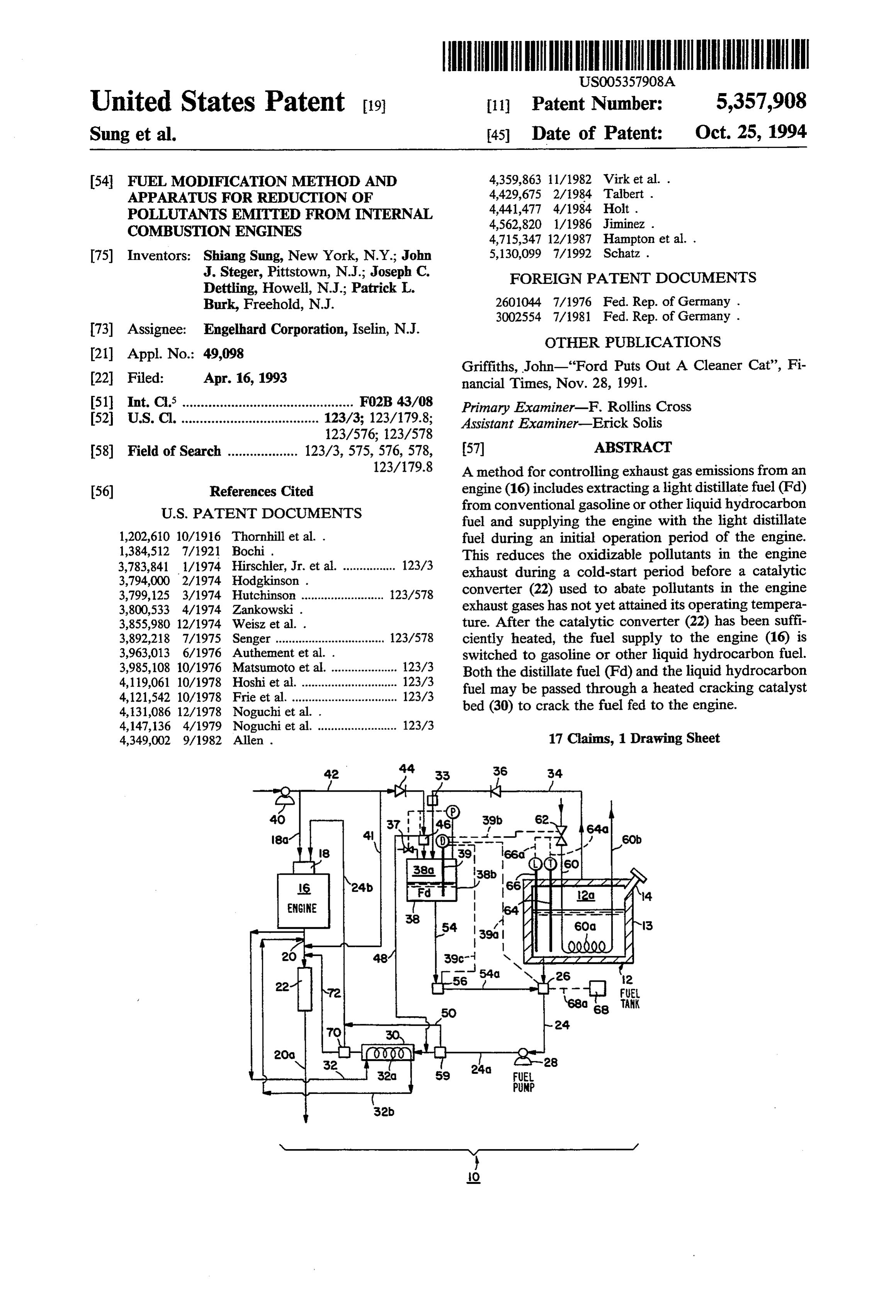
United States Patent (19) 11) Patent Number: 5,357,908 Sung et al. 45) Date of Patent: Oct. 25, 1994 (54) FUEL MODIFICATION METHOD AND 4,359,863 11/1982 Virk et al. . APPARATUS FOR REDUCTION OF 4,429,675 2/1984 Talbert . POLLUTANTS EMITTED FROM INTERNAL 4,441,477 4/1984 Holt . COMBUSTION ENGINES 4,562,820 1/1986 Jiminez .
I75 Inventors: Shiang Sung, New York, N.Y.; John 5,130,099 7/1992 Schatz . J. Steger, Pittstown, N.J.; Joseph C. FOREIGN PATENT DOCUMENTS
Dettling, Howell, N.J.; Patrick L.
Burk, Freehold, N.J. 2601044 7/1976 Fed. Rep. of Germany .
73) Assignee: Engelhard Corporation, Iselin, N.J. OTHER PUBLICATIONS
Griffiths, John-Ford Puts Out A Cleaner Cat', Fi 22) Filed: Apr. 16, 1993 nancial Times, Nov. 28, 1991. 51 int. C. .............................................. F02B 43/08 Primary Examiner-F. Rollins Cross (52) U.S.C. ..................................... 123/3; 123/179.8; Assistant Examiner-Erick Solis
58) Field of Search ................... 123/3, 575, 576, 578, 57 ABSTRACT 123/179.8 A method for controlling exhaust gas emissions from an (56) References Cited engine (16) includes extracting a light distillate fuel (Fd)
fuel and supplying the engine with the light distillate 1,202,610 10/1916 Thornhill et al. . fuel during an initial operation period of the engine. 1,384,512 7/1921 Bochi. This reduces the oxidizable pollutants in the engine 3,783,841 1/1974 Hirschler, Jr. et al................. 123/3 exhaust during a cold-start period before a catalytic 3,794,000 2/1974 Hodgkinson. converter (22) used to abate pollutants in the engine 3,799,125 3/1974 Hutchinson ......................... 123/578 3,800,533 4/1974 Zankowski. exhaust gases has not yet attained its operating tempera 3,855,980 12/1974 Weisz et al. . ture. After the catalytic converter (22) has been suffi 3,892,218 7/1975 Senger ................................. 123/578 ciently heated, the fuel supply to the engine (16) is 3,963,013 6/1976 Authement et al. . switched to gasoline or other liquid hydrocarbon fuel. 3,985,108 10/1976 Matsumoto et al. .................... 123/3 Both the distillate fuel (Fd) and the liquid hydrocarbon 4,119,061 10/1978 Hoshi et al. ............ fuel may be passed through a heated cracking catalyst 4,121,542 10/1978 Frie et al................................. 123/3 4,131,086 12/1978 Noguchi et al. . bed (30) to crack the fuel fed to the engine. 4,147,136 4/1979 Noguchi et al. ........................ 123/3 4,349,002 9/1982 Allen . 17 Claims, 1 Drawing Sheet
ENGINE
Page 2
Drawing sheet — no readable text.
Page 3
fractions of a fuel. See, e.g., U.S. Pats. Nos. 1,202,610;
FUEL MODIFICATION METHOD AND 1,384,512; 4,441,477; 3,800,533; 4,562,820; 3,963,013 and APPARATUS FORREDUCTION OF POLLUTANTS German Patent document DE 3002-544, dated Jul. 31, EMITTED FROM INTERNAL COMBUSTION 1981.
ENGINES
SUMMARY OF THE INVENTION
BACKGROUND OF THE INVENTION The present invention provides a method for abating 1. Field of the Invention pollutants discharged from an internal combustion en The present invention is concerned with an apparatus 10 gine fueled by a liquid hydrocarbon fuel, at least during for reducing the emission of pollutants in the exhaust the cold-start period of operation, by extracting low gas of an internal combustion engine by modifying the boiling point fraction of the liquid hydrocarbon fuel, fuel Supplied to the engine at least during a start-up and supplying the low boiling point fraction to the en period. More specifically, the present invention is con gine during start-up. Specifically, the method comprises cerned with both fractionation and catalytic treatment (a) heating the liquid hydrocarbon fuel to vaporize of conventional liquid hydrocarbon fuel used for an 15 therefrom a low boiling point fraction, condensing the internal combustion engine. low boiling point fraction to obtain therefrom a distill 2. Background and Related Art late fuel, and storing the distillate fuel in a storage con Apparatuses and techniques for modifying the fuel tainer;
fed to an internal combustion engine are known in the part of a(b)start-up supplying the distillate fuel to the engine as fuel/air combustion mixture for engine art. For example, U.S. Pat. No. 3,794,000 to Hodgkin start-up and during an initial engine operating period; son, dated Feb. 26, 1974 discloses a fuel system for and (c) after the initial engine operating period, termi separating volatile fuel from gasoline. The apparatus nating the supply of distillate fuel to the engine and used in this system comprises a vaporizing chamber into which gasoline is introduced to provide vapors which supplying the liquid hydrocarbon fuel of (a) to the en are removed by a pump and condensed under pressure 25 gine as part of a second fuel/air combustion mixture for to form a liquid which is stored in a storage container ther comprisesengine a subsequent
operating period. The method fur refining at least one of the distillate disposed within the vaporization chamber. The line from the pressurizing pump to the storage container is fuel and the liquid hydrocarbon fuel by contacting it extended around the storage container to provide addi under cracking or isomerizing conditions with a crack tional heat exchange with the gasoline (column 2, lines 30 ing catalyst prior to supplying the fuel to the engine, 54-55 and column 6, lines 30-31) thereby increasing and (e) regenerating the cracking catalyst during opera volatilization of the gasoline. When the engine is started tion of the engine by by-passing the supply of distillate the condensate is used as fuel. When the engine reaches fuel or liquid hydrocarbon fuel to the engine around the a satisfactory operating temperature, a valve cuts off the cracking catalyst, and flowing air through the cracking flow of the condensate and allows normal gasoline to 35 catalyst under catalyst regeneration conditions. flow to the carburetor (column 5, lines 13-20). The According to one aspect of the invention, one or both storage container for the condensate includes a level of refining of step (d) and regenerating of step (e) may sensor which, when the level of condensate is low, comprise heating the cracking catalyst, which may be triggers the pump to draw additional vapors from the accomplished using heat generated by operation of the vaporization chamber. When the vapor pressure in the engine and/or electrical power that may be generated vaporization chamber is low, additional gasoline is by the vehicle or that may come from a battery. drawn from the gas tank and sprayed into the vaporiza The method may further comprise carrying out step tion chamber (column 5, lines 35-44). In addition, when (a) by heating the liquid hydrocarbon fuel with heat the storage tank is full, the switch turns the condensing generated by operation of the engine. The use of heat pump off. After the cold-start period, gasoline from 45 both the gas tank and the volatile-depleted gasoline generated by the engine for this purpose or for steps (d) from the vaporization tank are used to run the engine ferring heatstated and (e) as from above may be accomplished by trans either or both of the engine exhaust (column 5, line 65 through column 6, line 15). gas and the engine coolant fluid to the liquid hydrocar U.S. Pat. No. 4,394,002 to Allen, dated Sep. 14, 1982, bon fuel. Alternatively, discloses an apparatus and a method for fractionating 50 tionally be replaced by the a heating in step (a) may op step which separates a low the gasoline fuel for an internal combustion engine, and boiling point fraction from the liquid hydrocarbon fuel combusting the different fractions in repeating sequence prior to condensing the low boiling point fraction. in the engine in order to improve fuel mileage. Heat from the engine is utilized via the engine coolant in the gasInisaflowed further aspect of this invention, when the exhaust through a heat exchanger in the gas tank
U.S. Pat. No. 3,855,980 to Weisz et al, dated Dec. 24, to heat the liquid hydrocarbon fuel, the exhaust gas is 1974 discloses a fuel system for an internal combustion preferably treated by the removal of pollutants such as engine in which conventional fuel from a fuel tank is unburned hydrocarbons, carbon monoxide or nitrogen passed through a zeolitic catalytic converter heated by oxides by contacting the exhaust gas under abatement engine exhaust gases before being supplied to the en 60 conditions with an exhaust gas purification catalyst, gine. The effect of the catalyst is said to improve the before flowing the exhaust gas into the heat exchanger. octane content of the fuel fed to the engine. Still another aspect of the invention comprises that U.S. Pat. No. 4,429,675 to Talbert, dated Feb. 7, 1984 the step of condensing the low boiling point fraction teaches the separation of conventional liquid fuel (gaso may comprise passing the low boiling point fraction in line) into a vapor fraction and a liquid fraction using 65 heat exchange relation with a heat exchanger utilizing either ultrasonic energy or the heat in the exhaust gases coolant from an air conditioning system powered by the of the engine. The heavier fraction is used, if at all, only vehicle. Alternatively, the condensing step may com at start-up. Other patents teach generally the use of light prise increasing the pressure in the storage container,
Page 4
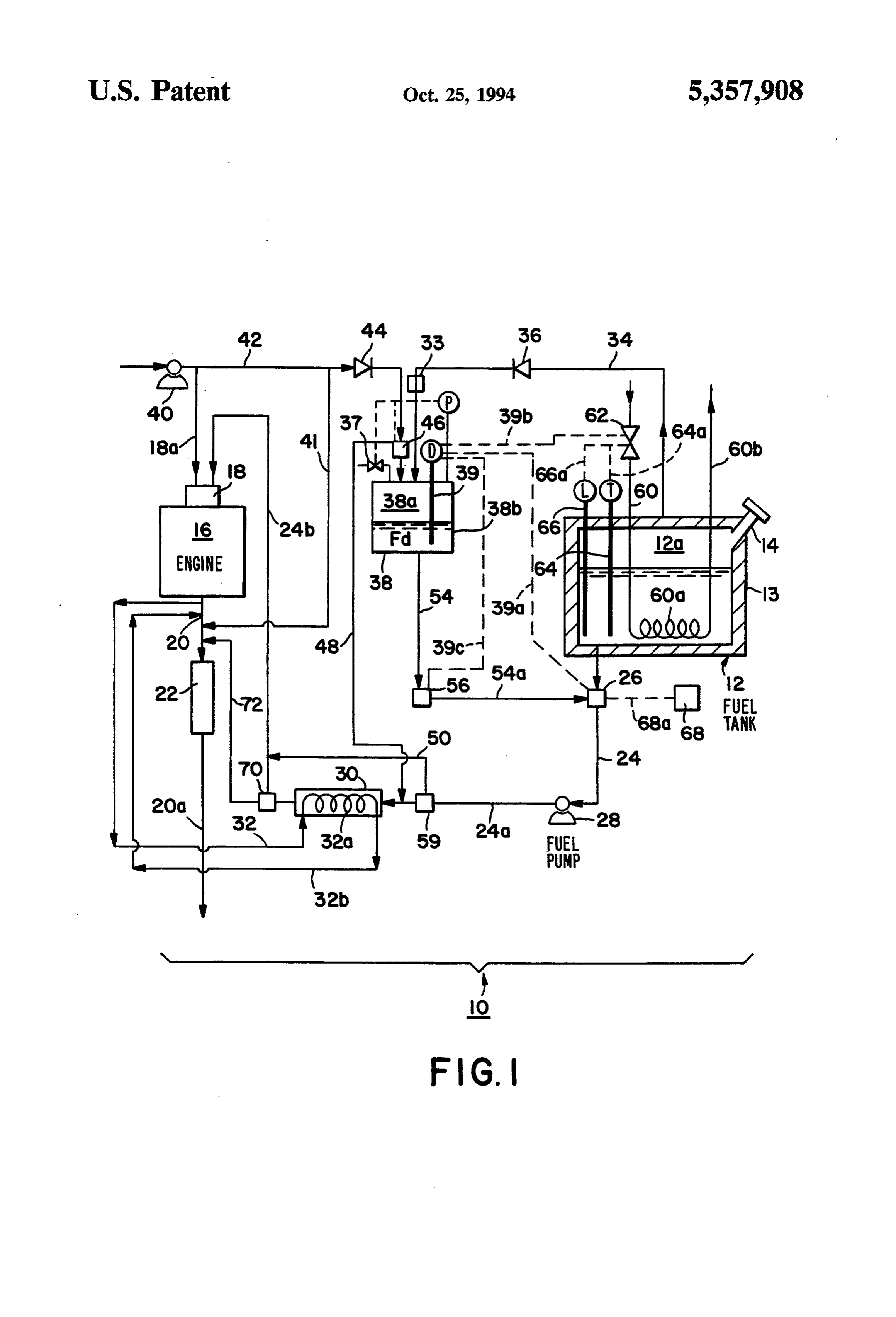
e.g., by introducing pressurized air into the storage when the temperature of the liquid hydrocarbon fuel container. reaches a predetermined level, the liquid fuel heating According to another aspect of the application, the means stops heating the fuel tank. According to yet method may comprise measuring the temperature of the another aspect of the invention, the apparatus may com liquid hydrocarbon fuel and ceasing the supply of heat 5 prise a fuel tank level sensing means, and the liquid fuel thereto when the temperature reaches a predetermined heating means may be responsive to the level sensing level. In addition, or as an alternative, the method may means, wherein when the level of the liquid hydrocar comprises measuring the quantity of liquid hydrocarbon bon fuel falls to a predetermined level, the liquid fuel fuel in the fuel tank and ceasing the supply of heat heating means stops heating the fuel tank. thereto when the quantity falls to a predetermined level. 10 BRIEF DESCRIPTION OF THE DRAWING In another aspect, the present invention provides an improvement in an internal combustion engine system FIG. 1 is a schematic block diagram illustrating one comprising an internal combustion engine, a fuel tank embodiment of an internal combustion engine system for storing a liquid hydrocarbon fuel, and a liquid fuel according to the present invention. transfer means including a fuel pump and a fuel line 15 DETAILED DESCRIPTION OF THE connecting the fuel tank in liquid flow communication INVENTION AND SPECIFIC PREFERRED with the engine for transferring the liquid fuel from the EMBODIMENTS THEREOF fuel tank to the engine, and an exhaust gas discharge pipe connected to the engine for discharge of exhaust FIG. 1 schematically illustrates an improved engine gas from the engine. The improvement comprises liquid system 10 in accordance with an embodiment of the fuel heating means disposed within the fuel tank to invention. The system includes a fuel tank 12 encased vaporize a low boiling point fraction from the liquid with a layer of thermal insulating material 13 and hav hydrocarbon fuel, and a vapor line connecting the fuel ing a fill pipe 14 fitted with a cap. Fuel tank 12 is con tank in vapor flow communication with a condenser nected, as described below, to supply fuel to an internal Zone for condensing the low boiling point fraction into 25 combustion engine 16 fitted with a carburetor (or fuel a liquid distillate fuel. The improvement further com injector) 18 having an air inlet 18a. In the illustrated prises a distillate fuel storage container connected in embodiment, engine 16 has an exhaust pipe 20, 20a fitted liquid flow communication with the condenser zone, with a conventional catalytic converter 22 which con and a distillate fuel line connecting the distillate fuel tains a catalyst for the abatement of pollutants. For storage container in liquid flow communication with 30 example, in the case of a gasoline-fueled engine, cata the fuel line. A distillate fuel control valve may be dis lytic converter 22 may serve to catalyze the conversion posed in the distillate fuel line to control the flow of of hydrocarbons, carbon monoxide and nitrogen oxides distillate fuel therethrough. A liquid fuel control valve contained in the exhaust gas to H2O, CO2 and N2. is disposed in the fuel line to selectively control the flow Liquid fuel transfer means is provided by a fuel line of fuel through the fuel line from the fuel tank or the 35 24, 24a, 24b which extends from fuel tank 12 to carbure distillate fuel line. There may also be a control means tor 18 and in which is disposed a solenoid-operated responsive to start-up of the engine and operationally valve 26, a fuel pump 28, valve 59, a cracking catalyst connected to both the liquid fuel control valve and the bed 30 and a valve 70. Preferably, valve 59 and valve 70 distillate fuel control valve, to open the distillate fuel are both solenoid-operated valves. Cracking catalyst valve and operate the liquid fuel control valve to permit bed 30 contains a cracking catalyst, for example, a solid the flow of liquid distillate fuel into the fuel line during super acid catalyst such as ZrO2:SO4 which is capable an initial engine operating period, and to close the distil of refining liquid hydrocarbon fuels such as gasoline at late fuel valve and operate the liquid fuel valve to per room temperature in order to crack heavier molecules mit the flow of liquid hydrocarbon fuel therethrough at to lighter molecules and optionally to isomerize certain the end of the initial engine operating period. The appa 45 molecules to form an improved fuel which is more ratus may further comprise a cracking catalyst bed readily combusted in the engine and which permits disposed in the fuel line for refining fuel flowing there leaner operation. Depending on the type of catalyst through into a more efficiently combustible composi used and the extent and rate of cracking desired, it may tion and regeneration means for regenerating the crack be desirable to heat cracking catalyst bed 30. This may ing catalyst while the engine is in operation. 50 be effectively accomplished by diverting at least a por According to one aspect of the invention the im tion of the hot exhaust gas exiting from engine 16 via provement may further comprise a fuel by-pass line exhaust pipe 20 into line 32. The hot exhaust gases disposed in the fuel line, through which fuel flowing to would then flow through a coil 32a disposed within the engine by-passes the cracking catalyst bed. cracking catalyst bed 30 to heat catalyst bed 30. The In another aspect of the invention, the improvement 55 exhaust gas is then withdrawn via line 32b to pipe 20 for further comprises an exhaust gas catalytic converter discharge through catalytic converter 22. In other en positioned in the exhaust gas pipe in gas flow communi bodiments, a plate-type heat exchanger may be used in cation with exhaust gas discharged therethrough to place of coil 32a to heat catalyst bed 30. Alternatively, catalyze the conversion of noxious components of the catalyst bed 30 could be heated by an electrical resis exhaust gas to innocuous components. The liquid fuel tance heater powered from the vehicle battery. heating means may be dimensioned and configured to A vapor line 34 connects the vapor space 12a above transfer heat from the effluent of the exhaust gas cata the gasoline (or other liquid hydrocarbon fuel contained within fuel tank 12) with a condenser 38 which is lytic converter to the liquid hydrocarbon fuel in the fuel tank. equipped with a distillate fuel level sensor 39 having According to another aspect of the invention, the 65 associated therewith a sending unit D connected by a apparatus may further comprise fuel tank temperature first control line 39a to valve 26, by a second control sensing means, and the liquid fuel heating means may be line 39b to valve 62, and also by a third control line 39c responsive to the temperature sensing means, wherein to valve 56. Valves 26, 62 and 56 are all preferably
Page 5
solenoid-operated control valves. Vapor line 34 is pro from fuel tank 12. As a consequence of heating the vided with a check valve 36 to ensure that there is no gasoline or other liquid hydrocarbon fuel stored in fuel backflow from condenser 38 to the fuel tank 12. An air tank 12, a low boiling fraction of hydrocarbons from the pump 40 provides compressed air through line 42 liquid hydrocarbon fuel contained within fuel tank 12 is through a check valve 44 and valve 46 which is prefera vaporized and passes through vapor line 34, through bly a solenoid-operated valve, into the vapor space 38a check valve 36 and heat exchanger 33, and into con above condensed distillate fuel Fd contained within the denser 38. If the temperature of the gasoline within fuel distillate fuel storage container 38b provided, in the tank 12 becomes too high, sending unit T of tempera illustrated embodiment, by the bottom portion of con ture probe 64 sends a signal through control line 64a to denser 38. A compressed air by-pass line 48 extends 10 close valve 62 to reduce or stop altogether the in-flow from valve 46 to fuel line 24a, for a purpose to be de of heating fluid. Should the level, i.e., quantity, of fuel in scribed below. Air pump 40 may also provide com fuel tank 12 become exceedingly low, fuel level sensor pressed air to carburetor 18 via air inlet 18a. Alterna 66 emits a signal from its sending unit L through control tively, or in addition, air pump 40 may provide com line 66a to move valve 62 in a closing direction to re pressed air through line 41 to exhaust pipe 20 for entry 15 duce or eliminate the flow of heating fluid. into catalytic converter 22. Valves (not shown) control Heat exchanger 33 withdraws heat from the vapor the air flow into air inlet 18a and/or exhaust pipe 20. flowing in vapor line 34 to promote condensation of the A fuel line by-pass conduit 50 is connected to valve distillate fuel in condenser 38, which then collects in 59 which is disposed in fuel line 24a at a point upstream distillate fuel storage container 38b. Heat exchanger 33 of cracking catalyst bed 30 and runs to fuel line 24b at a 20 may be a plate-type heat exchanger which may utilize point downstream of cracking catalyst bed 30, provid coolant from the vehicle air conditioning system. Com ing a by-pass in the fuel line around catalyst bed 30. pressed air may be introduced into condenser 38 by A distillate fuel line 54 leads from the distillate fuel compressed air pump 40 via line 42 through check valve storage container 38b to a solenoid-operated valve 56, 44 and valve 46 to facilitate condensation within con from whence distillate fuel line 54a runs to solenoid 25 denser 38 by increasing the pressure therein. Any other operated valve 26. Distillate fuel from storage container suitable expedient may be employed to facilitate con 38b can thus be flowed into the liquid fuel transfer densation of the vapor within condenser 38, as by equip means through valve 26, for transfer to carburetor 18 ping the exterior of condenser 38 with cooling fins (not via fuel line 24, fuel pump 28 and fuel line 24a, valve 59 shown), using a condensation coil driven by the vehicle and either through catalyst bed 30 and valve 70 or by 30 air conditioning system; using a fan to provide air-cool pass conduit 50, and thence via fuel line 24b into carbu ing, etc.
retor 18. A timer 68 is connected by a control line 68a Condenser 38 is equipped with a pressure regulator P to valve 26. and a vent valve 37. When the pressure in condenser 38 Fuel tank 12 is equipped with a heating fluid inlet 60, rises to a point at which the flow of vapor from tank 12 heating coil 60a and heating fluid outlet 60b. Any suit 35 through vapor line 34 is inhibited, regulator P opens able heating fluid, e.g., the coolant liquid used to cool vent valve 37 to reduce the pressure in condenser 38. A internal combustion engine 16, may be used. Thus, in a vent line (not shown) runs from valve 37 to fuel tank12 typical automobile engine, a side stream of heated en to return vented distillate vapors back into fuel tank 12. gine coolant would be passed from the radiator into The pressure regulator P also controls valve 46 so that heating fluid inlet 60 and after passing through coil 60a the pressure in the condenser 38 can be maintained at a would be returned to the engine radiator via outlet 60b. preset minimal level, e.g. 5 psi, by the addition of air However, a plate-type heat exchanger would be pre from air pump 40.
ferred over coil 60a. Alternatively, or in addition, a It will be apparent that distillate fuel Fd will thus heating fluid other than the engine coolant fluid could accumulate within the storage container 38b of con be used. The separate heating fluid could be heated by 45 denser 38 when heated fluid passes through heating coil heat exchange with hot exhaust gas discharged from 60a, or that the system may be "primed” by providing engine 16 or from catalytic converter 22. In still another an appropriate quantity of a light distillate fuel Fd in the embodiment, hot and preferably catalytically treated storage container 38b. In any case, upon the starting of exhaust gas from the engine may be flowed through the the engine, if distillate fuel level sensor 39 indicates the heat exchanger to heat the liquid fuel. Heating fluid 50 presence of an adequate supply of liquid distillate fuel, inlet 60 is equipped with a control valve 62 to control sending unit D emits a signal via signal control line 39a the flow of heating fluid through coil 60a. A tempera to valve 26 to close off the flow of liquid fuel from fuel ture probe 64 and fuel level sensor 66 are mounted tank 12 to fuel pump 28 and emits a signal via signal within fuel tank 12. Temperature probe 64 is equipped control line 39c to open valve 56 to the flow of distillate with a sending unit T and fuel level sensor 66 is 55 fuel from storage container 38b via line 54 and 54a to equipped with a sending unit L which emits a signal valve 26 as long as there is an adequate supply of liquid indicating the quantity of liquid hydrocarbon fuel in the distillate fuel in storage container 38b. The distillate fuel fuel tank. Sending units T and L are connected via then flows to the engine through the liquid fuel transfer control lines 64a and 66a, respectively, to provide con means, i.e., through fuel line 24, pump 28, fuel line 24a, trol signals to control valve 62. 60 valve 59, and through catalyst bed 30 or by-pass 50 to In operation, distillate fuel level sensor 39, sensing a fuel line 24b, into carburetor 18, wherein it is mixed low level or entire lack of distillate fuel in the distillate with air introduced via air inlet 18a to provide a start-up fuel storage container 38b, prompts sending unit D to fuel/air combustion mixture for engine start-up. If there send a signal via control line 39b to cause control valve is not an adequate supply of liquid distillate fuel in stor 62 to open, thereby permitting the flow of a heating 65 age container 38b, fuel is drawn from tank 12 as de fluid through heating fluid inlet 60, heating coil 60a and scribed below. Heating means may be provided to heat thence out of fuel tank 12 through heating fluid outlet catalyst bed 30 to improve its conversion performance, 60b. Insulation material 13 serves to reduce heat losses e.g., a side stream of hot exhaust gases may be drawn
Page 6
directly from the engine exhaust gas manifold and sensor or other control device, as discussed above) and passed through line 32, coil 32a and line 32b, to heat switches the valve to supply the engine 16 with fuel catalyst bed 30, or a heating coil powered through the from fuel tank 12. However, storage container 38b will vehicle's electrical system may be used to heat catalyst be sized to hold a quantity of distillate fuel projected to bed 30. be adequate to start the engine until normal engine The period of time during which engine 16 is supplied operation replenishes the supply by vaporizing the liq with the distillate fuel Fd from storage container 38b uid hydrocarbon fuel in tank 12. The light distillate fuel may be determined by timer 68 which sends a signal via will thus be continuously replenished by vapor evapo timer signal line 68a to solenoid-operated valve 26. The rated from the fuel in tank 12 as described above. There timer signal may allow valve 26 to open for the flow of 10 fore, an ample supply of distillate fuel Fd should be liquid distillate fuel according to signals received from available at all times for any reasonable duration of the sending unit D for a predetermined period of time after initial operating periods.
engine start-up, for example, two minutes, after which Regeneration of cracking catalyst bed 30 will be re time the engine can be expected to combust the liquid quired from time to time. Generally, regeneration may hydrocarbon fuel more efficiently. Alternatively, a tem 15 be achieved by providing sufficient oxygen in the gas perature sensor (not shown) may be used to hold valves flowed through catalyst bed 30 at a sufficiently high 26 and 56 in position to supply distillate fuel Fd to en temperature, to oxidize carbonaceous deposits which gine 16 (subject to the availability of such fuel as indi tend to accumulate on the cracking catalyst during use. cated by sending unit D) until the engine attains a pre Heating coil 32a supplies heat during regeneration in determined operating temperature which may be indi 20 the same manner as it does during cracking operation, as cated by the temperature of the engine exhaust gas described above. Therefore, it is preferred to regenerate manifold. In yet another alternative, or in addition, catalyst bed 30 when the exhaust gases are hot, i.e., after temperature sensors may sense the temperature of the the initial cold-start period of operation and while the exhaust gas fed to the catalytic converter 22 or the engine is running on liquid hydrocarbon fuel from fuel temperature of the catalytic converter 22 itself, and use 25 tank 12. During regeneration, the flow fuel by-passes such temperature to determine the period for which catalyst bed 30 via by-pass line 50 as described below. valve 26 allows distillate fuel Fd to be fed to engine 16. Regeneration is initiated by a regeneration signal from a During this initial period of operation, e.g., about the regeneration control means (not shown) at timed inter first two minutes of operation, the engine is thus sup vals or when a sensor indicates that the catalyst in bed plied with a light distillate fuel Fd which has been 30 30 is not operating effectively. Preferably, regeneration cracked by treatment in catalyst bed 30 to provide a fuel is performed during extended periods of operation and which is rapidly ignitable and which may be efficiently for this reason, the regeneration control means may combusted in a lean fuel/air mixture. These factors comprise a mechanism controlled by the vehicle opera greatly reduce the amount of hydrocarbon pollutants tor at appropriate times. Upon receipt of the initiation emitted in the exhaust gas during the initial period of 35 signal, valve 59 closes off the flow of fuel through cata engine operation. This is of great benefit because during lyst bed 30 and directs the fuel through by-pass line 50, this initial period the catalytic converter 22 is cold, i.e., and then to the engine via line 24b as before. In addition, it has not yet attained its normal operating temperature valve 46 admits compressed air from compressed air range, and is therefore much less efficient in catalyzing pump 40 and line 42 into line 48 for introduction into the oxidation of hydrocarbons and carbon monoxide fuel line 24a, in order to pass combustion air through than it is when it has been heated to a temperature catalyst bed 30 to oxidize carbonaceous deposits accu within its normal operating range, e.g., from about 300 mulated on the cracking catalyst contained therein, and to 800° C. Thus, hydrocarbon emissions are signifi thereby regenerate the catalyst.
cantly reduced during the critical initial cold-start per During regeneration, solenoid-operated valve 70 is iod despite the inactivity of the catalytic converter. 45 positioned to isolate the effluent of catalyst bed 30 from After the predetermined time has lapsed, or the pre carburetor 18 and to admit the discharged regeneration determined engine exhaust gas or pollution abatement products emerging from catalyst bed 30 via line 72 into catalyst temperature has been attained, timer 68 or an exhaust pipe 20 at a point upstream of catalytic con other appropriate control mechanism switches valve 26 verter 22 so that the regeneration by-products are to stop the flow of distillate fuel Fd from storage con 50 treated in catalytic converter 22. tainer 38b and to begin the flow of the liquid hydrocar Generally, it will be observed that the embodiment of bon fuel, e.g., gasoline, from fuel tank 12 to engine 16 the invention illustrated in FIG. 1 provides for continu via the liquid fuel transfer means described above. En ous replenishment of the distillate fuel Fd by vaporiza gine 16 is thus supplied with the gasoline or other liquid tion of the gasoline or other hydrocarbon liquid fuel hydrocarbon fuel stored in fuel tank 12 for a subsequent 55 contained in fuel tank 12 and condensation of light dis engine operating period following the initial engine tillate fuel therefrom within condenser 38. This light operating period. The gasoline or other liquid fuel re distillate fuel is utilized during an initial cold-start en maining in fuel tank 12 may be considered enriched in gine operating period to thereby reduce the emission of octane depending on the amount of fuel of low boiling hydrocarbon pollutants at least until the catalytic con point fraction which has been removed therefron. Pref. verter 22 has reached its normal operating temperature erably, the subsequent engine operating period begins and thereby its usual operating efficiency. The light after the catalytic converter has been heated to within distillate fuel Fd may be further enhanced by being its normal operating temperature range. cracked/isomerized by being passed through the crack As discussed above, should the level of distillate fuel ing catalyst contained in catalyst bed 30. After a prede Fol contained in storage container 38b drop to a prede 65 termined period of initial engine operation, controlled termined level deemed to be inadequate, distillate fuel either by a timer or by sensing the temperature of the level sensor 39 sends a signal via control line 39a to engine or the exhaust or the catalytic converter (22 in valve 26 which pre-empts timer 68 (or a temperature the illustrated embodiment) temperature, the fuel sup
Page 7
ply is switched to the conventional gasoline or other 10. The method of claim 1 further comprising mea liquid hydrocarbon fuel contained in fuel tank 12. This suring the temperature of the liquid hydrocarbon fuel fuel is passed through the cracking catalyst bed (30 in and ceasing the supply of heat thereto when the temper the illustrated embodiment) to provide a cleaner burn ature reaches a predetermined level. ing fuel for the subsequent engine period of operation. 11. The method of claim 1 wherein condensing the While the invention has been described in detail with low boiling point fraction in step (a) comprises increas respect to specific preferred embodiments thereof, it ing the pressure in the storage container. will be appreciated upon a reading and understanding of 12. The method of claim 1 or claim 10 further con the foregoing that numerous variations may be made to prising measuring the quantity of the liquid hydrocar those embodiments which nonetheless lie within the O bon fuel and ceasing the supply of heat thereto when the spirit and scope of the appended claims. quantity falls to a predetermined level. What is claimed is: 13. In an internal combustion engine apparatus com 1. A method for abating pollutants in the exhaust gas prising an internal combustion engine having a fuel discharged from an internal combustion engine fueled intake, a fuel tank for storing a liquid hydrocarbon fuel by a liquid hydrocarbon fuel, the method comprising: 5 and a liquid fuel transfer means including a fuel pump (a) heating the liquid hydrocarbon fuel to vaporize and a fuel line connecting the fuel tank in liquid flow therefrom a low boiling point fraction, condensing communication with the engine for transferring the the low boiling point fraction to obtain therefrom a liquid fuel from the fuel tank to the engine, and an ex distillate fuel, and storing the distillate fuel in a haust gas discharge pipe connected to the engine for storage container; discharge of exhaust gas from the engine, the improve (b) supplying the distillate fuel to the engine as part of ment comprising:
a start-up fuel/air combustion mixture for engine (a) liquid fuel heating means disposed within the fuel start-up and during an initial engine operating per tank to vaporize a low boiling point fraction from iod; the liquid hydrocarbon fuel; (c) after the initial engine operating period, terminat 25 (b) a vapor line connecting the fuel tank in vapor flow ing the supply of distillate fuel to the engine and communication with a condenser zone for con supplying the liquid hydrocarbon fuel of (a) to the densing the low boiling point fraction into a liquid engine as part of a second fuel/air combustion distillate fuel;
mixture for a subsequent engine operating period; (c) a distillate fuel storage container connected in (d) refining at least one of the distillate fuel and the 30 flow communication with the condenser Zone; liquid hydrocarbon fuel by contacting it under (d) a distillate fuel line connecting the distillate fuel cracking or isomerizing conditions with a cracking storage container in liquid flow communication catalyst prior to supplying the fuel to the engine; with the fuel line and having a distillate fuel control and valve disposed therein to selectively control the (e) regenerating the cracking catalyst during opera 35 flow of distillate fuel thereto; tion of the engine by by-passing the supply of distill (e) a liquid fuel control valve disposed in the fuel line late fuel or liquid hydrocarbon fuel to the engine to selectively control the flow of fuel from the fuel around the cracking catalyst, and flowing air tank or the distillate fuel line through the fuel line; through the cracking catalyst under catalyst regen (f) control means responsive to start-up of the engine eration conditions. 40 and operatively connected to the liquid fuel control 2. The method of claim 1 wherein at least one of valve and to the distillate fuel control valve to open refining of step (d) and regenerating of step (e) com the distillate fuel control valve and operate the prises heating the cracking catalyst. liquid fuel control valve to permit the flow of liq 3. The method of claim 2 wherein heating the crack uid distillate fuel into the fuel line during an initial ing catalyst comprises using heat generated by opera 45 engine operating period and to close the distillate tion of the engine. fuel valve and operate the liquid fuel control valve 4. The method of claim 2 wherein heating the crack to permit the flow of liquid hydrocarbon fuel ing catalyst comprises using electrical power. through the fuel line at the end of the initial engine 5. The method of claim 1 including carrying out step operating period;
(a) by heating the liquid hydrocarbon fuel with heat 50 (g) a cracking catalystbed disposed in the fuel line for generated by operation of the engine. converting fuel flowing therethrough into a more 6. The method of claim 3 or claim 5 wherein using efficiently combustible composition; and heat generated by operation of the engine comprises (h) regeneration means for regenerating the cracking taking heat from the engine exhaust gas. catalyst while the engine is in operation. 7. The method of claim 3 or claim 5 wherein using 55 14. The apparatus of claim 13 further comprising fuel heat generated by operation of the engine comprises by-pass means disposed in the fuel line through which taking heat from the engine coolant fluid. fuel flowed to the engine intake through the fuel line 8. The method of claim 1 wherein condensing the low by-passes the cracking catalyst bed.
boiling point fraction in step (a) comprises passing the 15. The apparatus of claim 13 further comprising an low boiling point fraction in heat exchange relation exhaust gas catalytic converter positioned in the ex with a heat exchanger utilizing coolant from an air haust gas discharge pipe in gas flow communication conditioning system powered by the vehicle engine. with exhaust gas discharged therethrough to catalyze 9. The method of claim 6 further comprising treating the conversion of noxious components of the exhaust the exhaust gas discharged by the engine to abate the gas to innocuous components, and wherein the liquid pollutants content of the exhaust gas by contacting the 65 fuel heating means is dimensioned and configured to exhaust gas under abatement conditions with an exhaust transfer heat from the effluent of the exhaust gas cata gas purification catalyst before using the exhaust gas to lytic converter to the liquid hydrocarbon fuel in the fuel heat the liquid hydrocarbon fuel. tank.
Page 8
16. The apparatus of claim 13 or claim 15 further comprising fuel tank level sensing means and wherein comprising fuel tank temperature sensing means and wherein the liquid fuel heating means is responsive to the liquid fuel heating means is responsive to the level the temperature sensing means, wherein when the tem sensing means, wherein when the level of the liquid perature of the liquid hydrocarbon fuel reaches a prede hydrocarbon fuel falls to a predetermined level, the termined level, the liquid fuel heating means stops heat liquid fuel heating means stops heating the fuel tank. ing the fuel tank.
17. The apparatus of claim 13 or claim 15 further k k
Provenance
- Collection
- Cited prior art
- Original PDF
- patentimages.storage.googleapis.com →
- Filed
- 1993-04-16
- Pages
- 8
- Method
- pdftotext (the PDF's own text layer) + pdftoppm 300dpi page scans
- Source
- Google Patents bibliographic record
- Granted
- 1994-10-25
- Inventors
- Shiang Sung; John J. Steger; Joseph C. Dettling; Patrick L. Burk; Engelhard Corp
- Transcribed from
- patentimages.storage.googleapis.com →