patent · US5997283
Electrolysis systems
7 December 1999
Page 1 — bibliographic record
United States Patent (19) 11 Patent Number: 5,997.283 Spiros (45) Date of Patent: Dec. 7, 1999 54 ELECTROLYSIS SYSTEMS 3,567,399 3/1971 Altmann et al. ........................ 110/213 3.843,329 10/1974 Longley ...... ... 110/213 75 Inventor: Spiro Ross Spiros, Mascot, Australia 4.014,777 3/1977 Brown ..................................... 431/354 4,145,979 3/1979 Lilley et al. ............................ 110/214 (73) Assignee: Hydrogen Technology Ltd, Mascot, 5,249,952 10/1993 West et al. .............................. 431/350 Australia 5,310,334 5/1994 Spiros.
5,366,699 11/1994 Milfeld et al. .............................. 431/5 21 Appl. No.: 09/100,236 5,843,292 12/1998 Spiros ..................................... 204/258
Primary Examiner-Carl D. Price
Related U.S. Application Data Attorney, Agent, or Firm- Pillsbury Madison & Sutro LLP 62 Division of application No. 08/610,968, Mar. 5, 1996, Pat. 57 ABSTRACT No. 5,843,292, which is a continuation of application No.
PCT/AU94/00532, Sep. 6, 1994. A cell arrangement for the electrolysis of water to liberate 30 Foreign Application Priority Data hydrogen and oxygen gases is described. A cell unit (125) Sep. 6, 1993 AU Australia ................................ PM1054 has a Stacked arrangement of Segmentation disks (114), a
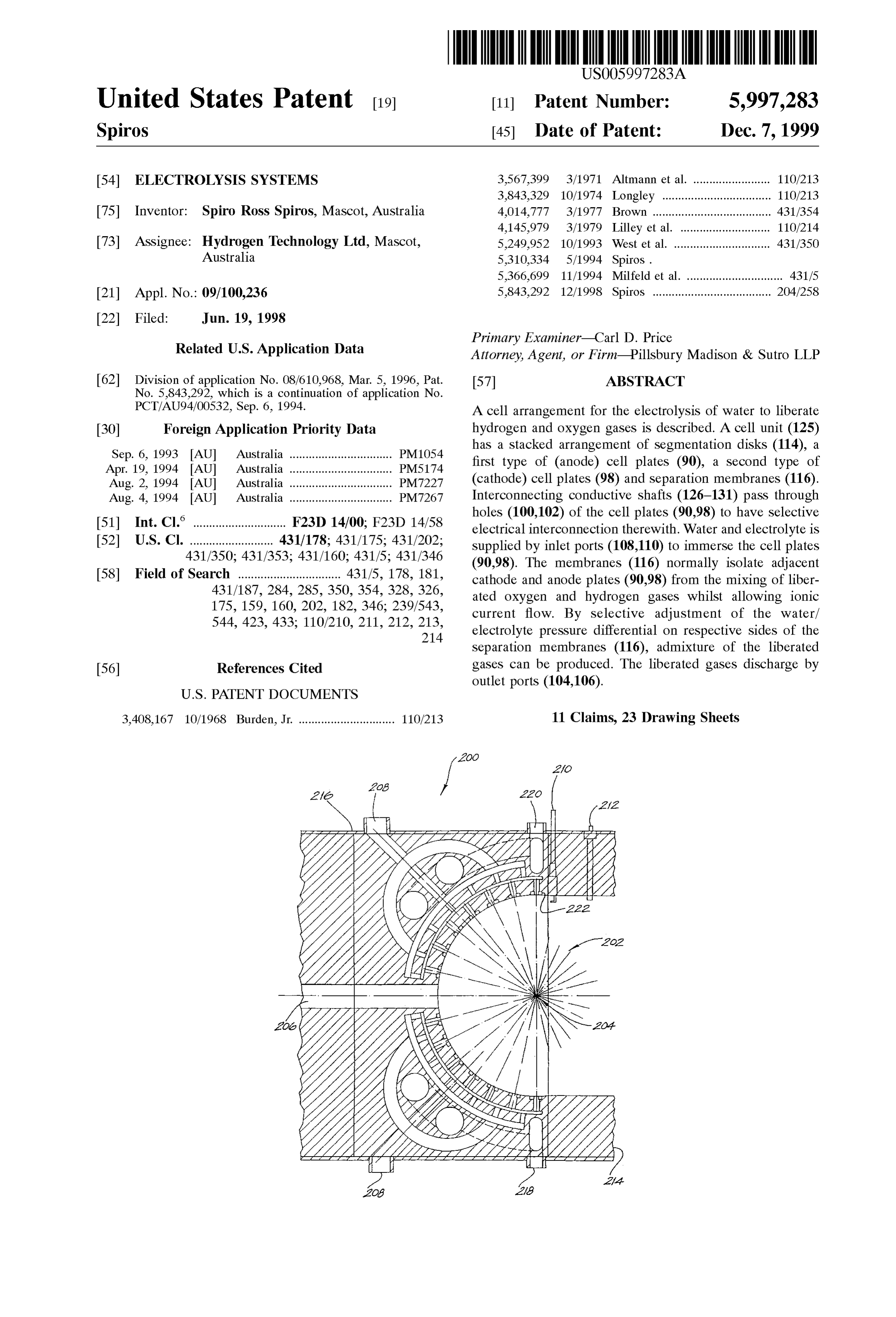
Apr. 19, 1994 AU Australia ...... ... PMS.174 first type of (anode) cell plates (90), a second type of Aug. 2, 1994 AU Australia ...... ... PM/227 (cathode) cell plates (98) and separation membranes (116). Aug. 4, 1994 AU Australia ................................ PM7267 Interconnecting conductive shafts (126-131) pass through 51 Int. CI. . ... F23D 14/00, F23D 14/58 holes (100,102) of the cell plates (90.98) to have selective electrical interconnection therewith. Water and electrolyte is 52 U.S. Cl. .......................... 431/178; 431/175; 431/202; supplied by inlet ports (108.110) to immerse the cell plates 431/350; 431/353; 431/160; 431/5; 431/346 (90.98). The membranes (116) normally isolate adjacent 58 Field of Search ................................ 431/5, 178, 181, cathode and anode plates (90.98) from the mixing of liber 431/187, 284, 285, 350, 354, 328,326, ated oxygen and hydrogen gases whilst allowing ionic 175, 159, 160, 202, 182, 346; 239/543, current flow. By selective adjustment of the water/ 544, 423, 433; 110/210, 211, 212, 213, electrolyte pressure differential on respective sides of the 214 separation membranes (116), admixture of the liberated 56) References Cited gases can be produced. The liberated gases discharge by
3,408,167 10/1968 Burden, Jr. .............................. 110/213 11 Claims, 23 Drawing Sheets
Page 2
Drawing sheet — no readable text.
Page 3
Drawing sheet — no readable text.
Page 4
Drawing sheet — no readable text.
Page 5
Drawing sheet — no readable text.
Page 6
Drawing sheet — no readable text.
Page 7
Drawing sheet — no readable text.
Page 8
Drawing sheet — no readable text.
Page 9
Drawing sheet — no readable text.
Page 10
Drawing sheet — no readable text.
Page 11
Drawing sheet — no readable text.
Page 12
Drawing sheet — no readable text.
Page 13
Drawing sheet — no readable text.
Page 14
Drawing sheet — no readable text.
Page 15
Drawing sheet — no readable text.
Page 16
XXKXXXX XXXXXKXXXXXXXXXXXXXXX 3.
s NNNNNNR,
S. 5 ZZZZZZZZéz
rtyver ketov-Vyver 9-treets
xxxx xxxx xxxxx 23222232 s
& XXXXYKXXXXXXXXXXXX XXXX
SN SSSÉSES
ZZZZZZZZZZZZZZZZZZZ
EazZZZZZZ S xxxxxxx
SNNNNN
XXXX XXX XXXX XXXYK 2
ZZZZZ
NNNNNNN i S
Sixx xxxxxxx
Page 17
Drawing sheet — no readable text.
Page 18
NSN NSWNNNNN
SNNNNNNNNNN
YYYYYYYYYYY
UNNYSNNNNNYS
SSSSSSSYYYY
SNYaYaNSYYYYY 5 A6
SwNYSwSYNSNYNYNYNWYSa NV
SNYSYYYYTSSS
Cs as area as as r WNWNYWNX
N S SSR Za
NYNNyyyyyy
ZZZYZZYYYY
ZZZZAZZZZZZZZZZZZZZZZZZZZZZZZZZZZY 7
Page 19
Drawing sheet — no readable text.
Page 20
Drawing sheet — no readable text.
Page 21
Drawing sheet — no readable text.
Page 22
Drawing sheet — no readable text.
Page 23
Drawing sheet — no readable text.
Page 24
Drawing sheet — no readable text.
Page 25
ELECTROLYSIS SYSTEMS trically connected in Series. The end result is a large Structure to be Supported.
This is a division of application Ser. No. 08/610,968, It is also not possible to produce high gas flow rates (of filed Mar. 5, 1996, which issued and which was a continu the order of 10,000 liters per hour) on demand from the prior ation of International application No. PCT/AU94/00532 art apparatus without the use of expensive and complicated filed Sep. 6, 1994 now U.S. Pat. No. 5,843,292. equipment, and even then the equipment Suffers from low
TECHNICAL FIELD OF THE INVENTION
efficiencies in the conversion of electrical energy to generate the hydrogen and oxygen gases. Thus the large Scale com
The present invention relates to the generation of hydro mercial implementation of Such apparatus is not economi gen gas and oxygen gas from water, either as an admixture cally viable.
or as Separated gases, by the process of electrolysis, and Admixed hydrogen and oxygen gases (or hydroxy gas) relates further to applications for the use of the liberated gas. are used as a thermal Source when burnt in a stream, for Embodiments of the invention particularly relate to appara example, in furnaces. Hydrogen alone is used for atomic tus for the efficient generation of these gases, and to use of 15 cutting and often for atomic welding, although the device the gases as a thermal Source in atomic welding or cutting, described in the Brown patent performed atomic welding and in gaseous waste disposal. with admixed hydrogen and oxygen. Recent industry prac tice clearly exemplifies that the presence of oxygen in a
BACKGROUND ART plasma arc causes Severe oxidation of the tungsten elec The technique of electrolysing water in the presence of an trodes.
electrolyte such as sodium hydroxide (NaOH) or potassium One of the problems experienced in implementing these hydroxide (KOH) to liberate hydrogen and oxygen gas (H, applications is the need to incorporate electrical Switchgear O) is well known. The process involves applying a DC to transform mains Supply Voltages to a level Suitable for a potential difference between two or more anode/cathode bank of electrolysis cells (i.e. by Step-down transformers). electrode pairs and delivering the minimum energy required The resulting completed arrangement is inefficient electri to break the H-O bonds (i.e. 68.3 kcal per mole (a STP). 25 cally and cumberSome, and also can be expensive if precise The gases are produced in the Stoichiometric proportions for voltage and current regulation (hence gas flow regulation) is O:H of 1:2 liberated respectively from the anode (+) and required.
cathode (-). Combusted hydrogen and oxygen gases mixed into a Reference can be made to the following texts: “Modern Single Stream burn at a very high temperature, typically of Electrochemistry, Volume 2, John O’M. Bockris and Amu the order of 6000 C. Hydrogen/oxygen welding sets are lya K. N. Reddy, Plenum Publishing Corporation”, “Electro generally known to comprise of a welding tip or hand piece Chemical Science, J. O’M. Bockris and D. M. Drazic, Taylor connected by a dual gas hose to Separate Supplies of oxygen and Francis Limited' and “Fuel Cells, Their and hydrogen.
Electrochemistry, J. O’M. Bockris and S. Srinivasan, 35 There are four other common types of welding apparatus McGraw-Hill Book Company'. and techniques in use; these are oxy-acetylene welding, A discussion of experimental work in relation to elec electric arc welding, MIG (metal-inert-gas)/TIG (tungsten trolysis processes can be obtained from "Hydrogen Energy, inert-gas) Systems and plasma cutting.
Part A, Hydrogen Economy Miami Energy Conference, It is estimated that more than 100,000 oxy-acetylene sets Miami Beach, Fla., 1974, edited by T. Nejat Veziroglu, 40 are used in Australia. Of those, approximately 70% are used Plenum Press”. The papers presented by J. O’M. Bockris on primarily for the cutting of metals, with the remainder being pages 371 to 379, by F. C. Jensen and F. H. Schubert on used as a heat Source, for fusion welding of sheet metal, pages 425 to 439 and by John B. Pangborn and John C. brazing, Silver Soldering and the like. Typically oxy Sharer on pages 499 to 508 are of particular relevance. acetylene Sets can Weld thicknesses of metal between 0.5 On a macro-Scale, the amount of gas produced depends 45 mm to 2 mm. Further, thicknesses up to 140 mm can be cut, upon a number of variables, including the type and concen but only where the Steel contains a high percentage of iron. tration of the electrolytic Solution used, the anode/cathode The reason for this is that the iron and the oxygen are electrode pair Surface area, the electrolytic resistance required to Support the oxidation proceSS which induces the (equating to ionic conductivity, which is a function of cutting effect. The acetylene gas provides the initial tem temperature), achievable current density and anode/cathode 50 perature to start the oxidation reaction, being typically 850 potential difference. The total energy delivered must be C. Oxy-acetylene Sets require a bottled Supply of both Sufficient to disasSociate the water ions to generate hydrogen acetylene and oxygen gas, hence the bottles must be bought and oxygen gases, yet avoid plating (oxidation/reduction) of or hired, then continually maintained and refilled with use. the metallic or conductive non-metallic materials from Electric arc welding is a method used for welding metals which the electrodes are constructed. 55 of greater than 1.5 mm thickness. The principle of operation Reference also is made to prior art Australian Patent is that a hand piece is Supplied with a consumable electrode, No.487062 now U.S Pat. No. 4,014,797 filed herein on Mar. and the work piece forms the other electrode. An AC or DC 5, 1996 in the name of Yull Brown, that discloses an potential difference is created between the electrodes, thus electrolysis cell arrangement to produce hydrogen and oxy causing an arc to be Struck when the hand piece is brought gen on demand, together with a Safety device preventing the 60 into proximity of the work piece. The arc can be used to fuse generation of exceSS pressure of the liberated gases. FIG. 2 or Weld metal pieces together.
of the Brown patent shows a number of electrodes (20a,20b) MIG systems are based around a continuous wire feed in a Series electrical arrangement between two terminals System. In one known arrangement, the consumable wire is (22), across which a voltage is applied. The cell (20) Shrouded by argon gas (or a plasma), which typically is produces a gas Volumetric flow rate output, and if that output 65 Sourced from a bottled supply. TIG systems, on the other is insufficient for a particular application, then a larger hand, require the filler wire to be hand-fed into the weld number of individual cell units must be provided, all elec pool. MIG/TIG systems can weld from between 1 mm to 20
Page 26
mm thicknesses of metals, and typically stainless Steel, through which passes one or more common Second aluminium, mild Steel and the like. Reference can be made conductive interconnecting members, to a text “The Science and Practice of Welding, Volume 2, and wherein the anode electrodes and the cathode elec A. C. Davies, Cambridge University Press” in respect of trodes are interleaved.
plasma MIG processes. 5 The invention further discloses a cell arrangement for the Plasma cutting is a method of cutting by introducing electrolysis of water to liberate hydrogen and oxygen gases, compressed air (comprising predominantly nitrogen) to a the arrangement comprising:
DC electric arc, thereby producing very high temperatures a plurality of anode-forming electrodes interconnected by (about 15,000 C.) and so stripping electrons from the one or more first common conductive members to be nitrogen nucleus to form a high temperature plasma. This electrically in parallel, the anode electrodes being inter plasma can be utilised to cut ferrous and non-ferrous mate leaved with a plurality of cathode forming electrodes rials. Such as mild Steel, StainleSS Steel, copper, brass and interconnected by one or more Second conductive aluminium. Available plasma cutters can cut up to a 25 mm members to be electrically in parallel, the anode elec thickneSS and have the advantage of not requiring bottled trodes and cathode electrodes forming a cell unit; and gas but rather utilise free air. Reference can be made to the 15 a plurality of the cell units being electrically connected text “Gas Shielded Arc Welding, N.J. Henthorne and R. W. in Series.
Chadwick, Newnes Technical Books' in respect of plasma The invention further discloses a cell arrangement for the cutting. electrolysis of water to liberate Separated or admixed hydro AS follows from the discussion of the prior art, no one unit gen and oxygen gases, the arrangement comprising: or System has the capability of performing all welding and a plurality of anode-forming electrodes arranged in a cutting functions, and typically, one of the Systems already Stacked relation, each anode electrode comprising a flat described would be chosen over another for any particular plate through which passes one or more first conductive job. This then requires that metal workers or other metal interconnecting members, trades industry manufacturers must purchase and maintain a 25 a plurality of cathode-forming electrodes arranged in a number of different types of welding units in order to have Spaced linear Stacked relation, each cathode electrode the capability to handle any job on demand. The costs comprising a flat plate through which passes one or asSociated with the purchase of replacement bottled gas also more Second conducting interconnecting members, are very high. wherein the anode electrodes and the cathode elec DISCLOSURE OF THE INVENTION trodes are interleaved; and
It is a preferred object of the present invention to provide a plurality of membranes, each membrane located an arrangement whereby hydrogen and oxygen gases can be between an adjacent anode electrode and cathode produced by electrolysis in a manner that avoids one or more electrode, the membranes allowing the passage of ionic of the foregoing disadvantages. In that Sense, the electrolysis current between adjacent anode and cathode electrodes, apparatus is compact and offers greater efficiencies than the 35 but Selectively blocking the flow of gas therethrough prior art for comparative gas flow rates. dependant upon a pressure differential between oppo Site sides of a membrane.
It is a further preferred object of the invention to provide The invention yet further discloses an electrolysis unit for an improved Structure for an electrolysis cell for use in the the liberation generation of hydrogen and oxygen gas. The electrolysis cell 40 comprising: of oxygen and hydrogen gases, the unit can be used in hydrogen/oxygen welding or hydrogen plasma cutting. Other applications may relate to industrial a plurality of anode-forming electrodes interleaved with a processes where a combustible Source of fuel is required, plurality of cathode-forming electrodes, Such as incinerators, and to the incineration of intractable a plurality of Separation membranes between each adja WaSteS. cent cathode and anode electrode; and It is a yet further preferred object to provide an electroly 45 means to Supply at least water to the anode and cathode sis cell arrangement that allows the Selective Separation or electrodes, the Supply means being operable to control admixture of hydrogen and oxygen gas into individual gas the preSSure differential of the at least water on opposed StreamS. Sides of each membrane to Selectively maintain Sepa The present invention further preferably is directed to 50 ration or admixture of liberated oxygen and hydrogen provision of a unitary welding unit which can provide all the gaSeS.
welding or cutting requirements of a user. Advantageously, The invention further discloses a burner arrangement for no bottled Supply of hydrogen or oxygen is required. Neither use in thermal destruction of gaseous pollutants, the burner also is a bottled Supply of any other gas required, and for comprising:
example argon in shrouded MIG/TIG applications. 55 a hemispherical burner chamber;
It is a yet further preferred object of the invention to a Supply of hydrogen and oxygen gases in communication provide a flashback arrester for a hydrogen/oxygen welding with the burner chamber via a tortuous path exiting by or hydrogen plasma cutting tip. a plurality of concentrically arranged nozzles directed Therefore, the invention discloses a cell arrangement for towards the epicentre of the hemispherical chamber; the electrolysis of water to liberate hydrogen and oxygen 60 and gases, the arrangement comprising: an inlet for the Supply of the gaseous pollutants, a plurality of anode-forming electrodes in a Stacked and wherein the gaseous pollutants are combusted relation, each anode electrode comprising a flat plate together with the hydrogen and oxygen gases. through which passes one or more common first con The invention yet further discloses a multi-modal welding ductive interconnecting members, and 65 and cutting generator, comprising:
a plurality of cathode-forming electrodes in a Stacked a power Supply controllable to produce a plurality of AC relation, each cathode electrode comprising a flat plate and DC output Voltage Sources, and
Page 27
S 6 an electrolysis unit coupled to the power Supply, and cell plates 10, one of which is shown in plan in FIG. 1a and operable to Selectively produce hydrogen and oxygen as a side view in FIG. 1b. Each plate 10 has three slots 12, Separately or as admixed hydrogen and oxygen from a each one arranged in alternating Side edges of the plate 10. Supply of water by electrolysis due to a DC voltage The other sides of the cell plate 10 each are provided with Source of the power Supply; the hydrogen, oxygen and a conductive bridge or flange 14. Typically twenty indi admixed hydrogen and oxygen, together with the out vidual cell plates 10 are stacked to form one complete cell put Voltage Sources, being available for connection to 16 as shown as a side view in FIG. 2. The total number of welding and/or cutting apparatus. plates can vary in accordance with the required Surface area, The invention yet further discloses a flashback arrester for a welding tip having use with combusted gases, the arrester andThe thus also is a function of plate diameter. Stacking of adjacent individual cell plates 10 is in a comprising a meshed barrier in the Stream of a passage for the gases to be combusted, the meshed barrier having reversed order, So that the conductive bridges 12 of adjacent opening of a size to allow free passage of the gases, and to plates extend in opposed directions and with a relative impede passage of a flashback by the flashback flame being rotational offset of 60. This rotational offset is for the reason unable to pass the barrier, and So to be extinguished. that adjacent plates 10 are to bear opposite polarity. The 15 conductive bridges 14 are long enough to pass through a
BRIEF DESCRIPTION OF THE DRAWINGS
corresponding slot 12 in an adjacent plate 10, without
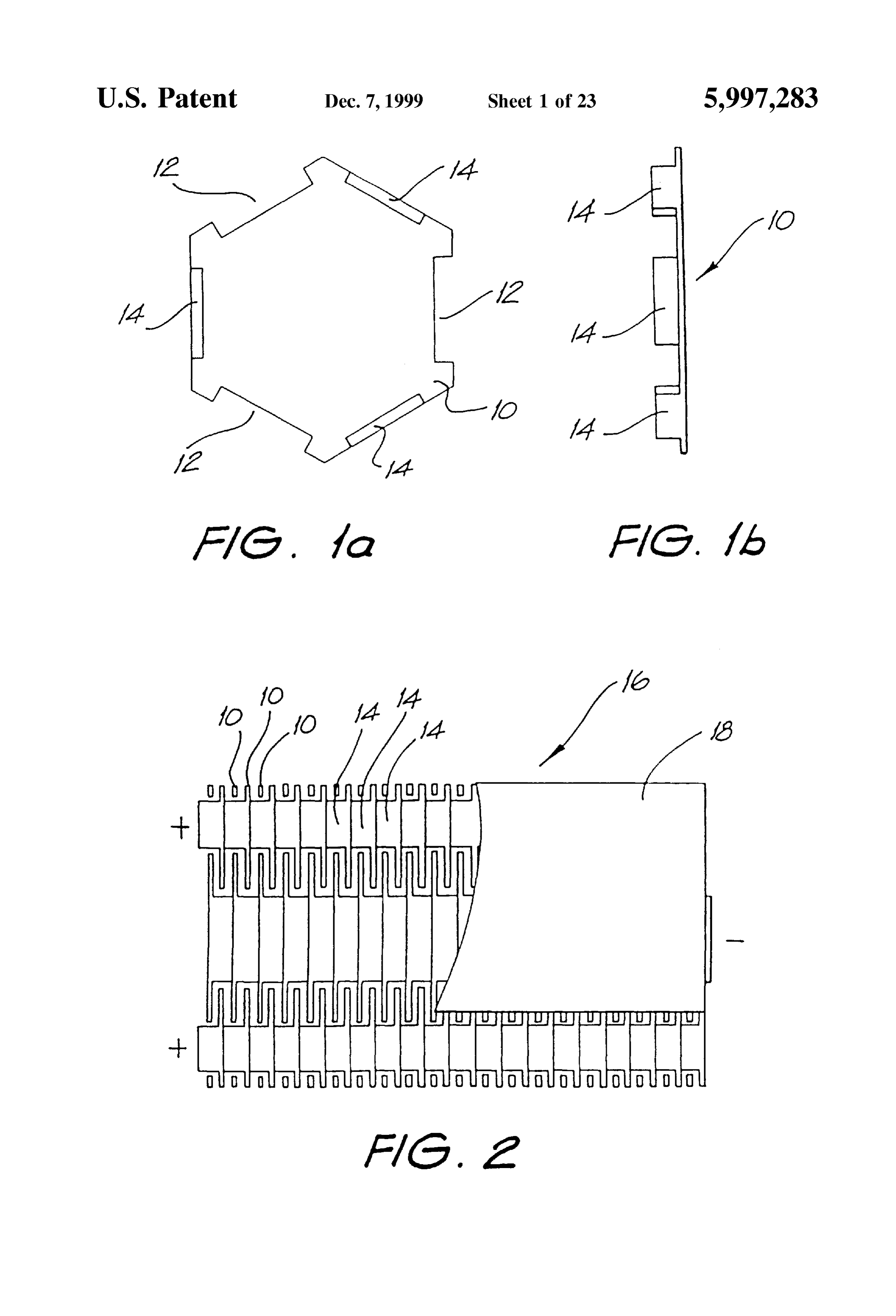
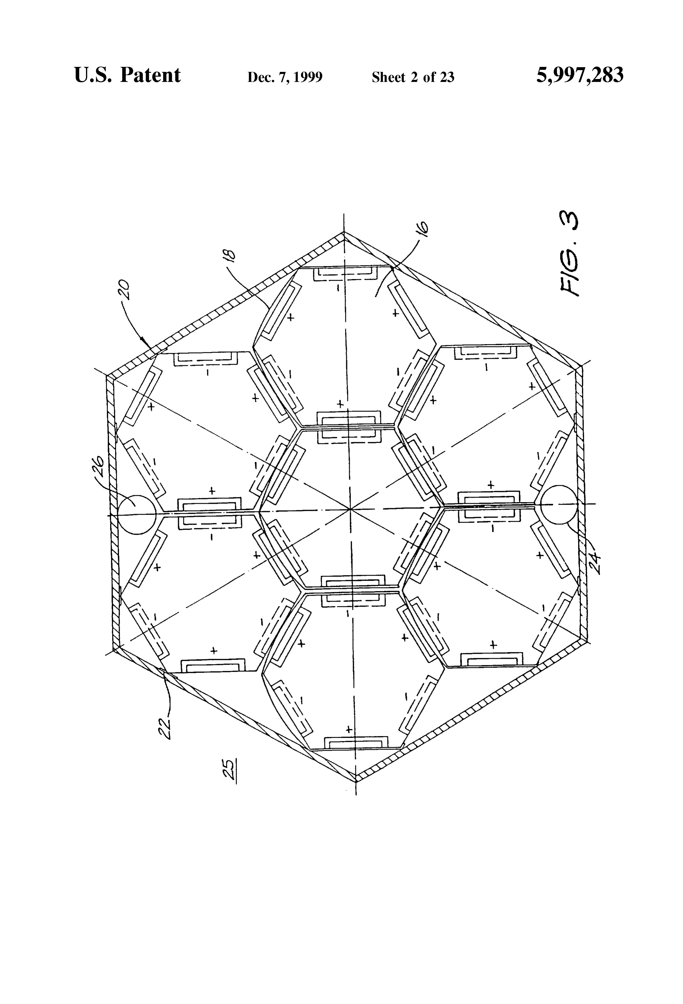
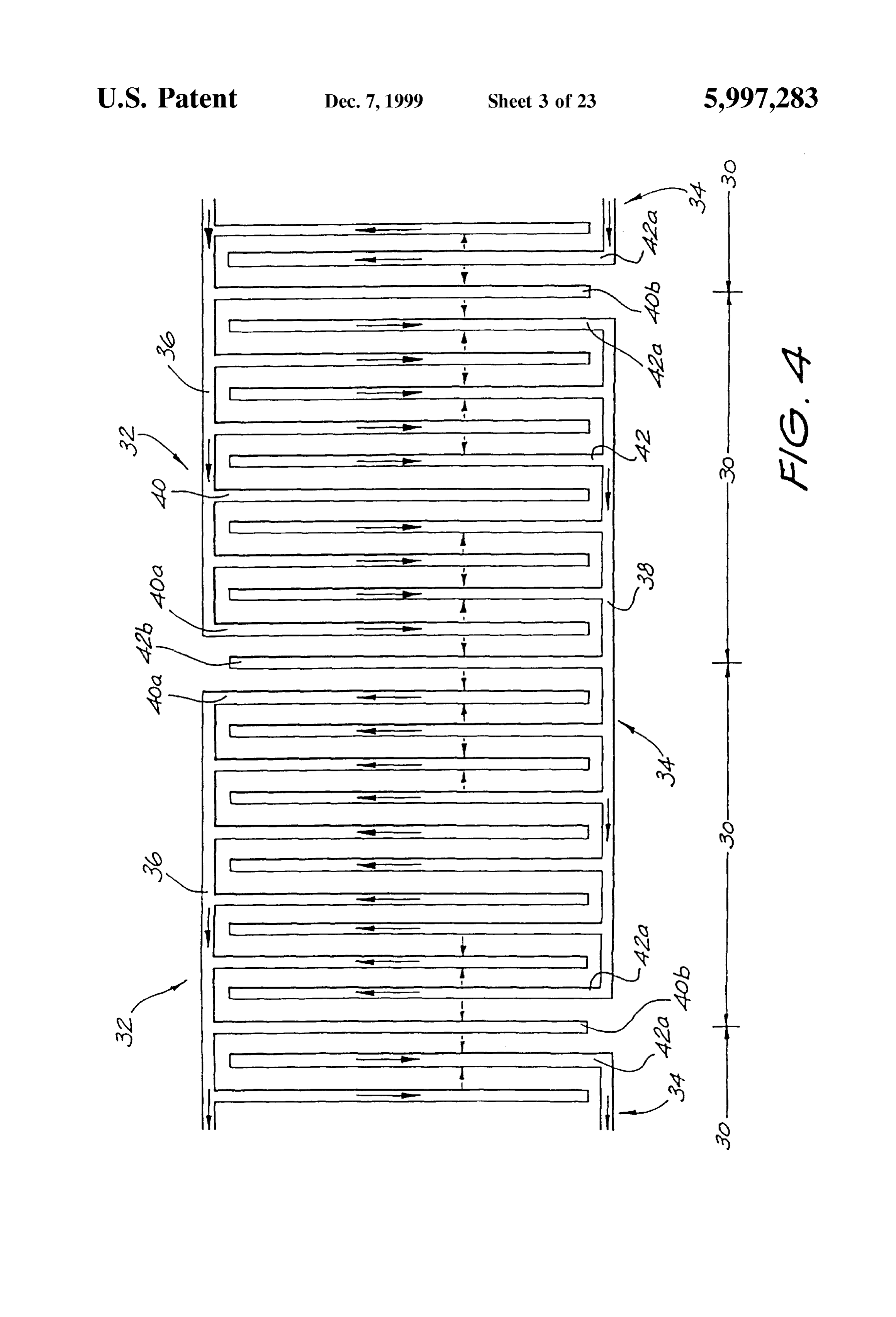
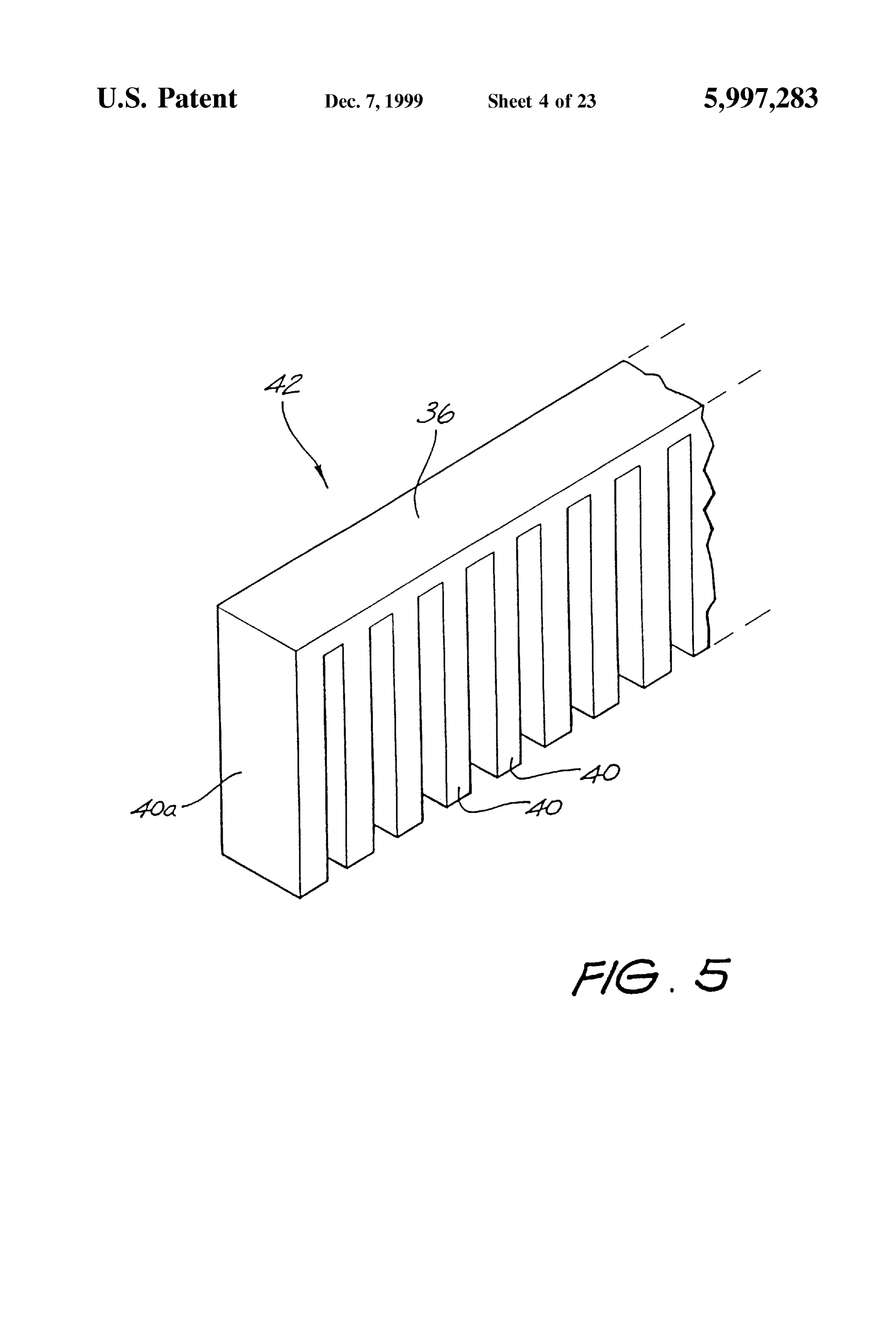
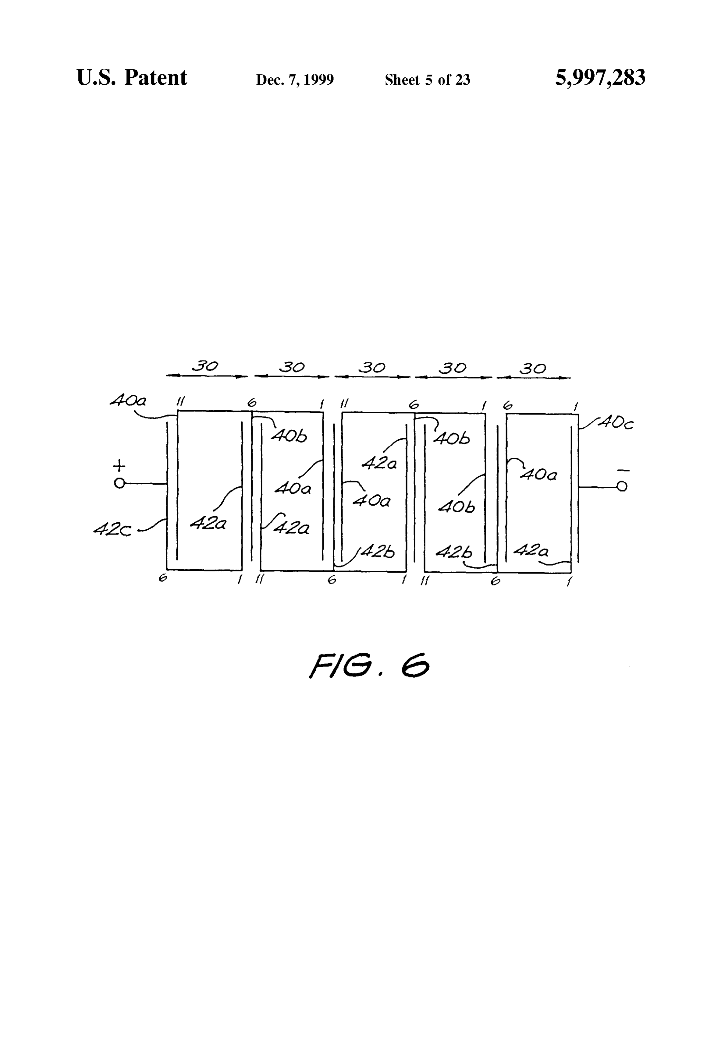
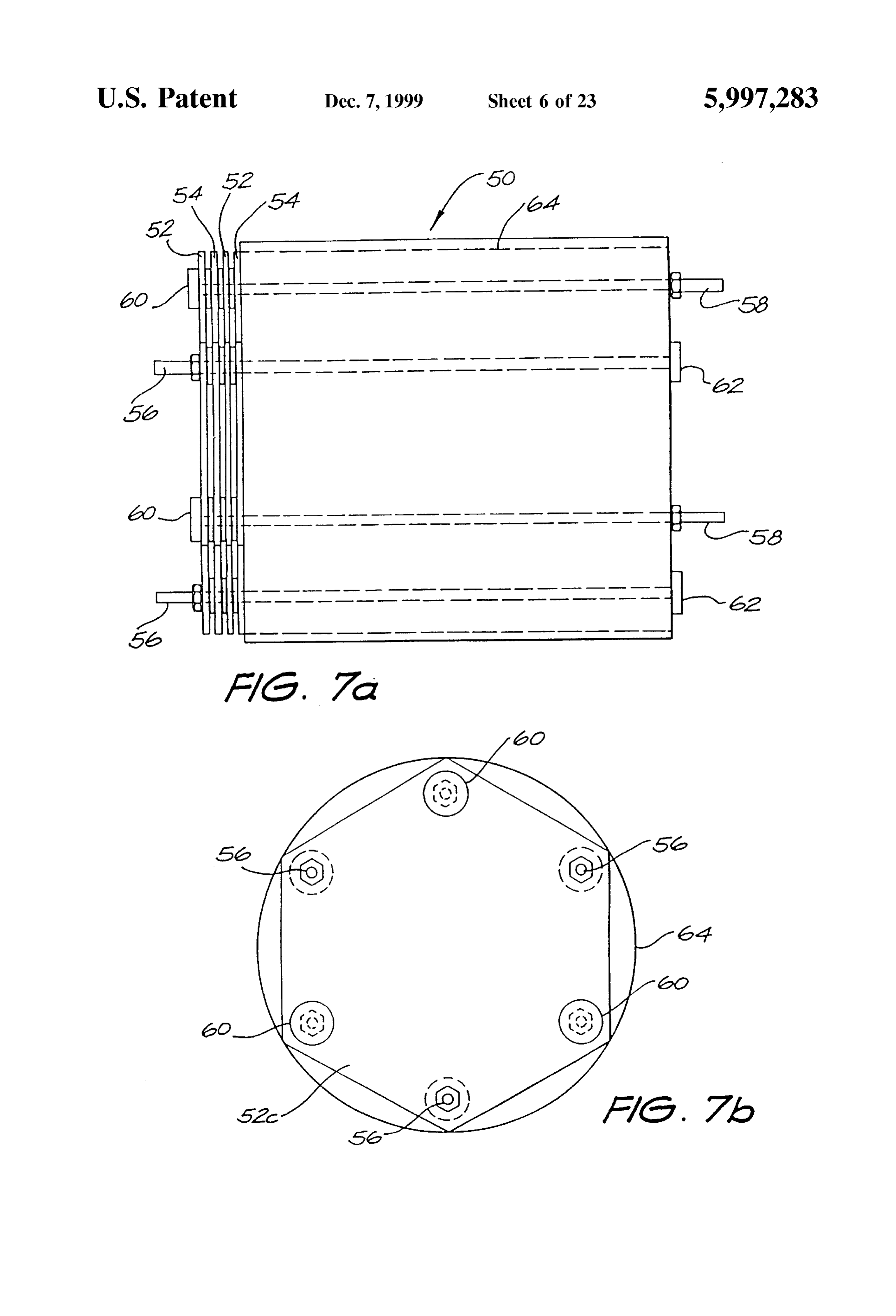
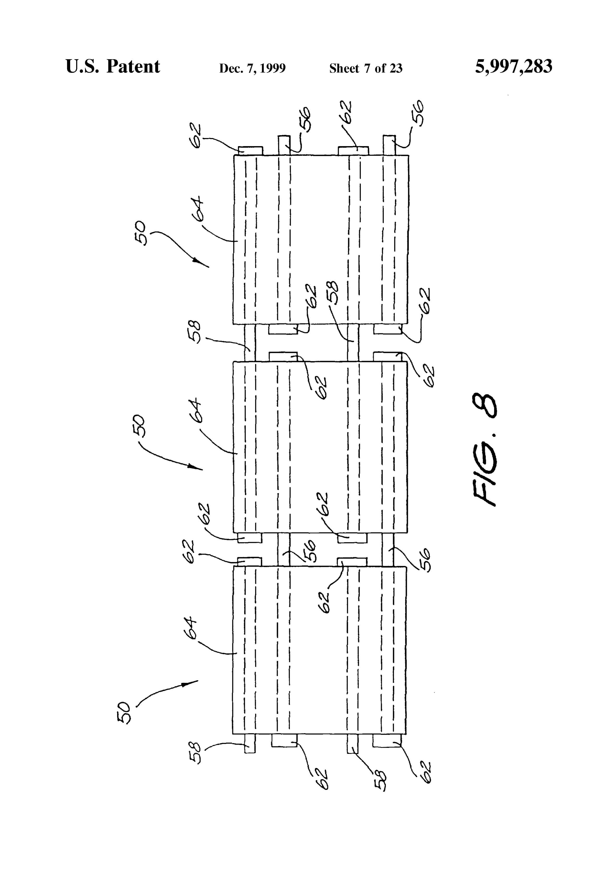
FIGS. 1a and 1b show a single cell plate respectively as contacting that plate, and So contact the next Subsequent a plan View and Side view; plate forming a conductive path between each alternate FIG. 2 shows a Stacked array of cell plates, plate. In this way, the completed cell Structure 16 has three FIG. 3 shows, as a vertical cross-sectional view, an positive end terminals and three negative end terminals, electrolysis cell bank; although FIG. 2 shows only two of the positive terminals FIG. 4 is a vertical cross-sectional view showing an and one of the negative terminals. The cell Stack 16 is arrangement of electrodes of part of another electrolysis cell enveloped by an insulating case 18 (shown in cut-away bank embodying the invention; form). The cell plates 10 shown in FIGS. 1a, 1b and 2 are FIG. 5 is a perspective view of part of one electrode 25 Suited to being in a parallel electrical arrangement, with each shown in FIG. 4; adjacent two cell plates 10 forming either the anode or the FIG. 6 is a simplified representation of a Series arrange cathode.
ment of the electrodes shown in FIG. 4; Parallel stacked flat cell plates are described in Australian FIGS. 7a and 7b show the mechanical arrangement of a Patent No. 487062. There, a stacking of twenty cell plates Single cell Stack in another embodiment; typically requires a potential difference acroSS the individual FIG. 8 shows the arrangement of a number of the cells electrodes of each cell plate in the range of 1.55-2.0 volts to shown in FIGS. 7a and 7b, liberate hydrogen and oxygen gas from the water containing FIG. 9 shows the Series electrical configuration of a an electrolyte of typically 15% sodium hydroxide solution. number of cells in a cell bank; FIG. 3 shows, as a vertical croSS-Sectional view, Seven FIGS. 10a and 10b show the mechanical configuration of 35 complete cell Stacks 16 arranged in a hexagonal matrix and a cell bank assembly; enclosed by a Steel casing 20, thereby to provide an elec FIGS. 11a and 11b show a yet further embodiment of a trolysis cell bank 25. The cell stacks 16 are insulated from cell plate; the steel casing 20 by nylon insulating bushes 22. The FIGS. 12a and 12b show a complementary cell plate to electrical interconnection of the individual cell stacks 16 is that of FIGS. 11a and 11b, 40 not shown, but typically the cells are connected between
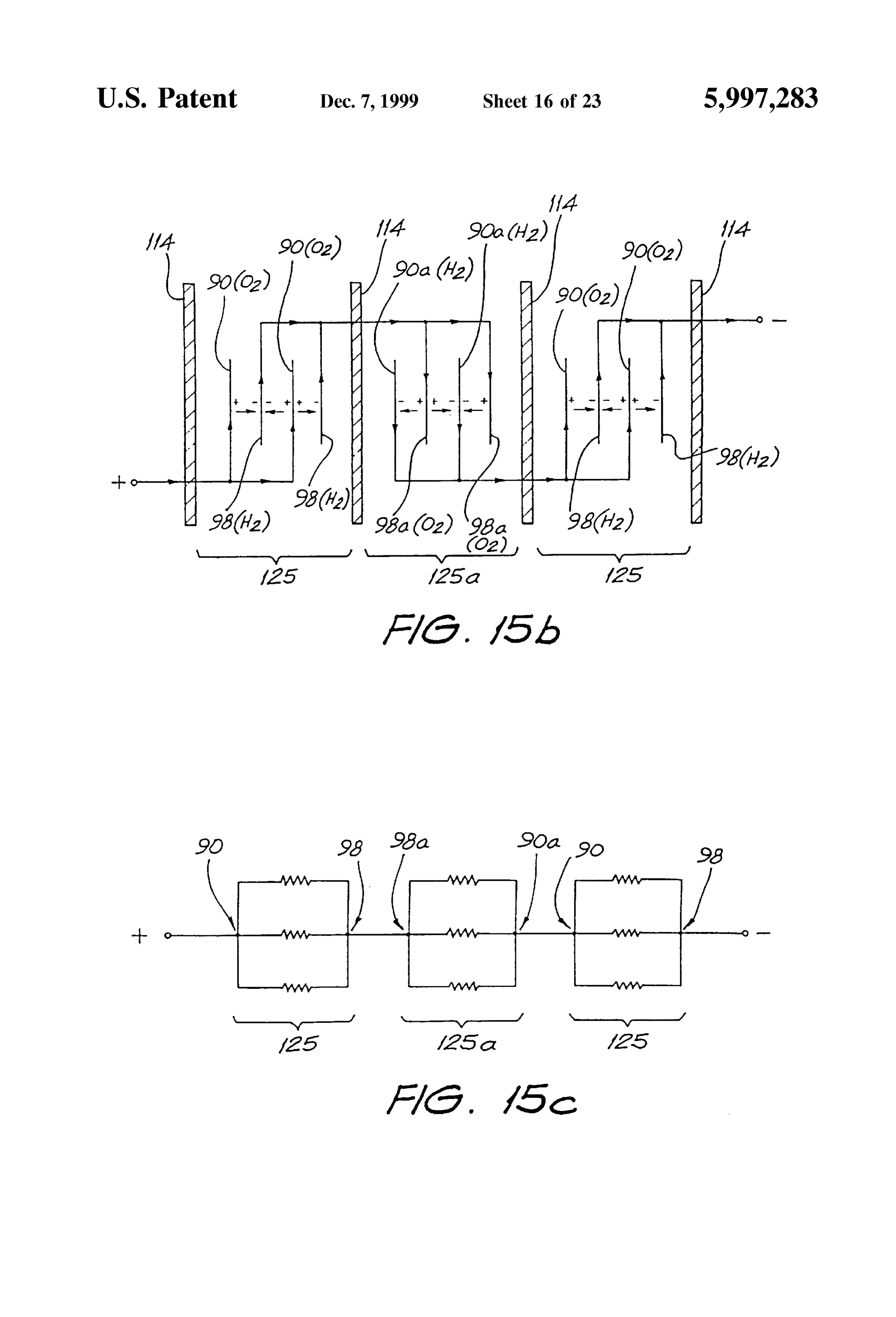
FIG. 13 shows detail of the perforations and porting of the their respective positive (+) and negative (-) terminals by cell plates of FIGS. 11a, 11b, 12a and 12b; Straps to form a Series connection. FIG. 14 shows an exploded stacked arrangement of the It Sometimes can be the case that a parallel interconnec cell plates of FIGS. 11a, 11b, 12a and 12b; 45 tion of the cell stacks 16 is implemented. The actual elec FIG. 15a shows a schematic view of the gas separation trical interconnection will depend upon the number of system of FIG. 14; individual cell plates 10 comprising each cell Stack 16, the FIG. 15b shows a stylised representation of FIG. 15a, Supply Voltage and the current that can be drawn from the FIG. 15c shows an electrical equivalent circuit of FIG. Supply.
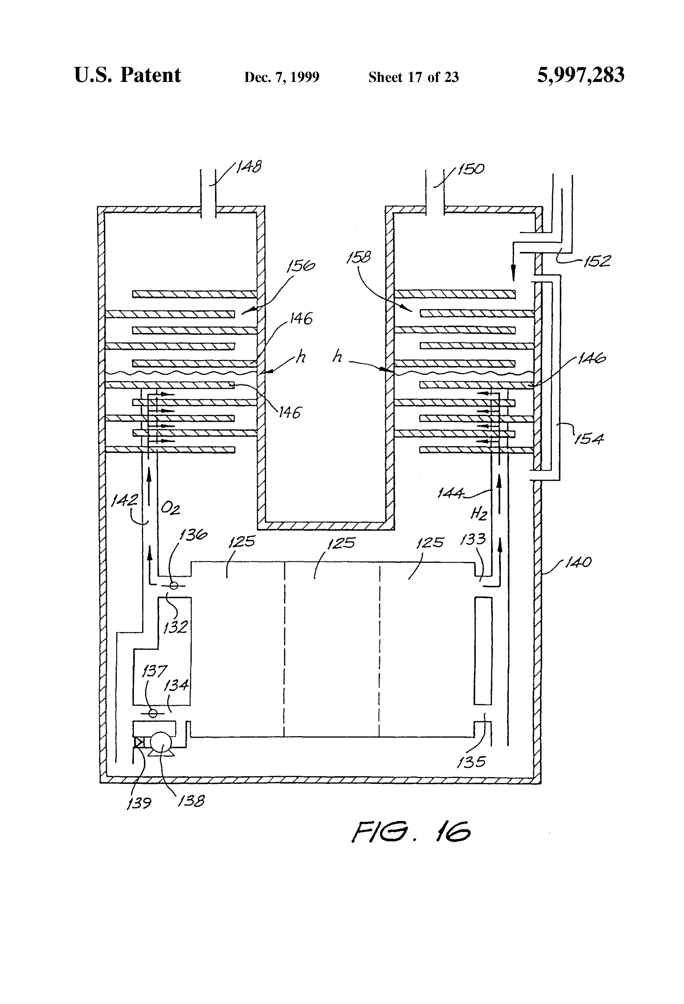
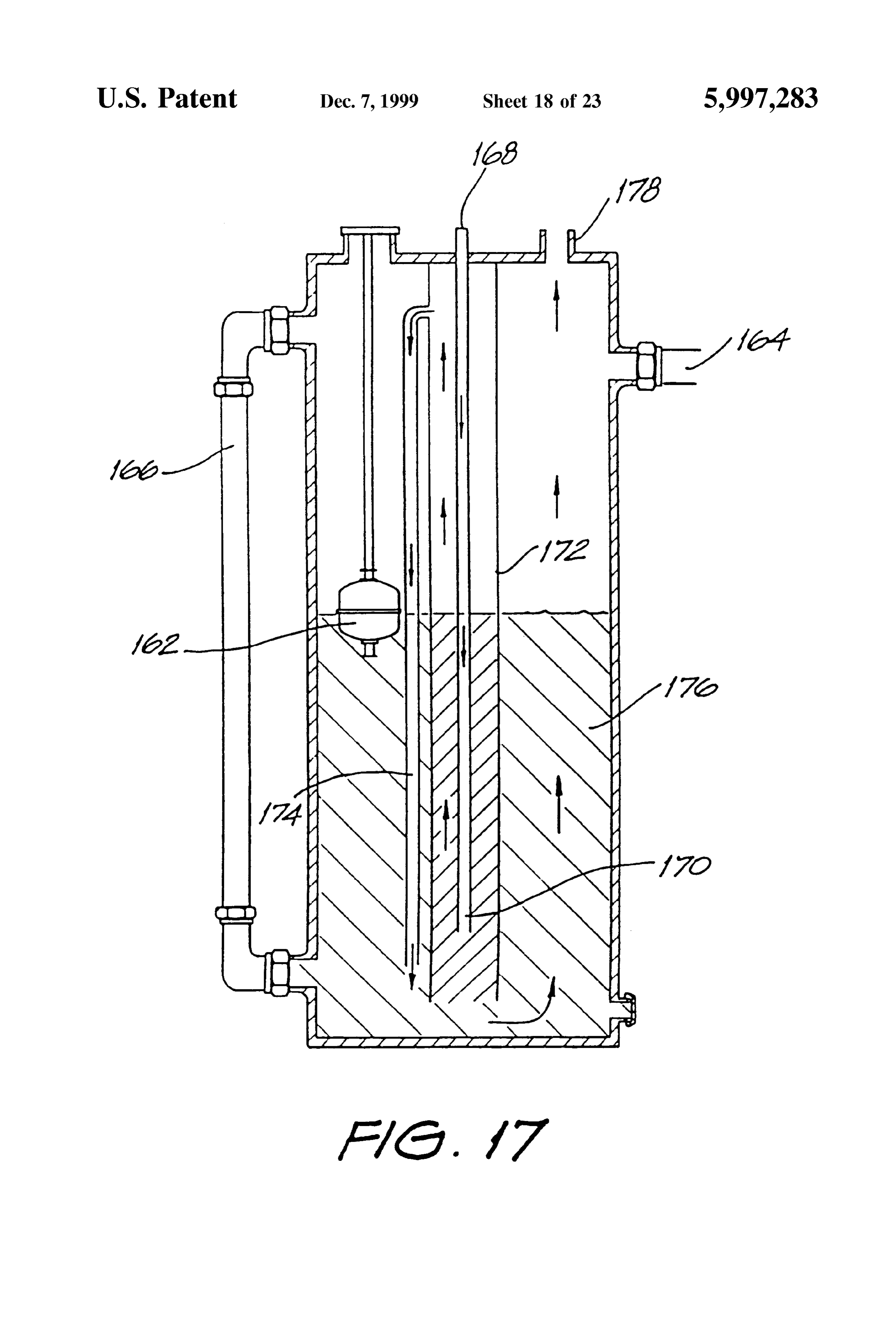
15a, 50 Water is consumed as the hydrogen and oxygen gas is FIG.16 shows a gas collection system for use with the cell liberated during the electrolysis reaction. One liter of water bank separation system of FIGS. 14 and 15a, generates 1860 liters of admixed oxygen and hydrogen at FIG. 17 shows, as a cross-sectional view, a hydraulic STP, in the volumetric proportion noted above. In the Scrubber and check valve; arrangement shown water is continually Supplied through FIG. 18 shows, as a cross-sectional view, a welding tip of 55 the inlet port 24.
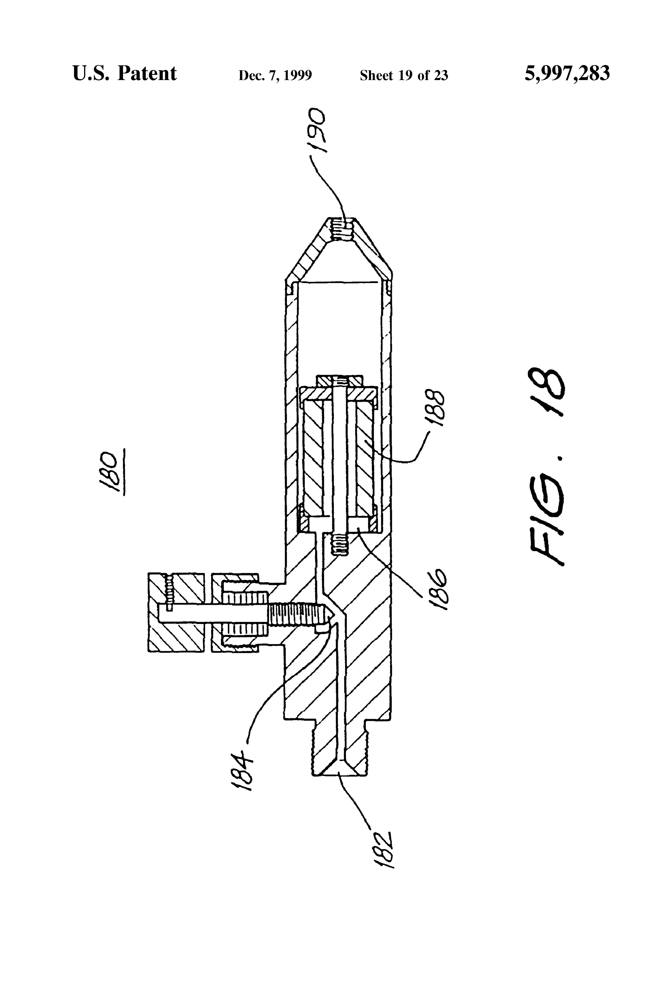
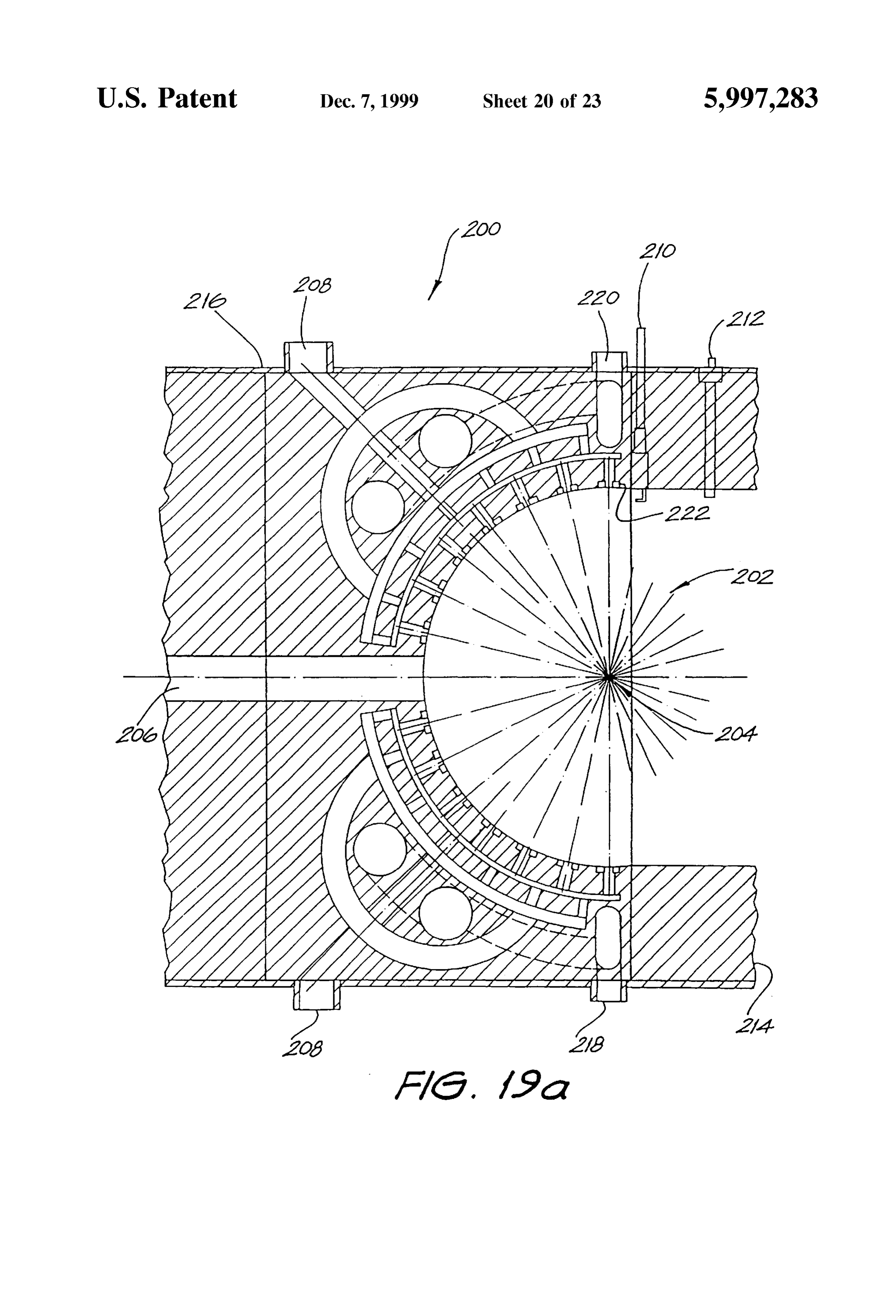
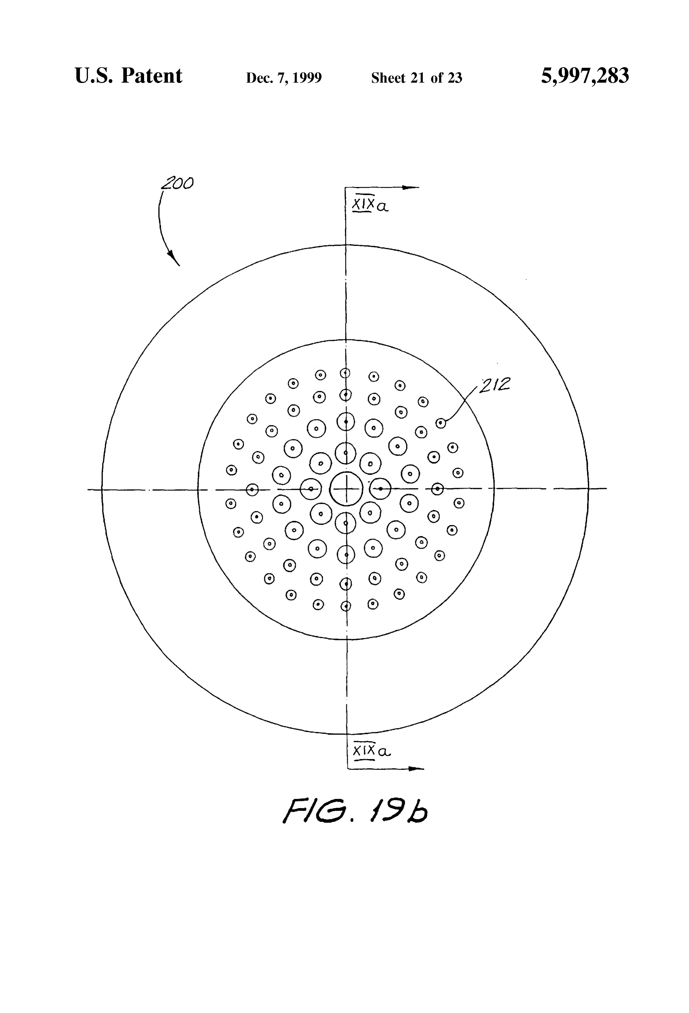
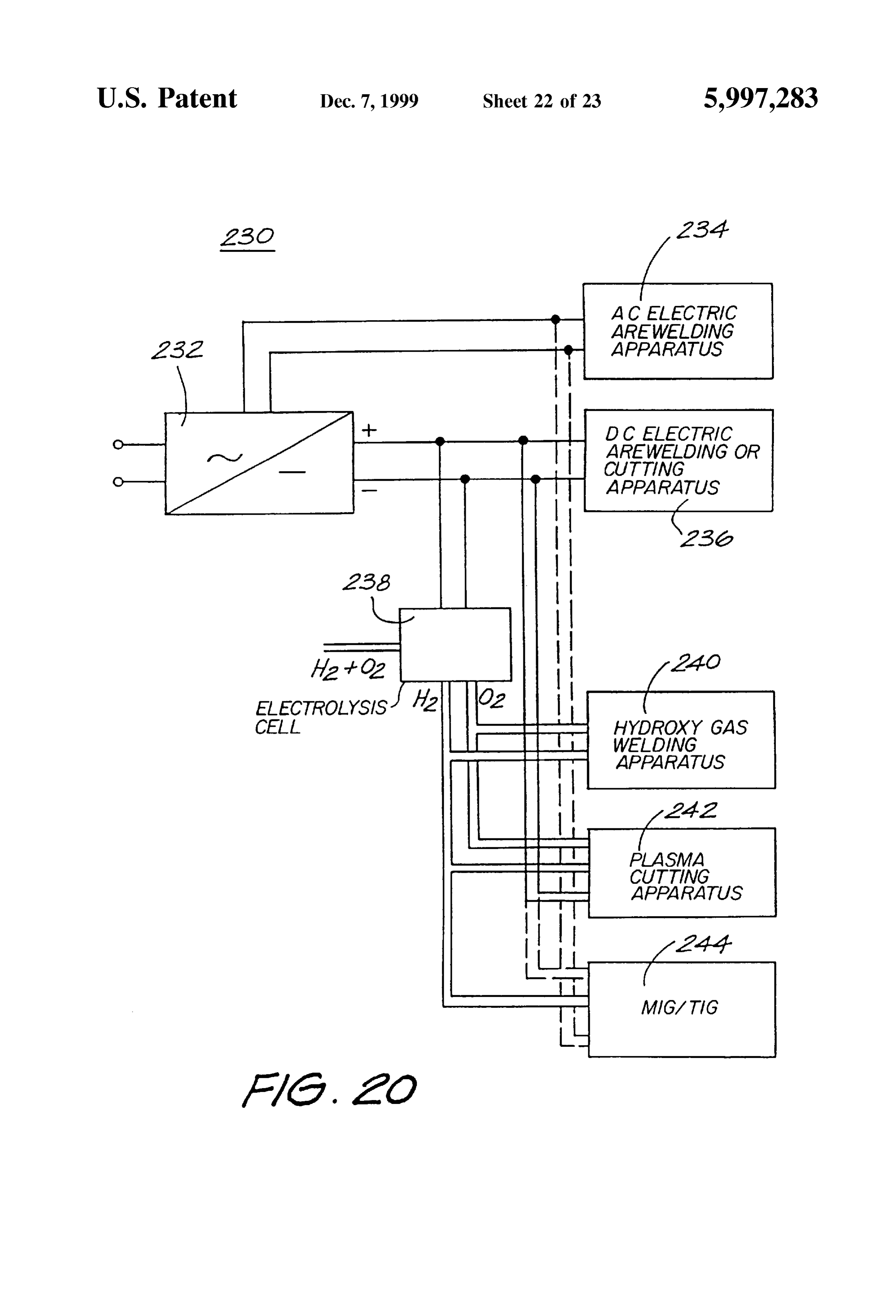
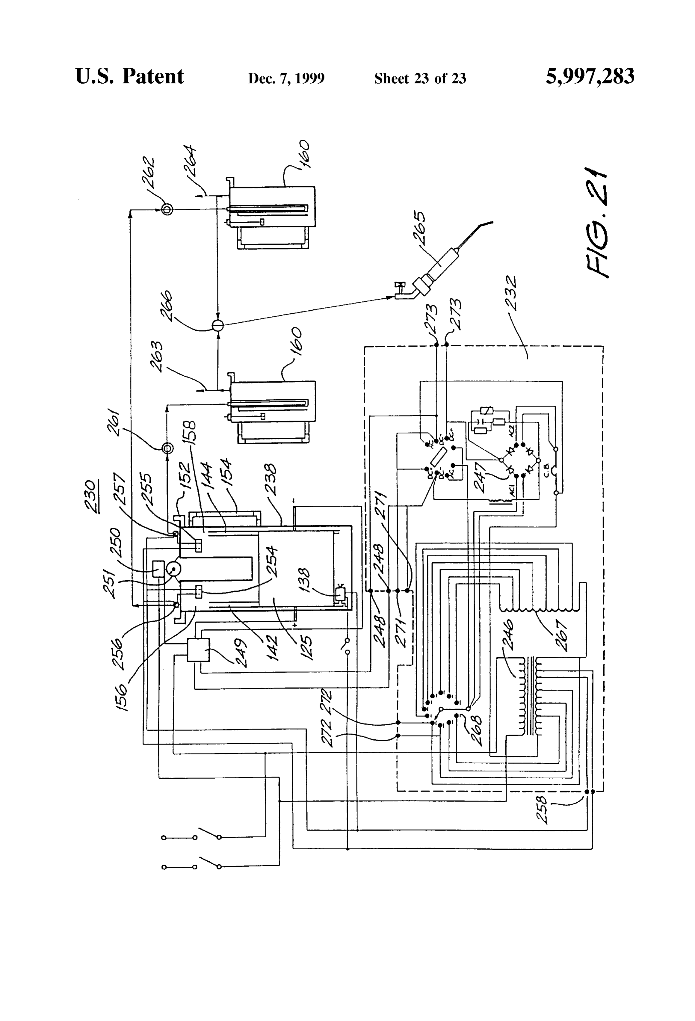
FIG. 10 including a flashback arrester; The nylon covers 18 Separating adjacent Stacks have the FIGS. 19a and 19b show a burner for the destructive benefit of directing the liberated gas upwardly to be col combustion of pollutants, lected by Such as a gas outlet 26 located at the top of the FIG. 20 shows a a block diagram of a multi modal electrolysis cell bank 25. By virtue of volumetric displace welding and cutting apparatus, and 60 ment in a ratio of 1:1860, the liberated gases are self FIG. 21 shows a Schematic diagram of the apparatus of preSSurising as they pass from the outlet port 26 into the FIG. 20. interconnecting pipe work (not shown), which has a far narrower croSS-Sectional area than that of the cell bank.
DETAILED DESCRIPTION AND BEST MODE FIG. 4 is a vertical cross-sectional view showing the OF PERFORMANCE 65 mechanical configuration of an electrolysis cell in accor An electrolysis cell bank embodying the invention is dance with a further embodiment. The basic cell unit 30 is constructed of a number of hexagonally shaped electrolysis constituted by respective halves of a pair of interdigitated
Page 28
electrodes 32.34 arranged much in the nature of interleaved cent ones thereof. The ionic flow naturally will take the path combs. Each electrode is formed by a conductive Spine of least resistance, hence short-circuits between cell units 36.38, typically constructed of resin bonded carbon material, 30, being a path otherwise of greater resistance, are avoided. mild Steel or conductive polymers, from which extend A large number of cells therefore can be arranged to extend eleven finger-like plates 40,42, also constructed of carbon, longitudinally, and allow direct connection to a rectified Steel or conductive polymer. mains power Supply, thus obviating need to electrically FIG. 5 is a perspective view of one of the electrodes 32 interconnect groups of cell units by Strapping, as has been in which the Spine 36 and plates 40 are rectangular in Shape. done in the prior art.
Each individual cell unit 30 satisfies the operational
The electrodes need not necessarily be of the Shape shown, criteria rather can take on many other forms, one example of which So on, toregarding Voltage, the Surface area of the plates and Successfully electrolyse water, and thereby operates will presently be described. The common requirement for all essentially independently of the adjacent cell units 30. Such configurations is that the plates be parallel and inter Testing has established that for a temperature range of 90 connected by a common member usually arranged orthogo C. to 50 C., a DC voltage in the range 1.47-1.56 V applied nally to the plates.
15 across one cell unit 30 (i.e. across one half of a complete
Each pair of electrodes 32.34 are in a Staggered arrange electrode 32 or 34) a minimum (and the optimum) anode ment So that the respective outermost plates 40a,42a are current density of 0.034 A/cm is required to generate a gas offset by approximately one half of the total length of each flow rate of about 340-300 l/h per kWh respectively. The electrode 32,34. The respective mid-point plates are identi discovery that the minimum plate Surface area corresponds fied by the reference numerals 40b and 42b. to the optimum gas flow rate means that the total volume FIG. 6 shows the Staggering arrangement in a simplified occupied can be kept to a minimum. By way of Specific form. Every sixth plate is located in the Space formed example, a rectified 240 V mains Voltage nominally between the first and eleventh plate of the respective results in an average DC voltage of 215 V, hence for direct opposed adjacent electrodes. connection to the mains via a rectifier (i.e. without requiring Referring to FIG. 4 again, two complete cell units 30 and 25 fortya step-down transformer), a total of about one hundred and cells are required. It is particularly advantageous not to a part of the next respective adjacent cell units are shown. require Voltage transforming equipment in terms of equip The total number of cell units is governed by the DC Supply ment cost, technical Simplicity and the avoidance of losses. Voltage, Since a minimum anode/cathode Voltage is required FIG. 7a shows a partial cut-away side view of a cell unit to derive the electrolysis process, and each adjacent cell unit 50 in accordance with another embodiment. The cell unit 50 is in a Series electrical connection of the parallel-arranged is similar in configuration to that of FIG. 4 except for the plates 40.42. In the electrolysis process the cells 30 are number and shape of interconnecting Spine members and the immersed in water and electrolyte and a DC voltage is shape of the electrode plates.
applied between the end-most plates 40c, 42c causing FIG. 7b shows an end view of the cell unit 50, and in elemental ionic currents (some of which are represented by particular the end-most plate 52c. The plate electrodes 52.54 the dashed arrows) to flow between the adjacent plates 35 are hexagonal in shape. Each plate 52,54 has six intercon 40,42, and Sum current-wise along the respective Spines necting rod-like Spines 56.58 passing therethrough, one near 36.38 and plates 40,42 (shown by the solid arrows). A each vertice. Each alternate one of the Spines 56 represents different current path is followed at each mid-plate. For a common positive conductor and the other Set of alternate example, the DC current travels from one end cell plate 42a, Spines 58 represents negative conductors. Each adjacent through the electrolyte, passing through the mid cell plate 40 plate 52,54 is electrically connected either to the positive 40b and again through the electrolyte to the next end cell conductors or the negative conductors. Spacing bushes 60 plate 42a. This process causes the accumulation of net are provided between adjacent plates 52,54 to provide positive charge on one side of the mid-plate 40b, and a electrical isolation and to provide a Space in which the water negative charge on the other side. and electrolyte circulates. Connection of each spine conduc The ionic current flow is accompanied by disasSociation 45 tor 56.58 to the respective plate electrode 52,54 typically is of the water molecules Such that oxygen and hydrogen gas by a threaded nut or interference fit. The reason for con is produced respectively at the anode plate and cathode plate necting each plate 52,54 to three common Spine conductors Surfaces. The cathode plate Surfaces are those Surfaces 56.58 is to achieve a uniform current distribution across the towards which ionic current flows. The converse applies for whole surface area of a plate 52,54.
the anode plate Surfaces. 50 As can be seen in FIG. 7b, the positive spine conductors The Voltage applied across the end-most plates 40c is 56 extend away from one end of the assembly for series divided equally between the constituent cell units 30, with interconnection with other arrangements of cells, as do three that fraction of the Supplied Voltage appearing between the negative spine conductors 58 from the other end. All uncon respective outer-most plates and mid-point plates 4.0a & nected ends of the conductors are blanked-off with a non 42b, 40b & 42a. 55 conductive end cap 62.
The achievable current density is limited, in part, by the FIG. 8 shows a stylised form of three cell units 50 effective electrical resistance of the electrolytic solution. The electrically connected in Series (arranged longitudinally), Smaller the gap between adjacent plates 40,42 the leSS is the and particularly the passage of the Spine conductorS 56,58. resistance. The interdigitated nature of the electrodes 32.34 The cell units 50 are enclosed within an insulating tube 64, means that there is a large Surface area available per unit 60 typically made of PVC, which has access for communica Volume, and there is a minimum Separation between elec tion of water to envelope the plates 52.54 and for the trode plates in all instances. In that case, the resistance of the generated gases to escape.
electrolyte is kept low, hence efficiency of the conversion of FIG. 9 shows the series electrical interconnection of a electrical energy to generate the hydrogen and oxygen gases number of cell units 50 directly connected with the DC is greater than in the prior art. 65 output side of an AC/DC converter 66 (such as a simple By virtue of the Specific arrangement shown, it is not diode bridge rectifier) without requiring a step-down trans necessary to isolate each individual cell unit 30 from adja former.
Page 29
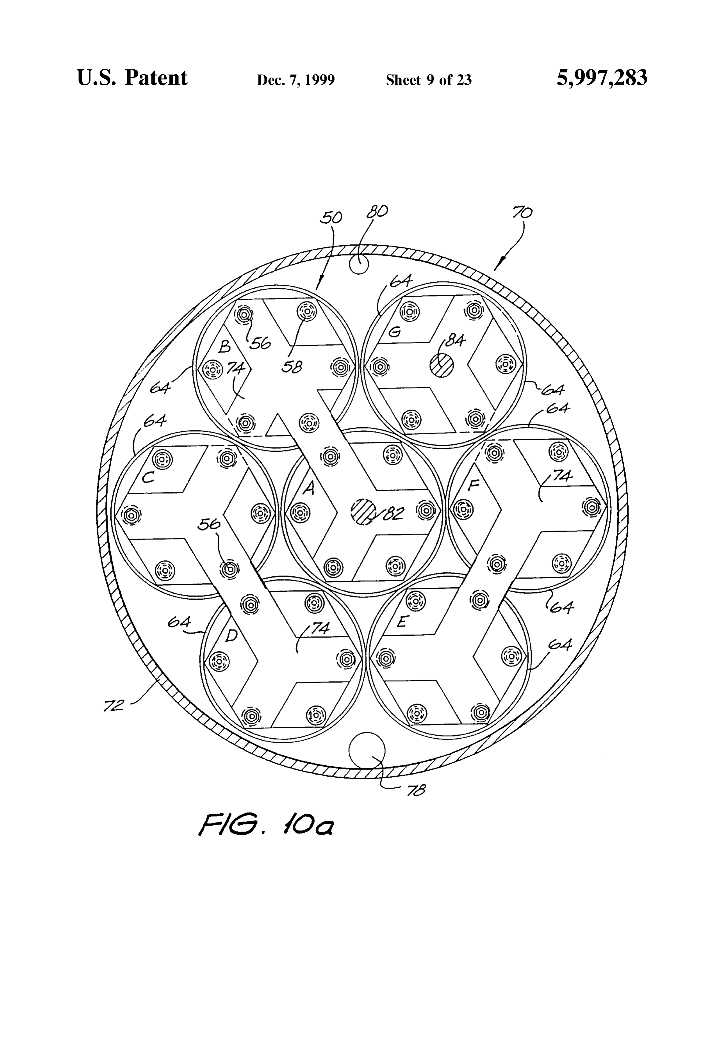
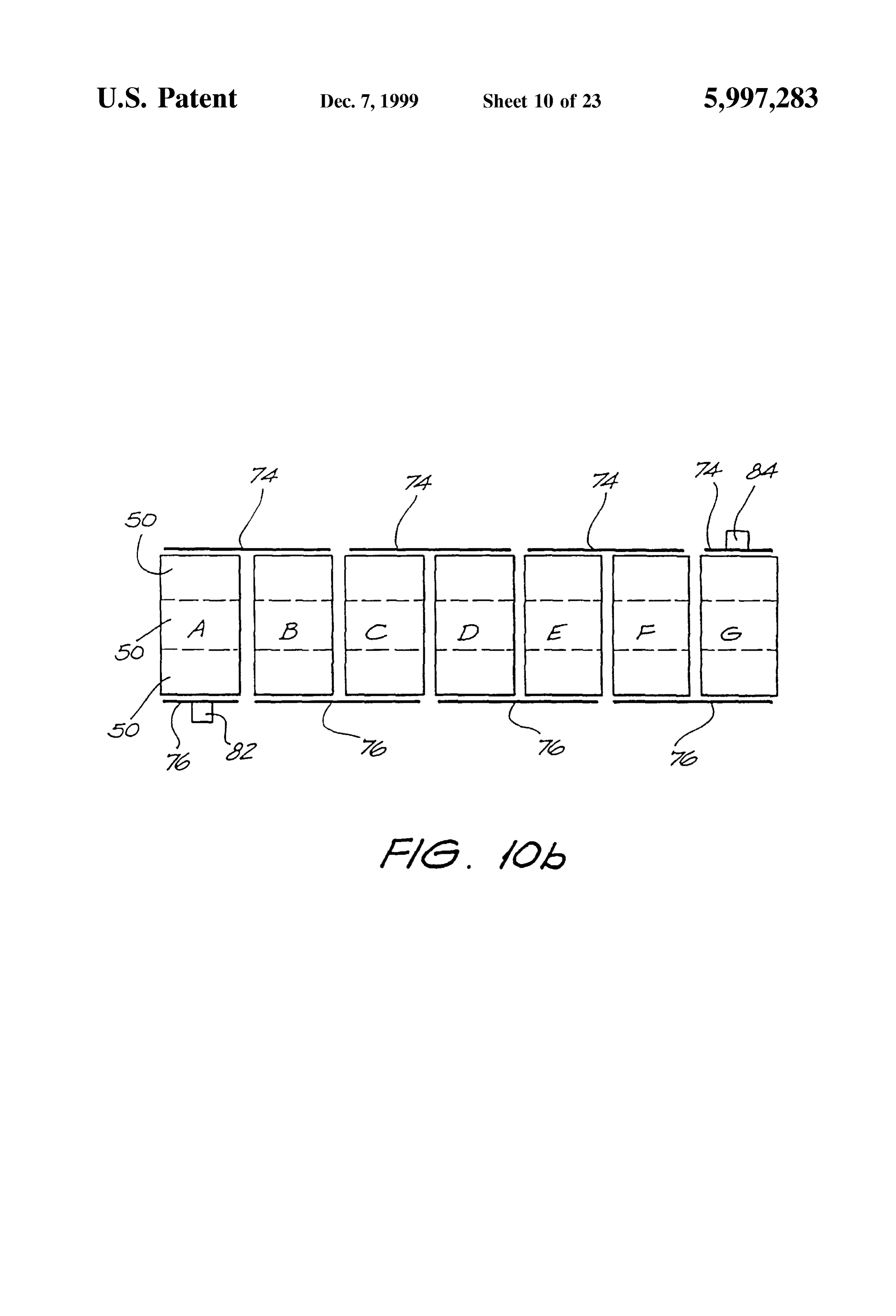
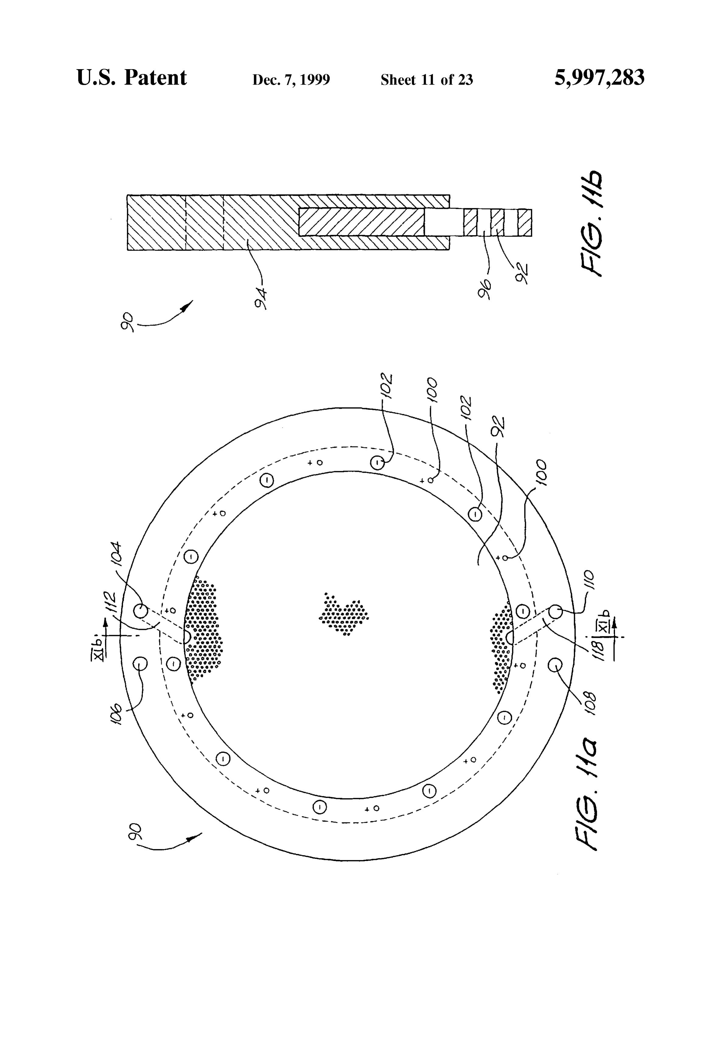
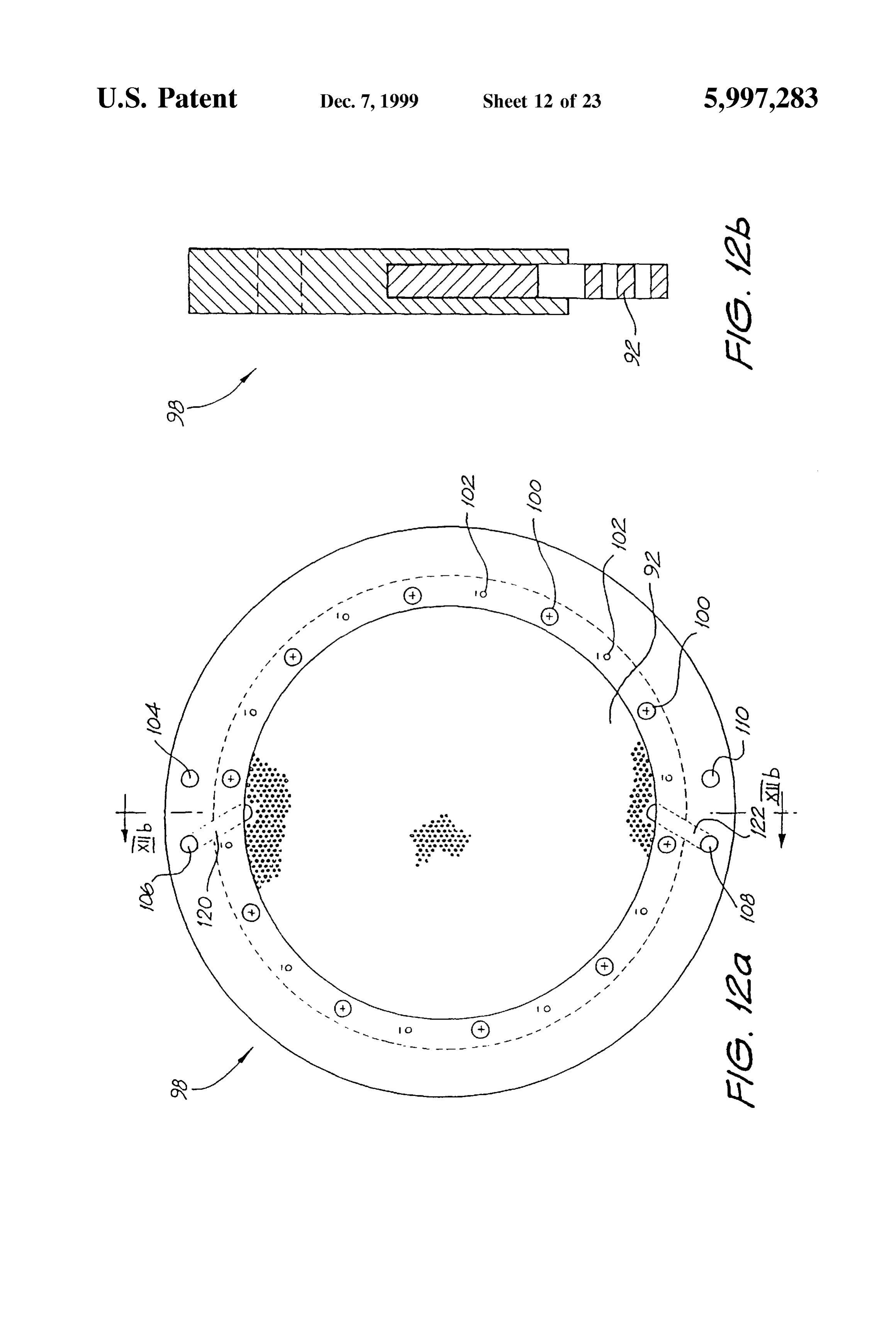
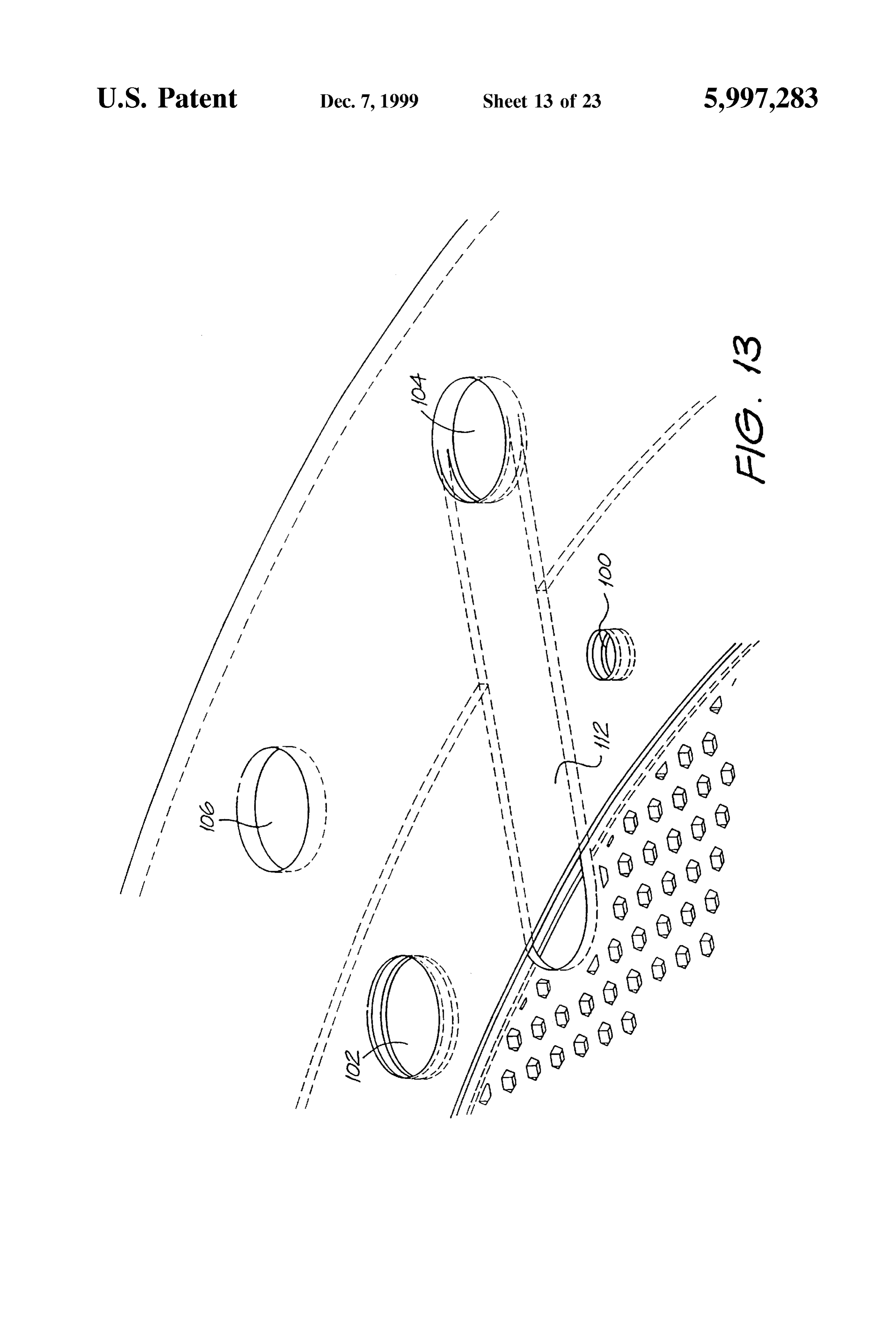
FIG. 10a shows an end view of the mechanical arrange and hydrogen gases respectively. The further holes 108,110 ment of Seven assemblies (designated A-G), each consisting at the bottom of the sleeve 94 are provided for the inlet of of three series connected cell units 50 (as shown in FIG. 8), water and electrolyte to the respective cell plates 90.98. forming a total cell arrangement 70. The cell assemblies 50 FIG. 13 shows an enlarged view of a portion of the cell are located within a Steel cylinder 72 containing the water plate 90 shown in FIG. 11a. The port hole 104 is connected and electrolyte required for the generation of the hydrogen to the hexagonal perforations 96 within the sleeve 94 by an and oxygen gases. Each group (A-G) of three cell units 50 internal channel 112. A similar arrangement is in place for is interconnected by means of a first group of Steel connect the other port hole 106, and for the water/electrolyte supply ing Straps 74 at one end and a Second group of Steel holes 108,110.
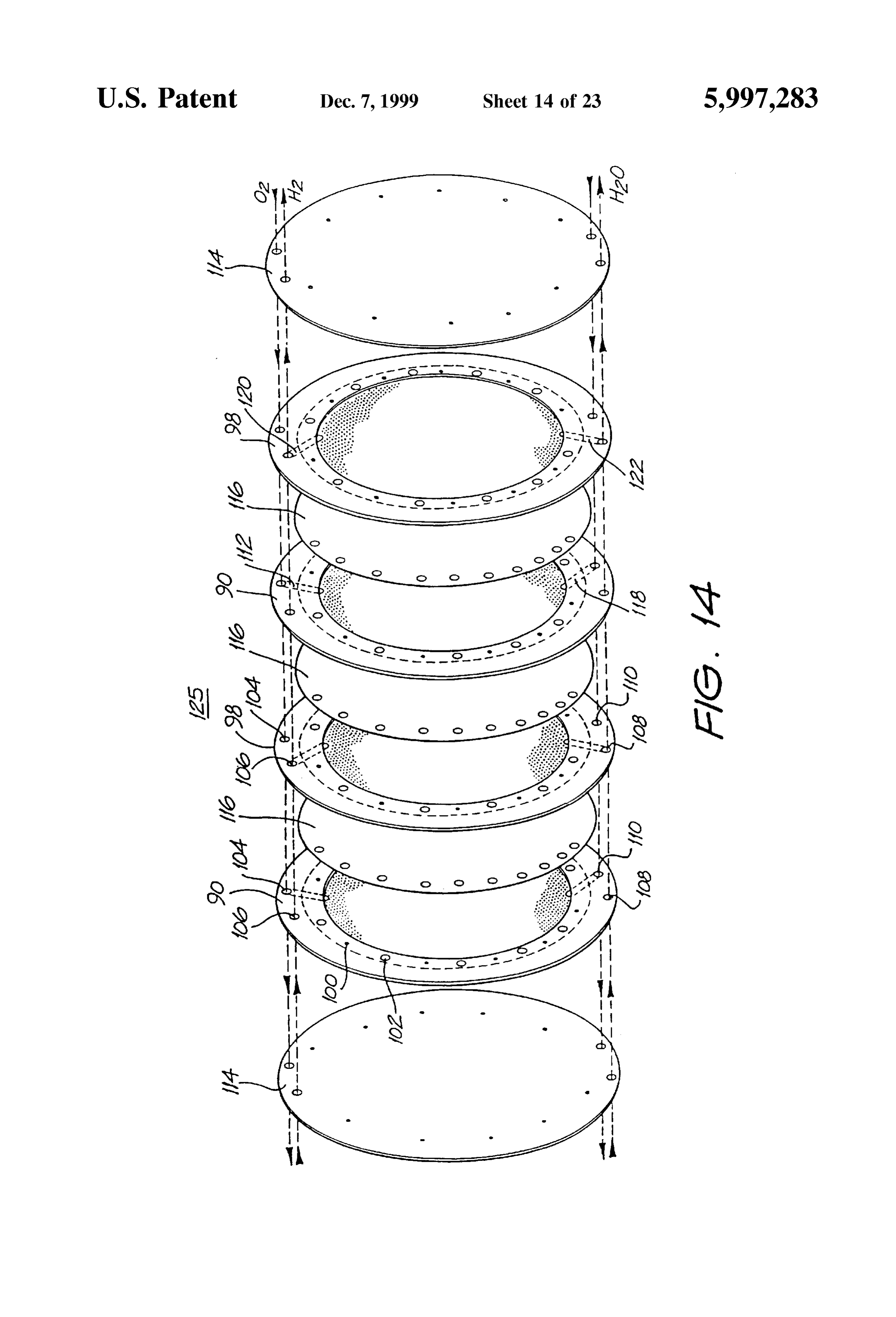
connecting straps 76 (not shown) at the other end, arranged If it is the case that the hydrogen and oxygen gases to be offset between the groups. Whilst the first straps 74 liberated are to be kept separate (i.e. not to be formed as an alone are shown in FIG.10a, both sets of the straps 74.76 are admixture), then it is necessary to separate those gases as more clearly shown in FIG. 10b, which is a side view of the they are produced. In the prior art this is achieved by use of groups A-G when unravelled. diaphragms that block the passage of gases and effectively The PVC tubes 64 shown in FIG. 10a insulate adjacent 15 isolate the water/electrolyte on each Side of the diaphragm. groups to avoid short-circuiting effects between one Ionic transfer thus is facilitated by the ionically conductive another. The cell arrangement 70 is very compact, and in a nature of the diaphragm material (i.e. a water-diaphragm comparison with the prior art Brown arrangement is only water path). This results in an increase in the ionic resistance one third of the physical size for a comparable gas Volu and hence a reduction in efficiency. Prior art patent No. metric flow rate, there also being a similar reduction in total 487062 describes another arrangement (see FIG. 6 thereof) mass. The Supply of water for the electrolysis proceSS is by that utilises magnets to cause Separation of the gases. an inlet 78 located at the bottom of the cylinder 72, with the FIG. 14 shows an exploded stacked arrangement of four gases produced exiting the cylinder 72 by an outlet 80 cell plates, being an alternative Stacking of two (anode) cell located at the top of the cylinder. plates 90 and two (cathode) cell plates 98. The two ends of Electrical connection to a DC power Supply is acroSS the 25 the Stacked arrangement of cell plates delineates a Single cell totality of the cells, and in the arrangement is at a central unit 125. Interposed between each adjacent cell plate 90.98 terminal 82 on the underside cell A and a central terminal 84 is a PTFE separation 116. Although not shown in FIG. 14, on the top Side of cell G respectively. the cell unit includes Separate hydrogen and oxygen gas FIGS. 11a and 12a show further embodiments of a first conduits that respectively pass through the Stacked arrange and second type of cell plate 90.98 as an end view. FIGS. ment of cell plates via the port holes 106,104 respectively. 11b and 12b are partial cross-sectional views along the In a similar way, conduits are provided for the Supply of respective mid-lines as shown. Common reference numerals water/electrolyte, respectively passing through the holes have been used where appropriate. The plates 90.98 can 108,110 at the bottom of the respective plates 90.98. have the function of either an anode (+) or a cathode (-), as 35 Only two pairs of anode/cathode cell plates are shown. will become apparent. Each comprises an electrode disc 92 The number of Such plates can be greatly increased per cell that is perforated with hexagonally shaped holes 96. The unit 125.
disc 92 is made from steel or resin-bonded carbon or Also not shown are the interconnecting conductive shafts conductive polymer material. The disc 92 is housed in a that electrically interconnect alternative common cell plates. circular rim or sleeve 94. The function of the perforations 96 40 The reason for having a large diameter hole in one cell plate is to maximise the Surface area of the electrode disc 92 and adjacent to a Smaller diameter hole in the next cell plate, is minimise the weight by over solid constructions 45%. So that an interconnecting Shaft will pass through the larger By way of example, for a disc of diameter 280 mm, the diameter hole, and not make an electrical connection (i.e. thickness of the disc must be 1 mm in order to allow the insulated with PVC tubing) rather only forming an electrical current density (which ranges from 90 A/2,650 cm-100 45 connection between alternate (common) cell plates. A/2,940 cm of the anode or cathode) to be optimal. If the The cell unit 125 shown in FIG. 14 arrangement is an diameter of the plate is increased, which consequently exploded view. When fully constructed, all the elements are increases the Surface area, it is necessary to increase the Stacked to be in intimate contact. Mechanical fastening is thickness of the plate in order to maintain uniformity of achieved by use of one of two adhesives Such as (a) conductance for the desired current density. 50 “PUR-FECT LOK” (TM) 34-9002, which is a Urethane The hexagonal perforations in a 1 mm thick disc have a Reactive Hot Melt adhesive with a main ingredient of distance of 2 mm between the flats and are 1 mm away from Methylene Bispheny/Dirsocynate (MDI), and (b) “MY-Tthe next adjacent perforation, in order to maintain the same BOND” (TM) which is a PVC solvent based adhesive. Both total Surface area prior to perforation, and to allow the adhesives are Sodium Hyroxide (20% present in the current density to be optimal. A 1 mm (flat to flat) distance 55 electrolyte) resistant. In that case the water/electrolyte only between the adjacent hexagonal perforations is required resides within the area proscribed by the cell plate sleeve 94. because a Smaller distance will result in thermal (resistive) Thus the only path for the inlet of water/electrolyte is by losses and a larger distance will add to the overall weight of bottom channels 118,122 and the only outlet for the gases is the plate. by the top channels 112,120. In a system constructed and The sleeve 94 is constructed of PVC material and incor 60 tested by the inventor, the thickness of the cell plates 90.98 porates a number of equally spaced shaft holes 100,102. The is 1 mm (2 mm on the rim because of the PVC sleeve 94), holes are for the passage of interconnecting Shafts provided with a diameter of 336 mm. The cell unit 125 is segmented in a stacked arrangement of the plates 90,98 forming the from the next cell by an insulating PVC segmentation disc common conductor for the respective anode and cathode 114. A Segmentation disc 114 also is placed at the beginning plates, much in the nature of the arrangement shown in 65 and end of the entire cell bank.
FIGS. 7a and 7b. The further two upper holes 104,106 each If there is to be no control over separation of the liberated Support a conduit respectively for the out-flow of oxygen gases, then the PTFE membranes 116 are not provided.
Page 30
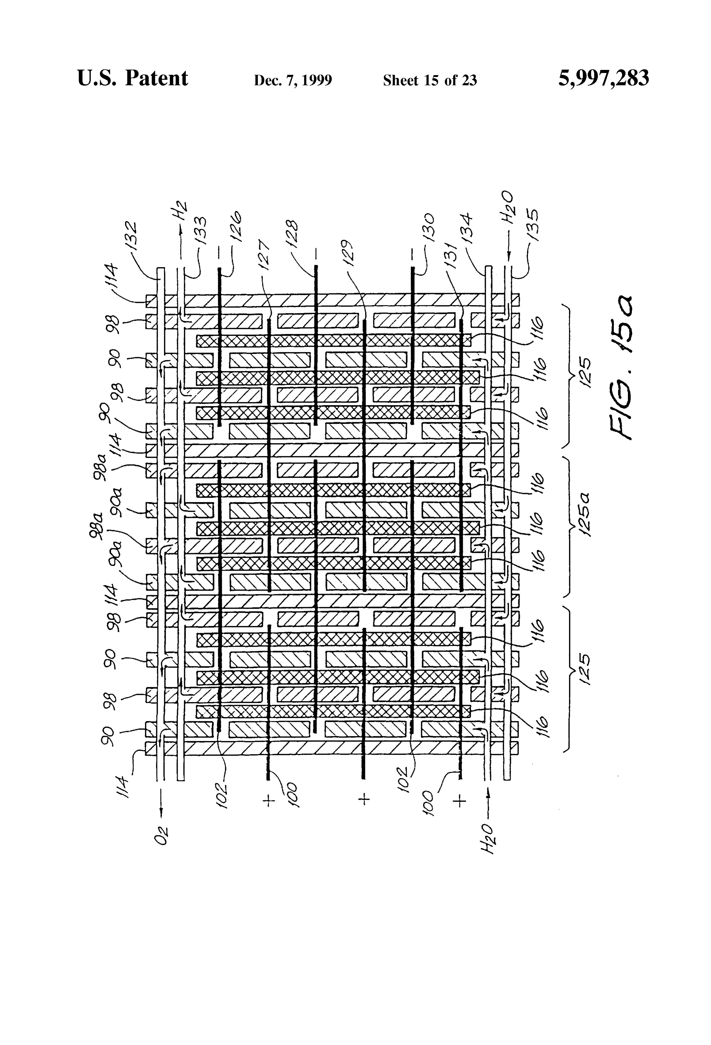
The PTFE membrane 116 is fibrous and has 0.2 to 1.0 The upper extent of the tank 140 forms two scrubbing micron interstices. A Suitable type is type Catalogue Code J, towers 156,158, respectively for the collection of oxygen supplied by Tokyo Roshi International Inc (Advantec). The and hydrogen gases. The gases pass up a respective column water/electrolyte fills the interstices and ionic current flows 142,144, and out from the columns via openings therein at only via the water-there is no contribution of ionic flow a point within the interleaved baffles 146. The point where through the PTFE material itself. This leads to a reduction in the gases exit the columns 142,144 is beneath the water level the resistance to ionic flow. The PTFE material also has a h, which serves to settle any turbulent flow and entrained “bubble point that is a function of pressure, hence by electrolyte. The baffles 146 located above the level h scrub controlling the relative pressures at either side of the PTFE the gas of any entrained electrolyte, and the Scrubbed gas Separation sheets, the gases can be forced through the then exits by respective gas outlet columns 148,150 and so interstices to form an admixture, or otherwise kept Separate. to a gas receiver. The level h within the tank 140 can be Other advantages of this arrangement include a lesser cost of regulated by any convenient means, including a float Switch, construction, improved operational efficiency and greater again with the replenishing water being Supplied by the inlet resistance to faults. pipe 152.
FIG. 15a is a stylised, and exploded, schematic view of a 15 The liberated gases will always separate from the water/ linear array of three series-connected cell units 125. For electrolyte solution by virtue of the difference in densities. clarity, only six interconnecting Shafts 126-131 are shown. Because of the relative height of the respective set of baffles, The shafts 126-131 pass through the respective shaft holes and due to the density differential between the gases and the 102,100 in the various cell plates 90.98 in the stacked water/electrolyte, it is not possible for the liberated hydro arrangement. The polarity attached to each of the exposed gen and oxygen gases to mix. The presence of the full end shafts, to which the DC Supply is connected also is volume of water within the tank 140 maintains the cell plates indicated. The shafts 126-131 do not run the full length of in an immersed State, and further Serves to absorb the shock the three cell banks 125. The representation is similar to the of any internal detonations should they occur. arrangement shown in FIGS. 7a and 8. One third the full DC In the event that a gas admixture is required, then firstly Source Voltage appears acroSS each anode/cathode cell plate 25 the two flow valves 136,137 respectively located in the pair 90,98. oxygen gas outlet conduit 132 and water/electrolyte inlet Further, the gas conduits 132,133, respectively for hydro port 134 are closed. This blocks the outlet path for the gen and oxygen, that pass through the port holes 104,106 in oxygen gas and forces the inlet water/electrolyte to pass to the cell plates 90.98 also are shown. In a similar way, the inlet conduit 134 via a one-way check valve 139 and water/electrolyte conduits 134,135, passing through the pump 138. The water/electrolyte within the tank 140 is water port holes 108,110 in the cell plates also are shown. under pressure by virtue of its depth (volume), and the pump FIG. 15b particularly shows how the relative potential 138 operates to increase the pressure of water/electrolyte difference in the middle cell bank 125 changes. That is, the occurring about the anode cell plates 90.98a to be at an plate electrode 90a now functions as a cathode (i.e. rela increased pressure with respect to the water/electrolyte on tively more negative) to generate hydrogen, and the plate 35 the other side of the membrane 116. This pressure differen electrode 98a now functions as an anode (i.e. relatively more tial is Sufficient to cause the oxygen gas to migrate through positive) to generate oxygen. This is the case for every the membrane, thus admixed oxygen and hydrogen are alternate cell unit. The arrowheads shown in FIG. 15b liberated via the gas output conduit 133 and column 144. indicate the electron and ionic current circuit. FIG. 15c is an Since there is no return path for the water/electrolyte Sup electrical equivalent circuit representation of FIG. 15b, 40 plied by the pump 138, the pressure about the cell plates where the resistive elements represent the ionic resistance 90.98a will increase further, and to a point where the between adjacent anode/cathode plates. Thus it can be seen difference is sufficient such that the water/electrolyte also that the cell units are connected in Series. can pass through the membrane 116. Typically, preSSure Because of the change of function of the cell plates 90a differential in the range of 1.5-10 psi is required to allow and 98a, the complementary gases are liberated at each, 45 passage of gas, and a pressure differential in the range of hence the respective channels 112 are connected to the 10-40 psi for water/electrolyte. opposite gas conduit 132,133. Practically, this can be While only three cell units 125 are shown, clearly any achieved by the simple reversal of the cell plates 90.98. number, connected in Series, can be implemented. FIG. 16 shows the three cell units 125 of FIG. 15a FIG. 17 shows another embodiment of a check valve and connected to a gas collection arrangement. The cell units 50 scrubber unit 160 for scrubbing liberated gas(es) before 125 are located within a tank 140 that is filled with water/ Subsequent use. The unit 160 is filled with water, typically electrolyte to the level h indicated. The water is consumed to a level being about half the full height of the unit. The as the electrolysis proceSS proceeds, and replenishing Supply level is regulated by a float Switch 162. Water is supplied by is provided via the inlet 152. The water/electrolyte level h means of the inlet 164. A sight column 166 is also provided, can be viewed via the Sight glass 154. In normal operation, 55 which Serves to give a visual indication of the water level. the different Streams of hydrogen and oxygen are produced The hydrogen and/or oxygen gases from the gas receiver, and passed from the cell units 125 to respective rising now under pressure, enter by an entry tube 168 having an columns 142,144. That is, the pressure of electrolyte on opening 170 at the bottom end thereof. The gases travel opposed sides of the PTFE membranes 116 is equalised, thus down the tube 168 and out of the opening 170 to bubble the gases cannot admix. 60 upwardly on the inside of the inner column 172, which also The columns 142, 144 also are filled with the water/ is filled with the Supplied water, thus performing a first electrolyte, and as it is consumed at the electrode plates, Scrubbing action to remove the Sodium hydroxide electro replenishing Supply of electrolyte is provided by way of lyte. The gas then enters a further downwardly directed tube circulation through the water/electrolyte conduits 134,135. 174 and out the opened end thereof, passing again through The circulation is caused by entrainment by the liberated 65 the water in the outer chamber 176 to be further scrubbed gases, and by the circulatory inducing nature of the conduits and So to be Stored under pressure within the Space above the and columns. water level, to be available for supply from the outlet 178.
Page 31
Admixed hydrogen and oxygen gases Supplied from the FIGS. 19a and 19b show a configuration for a burner used output 178 to, say, a welding tip (not shown) are in the in the destruction of Such gaseous polluting emissions. FIG. correct Stoichiometric proportions as a result of the elec 19a shows a cross-sectional view of a burner 200. The trolysis process, and ensures that, on combustion, a neutral croSS-Sectional view along the mid-line is shown in FIG. flame is produced. The only products of the combustion 19b. The burner 200 has a combustion chamber 202 that is proceSS are heat and water vapour. hemispherical in Shape. The emissions, which may include If the gases are produced Separately, two check-valve a mixture of fumes containing hydrocarbons and other Scrubbers 160 are employed, the gases can then be mixed in Volatile pollutants as a waste product of industrial processes, a mixing chamber which also will produce the correct are injected to the combustion chamber by an inlet path 206. Stoichiometric mix. There are two Sources of an admixture of gaseous hydrogen If it is the case that there is an explosion which backs-up and oxygen in Stoichiometric proportions of 2:1, one each to through the outlet 178 from a welding tip, it will be an upper and lower quadrant of the combustion chamber quenched by the water within the unit 160, and the energy 202. These gases are supplied by the two gas inlets 208 at of the explosion absorbed by displacing the water in both the points diametrically opposed on the sides of the burner 200. outer chamber 176 and the inner column 172, and which The mixture of hydrogen and oxygen and emissions formed displacement also cuts off the flow of inlet gas to the tube 15 within the combustion chamber 202 is ignited by means of 168. In this way there will be no possibility of the explosion a Spark plug 210, or the like, and burns at a temperature of further propagating towards an electrolysis cell bank pro not less than 4000 C., thus providing energy for molecular ducing the gases. The water within the unit 160 therefore disasSociation of all the pollutants into harmless compounds acts both as a gas Scrubber and also as a check valve. that can be discharged to the atmosphere. No atmospheric FIG. 18 shows a welding tip 180 in cross-sectional detail. oxygen is consumed in the burning proceSS. Complete The hydrogen and oxygen gases are received along an inlet combustion of the pollutants is aided by the focusing effect tube 182, passing by a needle valve 184 and so into an of the combustion chamber 202, which further improves expansion chamber 186. The expansion chamber 186 mixing of the gas Streams.
includes a flashback control apparatus, which comprises a 25 Athermocouple 212 measures the temperature within the cylindrically arranged flashback arrester 188, typically silicone fibre refractory heat insulatory material 214 Sur formed of 5 micrometer Stainless Steel meshing. In normal rounding the combustion chamber 202. The cladding 216 operation, the gases flow through the flashback arrester 188 applied to the burner 200 is typically of stainless steel. and so to the outlet or nozzle 190, where combustion, or gas The burner configuration is formed by seven (only four ionisation during the production of plasma, takes place. are shown) concentrically arranged sets of nozzles 212, as is In the event of flashback occurring, the flashback arrester clearly shown in FIG. 19b. The nozzles 222 are directed to 188 disallows further rearward passage of the flame, which commonly intersect at the epicentre 204 of the combustion cannot physically pass through openings as Small as, Say, 5 chamber 202. The cooling water, supplied by an inlet 218 micrometers. Coupled with this is a heat sink effect of the and exiting by an outlet 220, is intended to maintain the material from which the arrester 188 is constructed, which 35 nozzles 222 at a temperature of less than 300° C. Above operates to dissipate the energy of the flame and So assist in 300 C., hydroxy gas has the tendency to back burn. extinguishing the flame. The flow path of hydrogen and oxygen gases to the The use of hydrogen and/or oxygen in welding and nozzles 222 from the inlets 208 has four 90 (minimum) cutting by electrolysis allows temperatures of the order of correction changes. This is intended to Slow the linear 6000 C. to be achieved with the ability to produce gas on 40 momentum of the hydroxy flame in the event of a flashback, demand. No gas stored in bottle form is required. It is further and So cause the flame to Self-extinguish. This is particularly possible to conduct fine flame welding with a high purity of advantageous, as hydrogen burns at a rate of 3,600 m/s. gas, and also to be able to fuse ceramic materials. FIG. 20 shows in block diagram form a multi-modal All of the following materials can be welded: carbon steel, cutting and welding apparatus 230. The apparatus receives a cast iron, Stainless Steel, aluminium, brazing, Silver 45 supply of DC power provided to an AC/DC converter 232. Soldering, copper and ceramics. The following ferrous and An AC Supply is available for connection to AC electric arc non-ferrous materials, due to the available production of welding apparatus 234, while the converted DC output pure hydrogen Subsequently passed through a DC arc pro Voltage is provided for connection with a DC electric arc viding a hydrogen plasma stream (H->H), can be readily welding or cutting apparatus 236. The DC output Supply cut: carbon Steel, cast iron, StainleSS Steel, aluminium, braz 50 voltage also is provided to an electrolysis cell unit 238 for ing and copper. the generation of, in this case, Separated hydrogen and Embodiment of the invention can provide a continuous oxygen gases. The hydrogen and oxygen gases both are Supply of hydrogen gas at large flow rates. AS Such it is well provided to a hydroxy gas welding apparatus 240. The disposed to applications that consume large quantities of hydrogen (and oxygen for Secondary injection) is made hydrogen. An example of one Such proceSS is the Plascon 55 available for connection with plasma cutting apparatus 242. (TM) waste destruction process developed by the Australian The hydrogen is passed through a DC arc to produce a CSIRO's Division of Manufacturing Technology. A sum plasma Stream, and on a Secondary injection, the Oxygen is mary of the Plascon process can be found in the CSIRO introduced into the plasma Stream to produce an oxidising Journal “Ecos, Volume 68, Winter 1991'. plasma cutting effect which increases cutting efficiency. One application of the hydrogen and oxygen gases pro 60 Thicknesses of up to 150 mm can be cut within this process. duced by the apparatus described above is in the thermal It should be noted that introducing oxygen downstream from destruction of waste, and without the consumption of atmo the tungsten electrodes eliminates any oxidation of the Spheric oxygen. This procedure requires an on-demand electrodes.
Supply of hydrogen and oxygen gas. The electrolysis appa The hydrogen gas alone also is provided to a MIG/TIG ratus described above can, in a Scaled-up version, produce 65 apparatus 244, with the hydrogen in plasma form otherwise the requisite gas flow rates in order to combust waste gases taking the place of the conventional inert gas. An AC or DC on a commercial Scale. Supply also is required to form the plasma.
Page 32
The converter 232 can be of any conventional design, ing 267 and a range selector Switch 268 which allows a typically having a multi-tapped transformer for the Selection Selection of a chosen output voltage level. The generated of appropriate rectified DC voltages. The electrolysis unit Secondary AC Voltage also can be rectified by the rectifier 238 can be of any of the embodiments previously described, 247 to produce a DC voltage output. All these output and including the Scrubber and check valve arrangements. Voltages pass a further polarity Selector 269 allowing the The various cutting and welding apparatus 234,236,240,242, user to select between an AC or DC output and to select the 244, described also are conventional. appropriate polarity for the DC output. The multi-modal apparatus 230 thus provides greater The output 248 from the power supply unit 232 is shown flexibility for the user in being able to select from the one connected to the electrolysis cell bank 238, however, the unit the particular mode of cutting or welding required. power Supply also can connect with other forms of welding Clearly apparatus comprised of any Single or combination of and cutting such as indicated in FIG. 20. welding/cutting apparatus is contemplated by the present A further Output 271 Supplies the necessary DC power for invention. hydrogen plasma shroud MIG/TIG welding 244 and hydro FIG. 21 shows the multi-modal apparatus 230 in greater gen plasma Oxidising cutting applications 242. Yet further detail. AS previously described, the electrolysis generator 15 AC Output 272 and DC Output 273 Supply the necessary 238 Separately produces gaseous hydrogen and oxygen and current to produce an arc for the MIG and TIG processes. can also produce gaseous hydrogen and oxygen as an Output voltages in the range of 20-60 Volts are required admixture. for the cell bank unit 238 and the electric arc units 234,263, The power Supply unit 232 comprises a multi-tapped whereas the MIG/TIG welding 244 operates, typically, on an transformer 246. The reduced voltage is rectified by a bridge output and voltage of 30–60 Volts (AC or DC). Plasma cutting plasma Shrouding, as provided by the plasma unit 242, rectifier 247. The output rectified voltage is then connected by terminals 248 to the cell bank 238 containing 30 cells via typically
I claim:
requires the supply of 120 Volts DC.
a contactor 249 which is activated by a pressure Switch 250.
The Switch 250 is, in turn, activated by a pressure sensor 251 25 of 1.gaseous
A burner arrangement for use in a thermal destruction pollutants comprising:
which Sensors the gas pressure levels within the cell bank 238. Thus the contactor 249 is operable to remove the supply a hemispherical burner chamber; of power to the cell bank 238 on establishment of opera an inlet port in fluid communication with Said burner tional pressure. The contactor 249 operates on demand with chamber for Supplying Said gaseous pollutants to Said use of the gas. burner chamber;
Thus gas is produced as required, and typically a total of at least one fuel Supply port for receiving admixed hydro 15 liters at any one time. This 15 liters of gasses comprises gen and OXygen gas, Said at least one fuel Supply port 10 liters of hydrogen and 5 liters of oxygen. being in fluid communication with a plurality of fuel nozzles located in a wall of said burner chamber and
The gases are sourced from the scrubbing towers 156,158 of the cell bank 238. As a closed loop system, the pressure 35 a dischargeinwardly directed opening thereof; and in fluid communication with Said in each tower will compensate for the other thereby main burner chamber for discharging products of taining constant desired gas production levels. If, however, combustion, the water level is too high due to excessive use of either gas, the respective float Switch 254.255 in the respective tower wherein the fuel nozzles are concentrically arranged in the 156,158 will disallow gas flow by shutting the respective 40 burner chamber wall, each fuel nozzle being directed to Solenoid valve 256,257. the epicenter of the burner chamber. The float Switches 254.255 activate the Solenoid valves 2. The burner arrangement of claim 1, wherein each of 256.257 from an AC supply 258 tapped from the transformer Said at least one fuel Supply port communicates with a portion of Said fuel nozzles through a tortuous path that 246. Other float Switches located in the check valve and scrubber units 160 and the pressuring pump 138, also 45 includes at least four angled turns. 3. The burner arrangement of claim 2, wherein Said turns receive the AC supply 258. are at least 90 degrees in extent. Two flow regulators 261,262 are incorporated for the 4. The burner arrangement of claim 3, wherein Said at purpose of maintaining the desired back-pressure in the least one fuel Supply port includes four fuel Supply ports, towers 156,158 in order that the system will always have 50 each of Said four fuel Supply ports being in communication pressure even if the system is Switched off and/or should the with a plurality of respective fuel nozzles lying in a quadrant gases be exhausted through gas outlets, the gas outlets of the burner chamber wall.
263,264 of the check valves/scrubber units 160 or by the 5. The burner arrangement of claim 4, further comprising welding tip 265. an igniter for providing an ignition Spark to Said burner Another method of obtaining an admixture is when the 55 chamber whereby said admixed hydrogen and oxygen gas hydrogen and oxygen gases, as opposed to Separated gen combust in the presence of Said gaseous pollutants to destroy eration in the cell bank 238, is, once the gases have passed Said gaseous pollutants.
through the check valve and scrubber units 160, a selection 6. The burner arrangement of claim 5, further comprising: Valve 266 allows the gases to mix and pass to the welding at least one cooling water inlet, tip 265 where they are ignited and combusted to be used for 60 cooling water channels in fluid communication with Said the purposes of hydrogen/oxygen welding. at least one cooling water inlet, Said cooling water If the hydrogen and oxygen gases are produced Separately channels passing in proximity of Said fuel nozzles, and and required for hydrogen plasma cutting 242 and/or hydro at least one cooling water outlet through which cooling gen plasma MIG/TIG welding 244, the selection valve 266 water passing through the cooling water inlets and disallows the admixture of the two gases. 65 channels is discharged.
The power Supply unit 232 is a conventional arrangement 7. An apparatus for a destruction of gaseous pollutants of a multi-tapped transformer 246, including a reactor wind comprising:
Page 33
a Supply of admixed hydrogen and oxygen fuel gas, 8. The apparatus of claim 7, wherein each Said fuel Supply a Supply of gaseous pollutants, port communicates with a portion of Said fuel nozzles a burner arrangement including a hemispherical burner through a tortuous path that includes at least four angled chamber for receiving Said fuel gas and Said gaseous turns.
pollutants into Said burner chamber; 9. The apparatus of claim 8, wherein said turns are at least an igniter for igniting Said fuel gas in the presence of Said 90 degrees in extent.
gaseous pollutants in Said burner chamber resulting in 10. The apparatus of claim 9, wherein said at least one fuel the destruction of Said pollutants, products of Said Supply port includes four fuel Supply ports, each of Said four destruction being discharged from Saidburner chamber, fuel Supply ports in fluid communication with a plurality of an inlet port in fluid communication with the burner respective fuel nozzles lying in a quadrant of the burner chamber for Supplying gaseous pollutants to Said chamber wall.
burner chamber;
at least one fuel Supply port for receiving Said admixed 11. The apparatus of claim 10, further comprising: hydrogen and oxygen fuel gas, Said at least one fuel 15 at least one cooling water inlet,
Supply port being in fluid communication with a plu cooling water channels in fluid communication with Said rality of fuel nozzles located in a wall of said burner at least one cooling water inlet, Said cooling water chamber and directed inwardly thereof; and a discharge opening in fluid communication with the channels passing in proximity of Said fuel nozzles, and burner chamber for discharging products of Said at least one cooling water outlet through which cooling destruction, water passing through the cooling water inlets and wherein Said fuel nozzles are concentrically arranged in channels is discharged.
the burner chamber wall, each of Said fuel nozzles being directed to the epicenter of the burner chamber. k k k k k
Provenance
- Collection
- Cited prior art
- Original PDF
- patentimages.storage.googleapis.com →
- Filed
- 1998-06-19
- Pages
- 33
- Method
- pdftotext (the PDF's own text layer) + pdftoppm 300dpi page scans
- Source
- Google Patents bibliographic record
- Granted
- 1999-12-07
- Inventors
- Spiro Ross Spiros; Hydrogen Technology Ltd
- Transcribed from
- patentimages.storage.googleapis.com →