patent · US5691692
Portable machine with machine diagnosis indicator circuit
25 November 1997
Page 1 — bibliographic record
United States Patent 19 11 Patent Number: 5,691.692
Herbstitt 45 Date of Patent: Nov. 25, 1997 54 PORTABLE MACHINE WITH MACHINE 4,899,706 2/1990 Sasaki ................................. 123/198 D DIAGNOSIS INDICATOR CRCUIT 4,995,357 2/1991 Gonnering et al. .............. 123/198 DC 75 Inventor: Dale R. Herbstritt, Clemmons, N.C. Primary Examiner-Jeffery Hofsass Assistant Examiner-Sihong Huang 73) Assignee: Ingersoll-Rand Company, Woodcliff Attorney, Agent, or Firm-Michael M. Gnibus Lake, N.J. 57 ABSTRACT 21 Appl. No.: 591,331 A portable machine having a frame and an engine supported by the frame, the engine having a power source and an 22 Filed: Jan. 25, 1996 engine cutoff device connected to the engine. In combination (51) Int. Cl. ... B60Q 100 with the machine is a machine diagnosis circuit comprised 52 U.S. Cl 340/438: 340/439; 340/459: of at least one protective switch connected in series with the
Dr.9 1231.98DC engine power source and the engine cutoff device. The circuit also includes a diagnosis indicator combination wired 58) Field SI: 431:123/198D, 198 s i.e. across each of the at least one protective switches, the 9 s y s 361/1 53 diagnosis indicator combination is comprised of an LED pair and resistor. In order to provide an indication of a machine problem, an indicator panel is located along the (56) References Cited outside of the machine. The panel overlays the LED pairs
LED pair to provide an outside readable graphical indication 3. SE (hikin see s: of the existence and location of the machine problem. 4727.353 2/1988 Ruhter ..... ... 340/.439 4,890,088 12/1989 Woodell .................................. 340/459 10 Claims, 4 Drawing Sheets
Engine - w 34
Alternator Non-Protective Switch 1. 30
Discharge Pipe Discharge Air
Airerd Of Temperature
Compressor Device Switch 46
Fuel
Soleroid
Sensing

Page 2
Drawing sheet — no readable text.
Page 3
Drawing sheet — no readable text.
Page 4
Drawing sheet — no readable text.
Page 5
Drawing sheet — no readable text.
Page 6
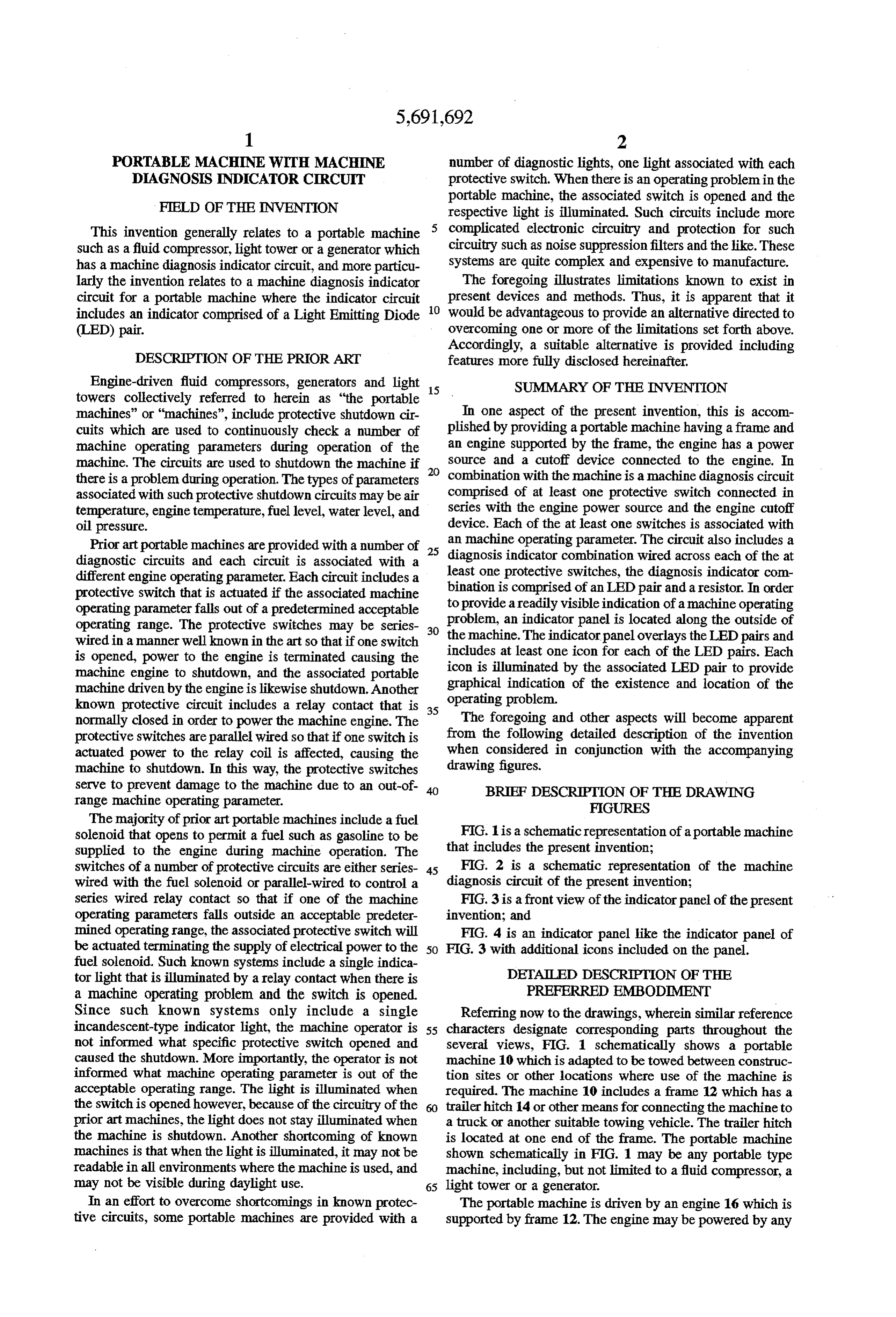
PORTABLE MACHINE WITH MACHINE number of diagnostic lights, one light associated with each DAGNOSIS INDICATOR CRCUT protective switch. When there is an operating problem in the
FIELD OF THE INVENTION
portable machine, the associated switch is opened and the respective light is illuminated. Such circuits include more
This invention generally relates to a portable machine 5 complicated electronic circuitry and protection for such such as a fluid compressor, light tower or a generator which circuitry such as noise suppression filters and the like. These has a machine diagnosis indicator circuit, and more particu systems are quite complex and expensive to manufacture. larly the invention relates to a machine diagnosis indicator The foregoing illustrates limitations known to exist in circuit for a portable machine where the indicator circuit 10 present devices and methods. Thus, it is apparent that it includes an indicator comprised of a Light Emitting Diode would be advantageous to provide an alternative directed to (LED) pair. overcoming one or more of the limitations set forth above. Accordingly, a suitable alternative is provided including
DESCRIPTION OF THE PRIOR ART features more fully disclosed hereinafter. Engine-driven fluid compressors, generators and light 15 SUMMARY OF THE INVENTION towers collectively referred to herein as "the portable machines" or "machines", include protective shutdown cir In one aspect of the present invention, this is accom cuits which are used to continuously check a number of plished by providing a portable machine having a frame and machine operating parameters during operation of the an engine supported by the frame, the engine has a power machine. The circuits are used to shutdown the machine if 20 source and a cutoff device connected to the engine. In there is a problem during operation. The types of parameters combination with the machine is a machine diagnosis circuit associated with such protective shutdown circuits may be air comprised of at least one protective switch connected in temperature, engine temperature, fuel level, water level, and series with the engine power source and the engine cutoff oil pressure. device. Each of the at least one switches is associated with Prior art portable machines are provided with a number of 25 an machine operating parameter. The circuit also includes a diagnostic circuits and each circuit is associated with a diagnosis indicator combination wired across each of the at different engine operating parameter. Each circuit includes a least one protective switches, the diagnosis indicator com protective switch that is actuated if the associated machine to bination is comprised of an LED pair and a resistor. In order operating parameterfalls out of a predetermined acceptable provide a readily visible indication of amachine operating operating range. The protective switches may be series 30 problem, an indicator panel is located along the outside of wired in a manner well known in the art so that if one switch the machine. The indicator panel overlays the LED pairs and is opened, power to the engine is terminated causing the includes at least one icon for each of the LED pairs. Each machine engine to shutdown, and the associated portable icon is illuminated by the associated LED pair to provide machine driven by the engine islikewise shutdown. Another graphical indication of the existence and location of the known protective circuit includes a relay contact that is 35 operating problem.
normally closed in order to power the machine engine. The The foregoing and other aspects will become apparent protective switches are parallel wired so that if one switch is from the following detailed description of the invention actuated power to the relay coil is affected, causing the when considered in conjunction with the accompanying machine to shutdown. In this way, the protective switches drawing figures.
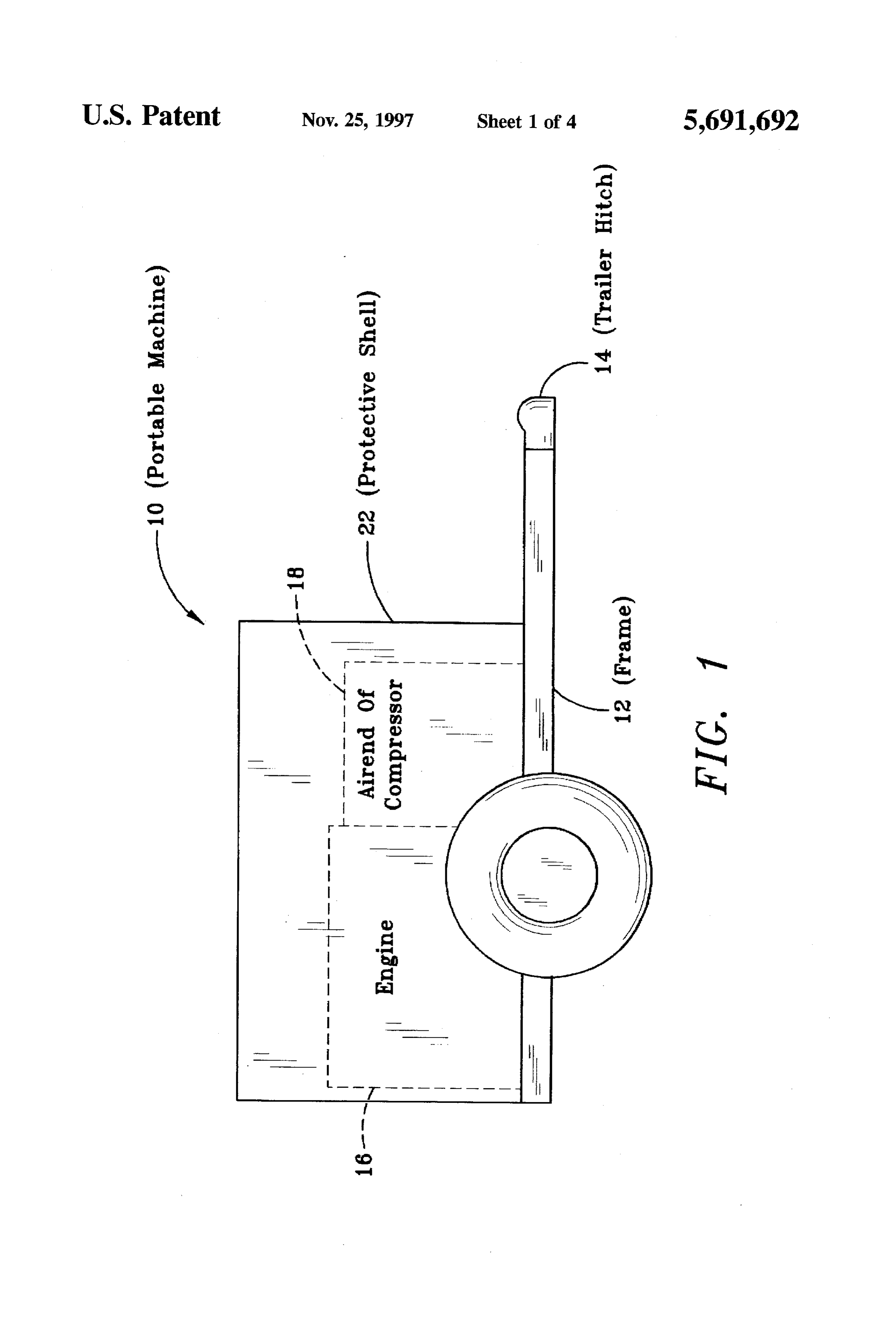
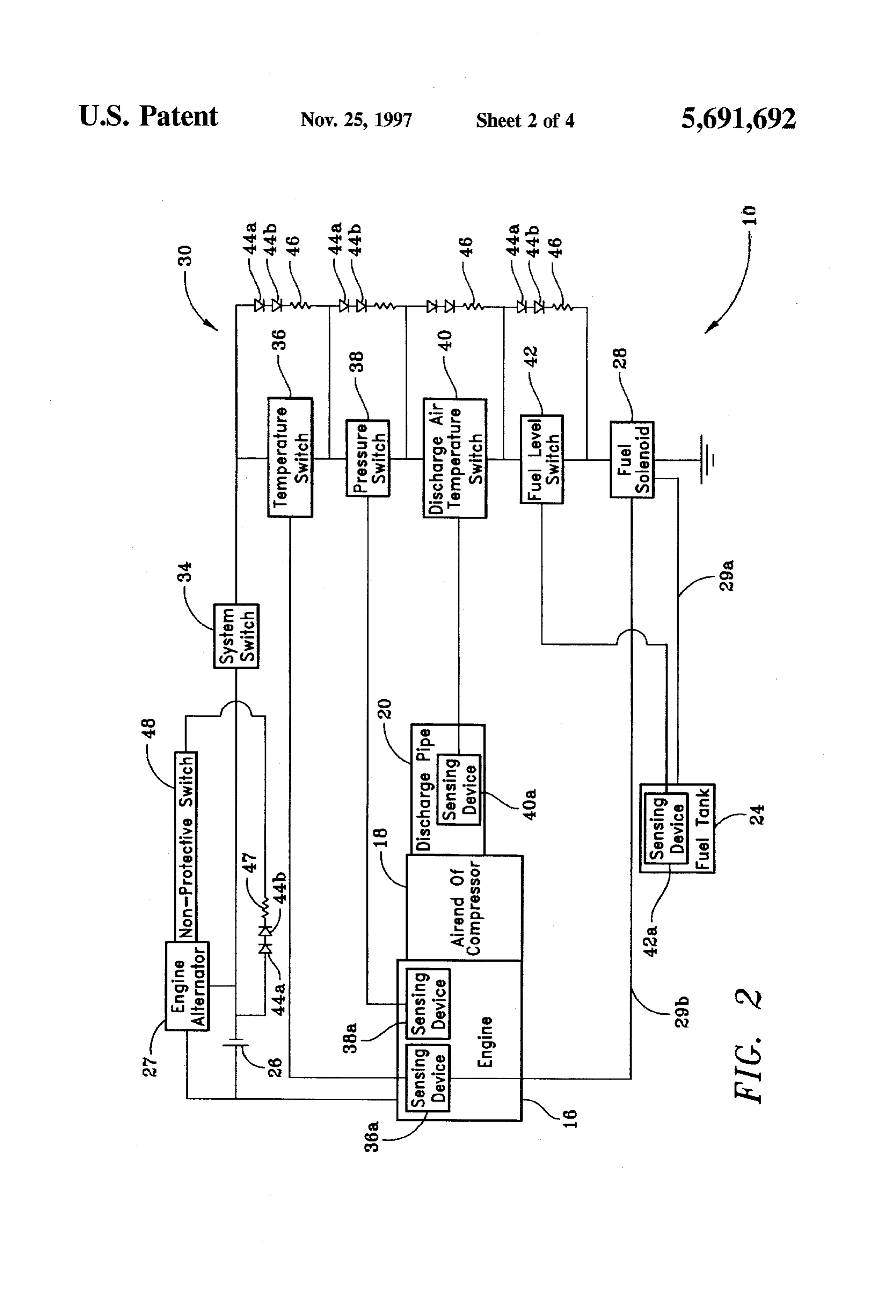
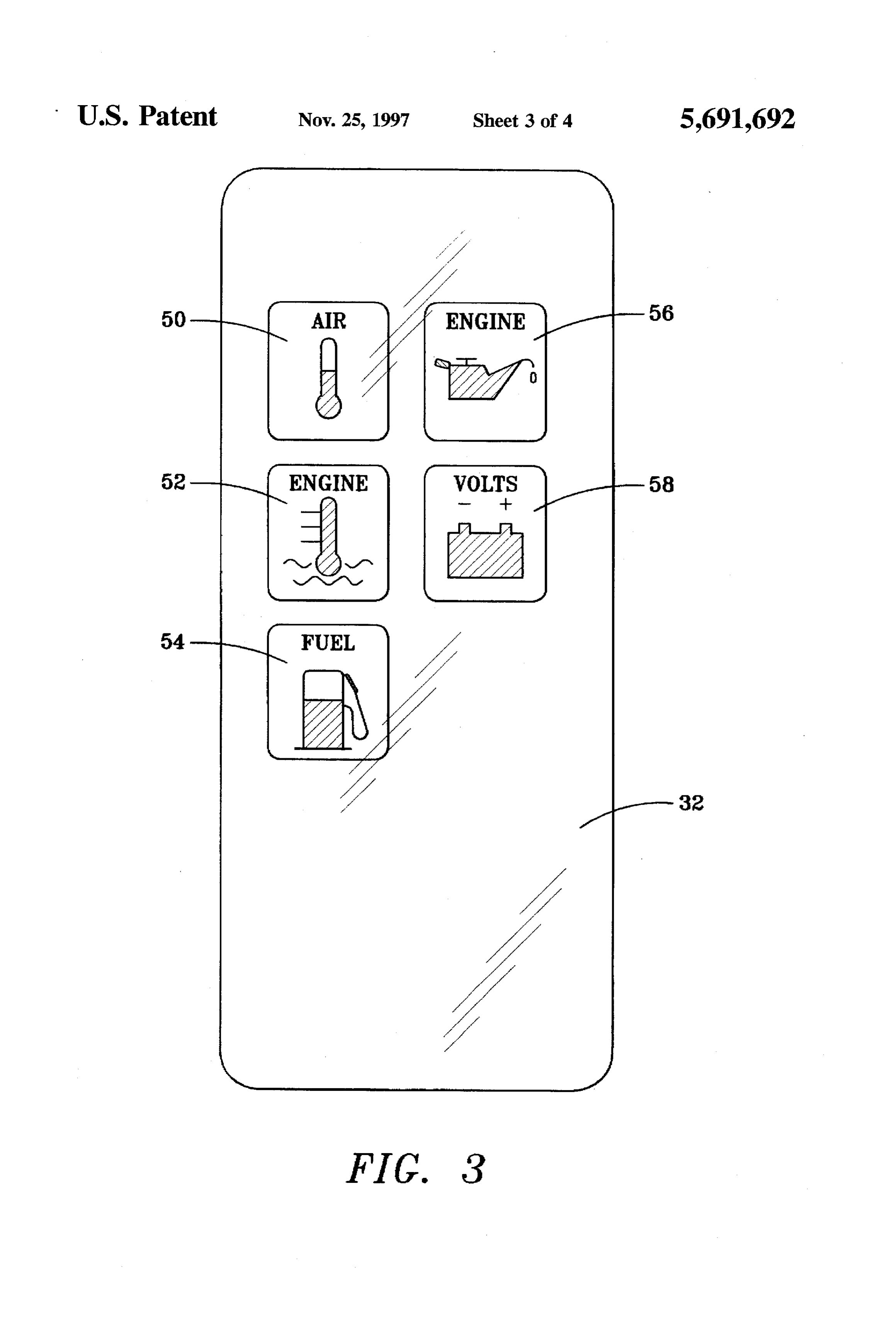
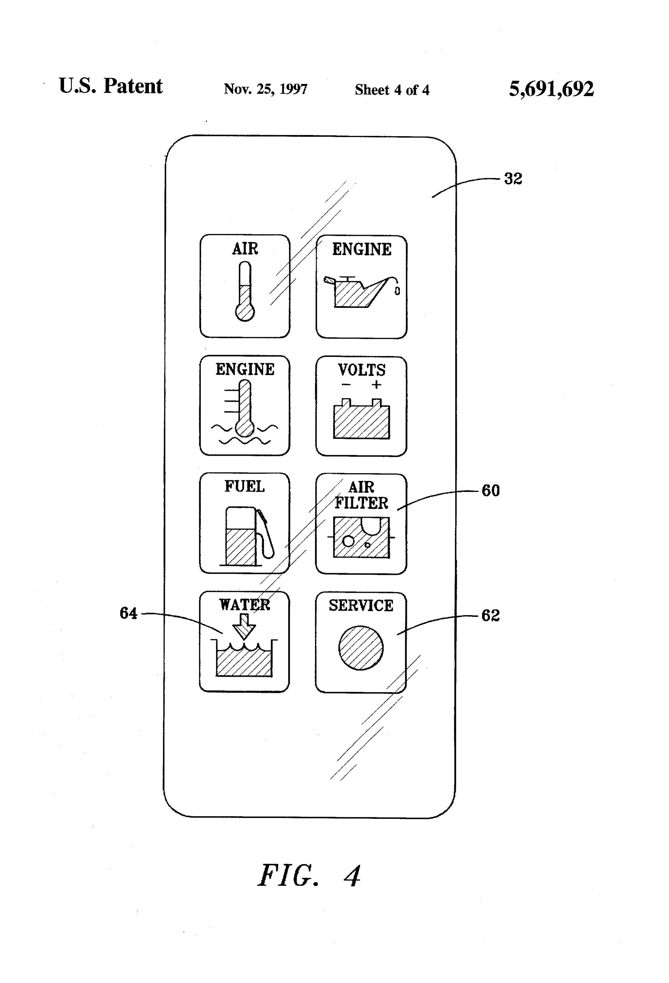
serve to prevent damage to the machine due to an out-of BRIEF DESCRIPTION OF THE DRAWING range machine operating parameter. FIGURES The majority of prior art portable machines include a fuel solenoid that opens to permit a fuel such as gasoline to be FIG. 1 is a schematic representation of a portable machine supplied to the engine during machine operation. The that includes the present invention;
switches of a number of protective circuits are either series 45 FIG. 2 is a schematic representation of the machine wired with the fuel solenoid or parallel-wired to control a diagnosis circuit of the present invention; series wired relay contact so that if one of the machine FIG. 3 is a front view of the indicator panel of the present operating parameters falls outside an acceptable predeter invention; and mined operating range, the associated protective switch will FIG. 4 is an indicator panel like the indicator panel of be actuated terminating the supply of electrical power to the 50 FIG. 3 with additional icons included on the panel. fuel solenoid. Such known systems include a single indica tor light that is illuminated by a relay contact when there is DETALED DESCRIPTION OF THE a machine operating problem and the switch is opened. PREFERRED EMBODMENT Since such known systems only include a single Referring now to the drawings, wherein similar reference incandescent-type indicator light, the machine operator is 55 characters designate corresponding parts throughout the not informed what specific protective switch opened and several views, FIG. 1 schematically shows a portable caused the shutdown. More importantly, the operator is not machine 10 which is adapted to be towed between construc informed what machine operating parameter is out of the tion sites or other locations where use of the machine is acceptable operating range. The light is illuminated when required. The machine 10 includes a frame 12 which has a the switch is opened however, because of the circuitry of the trailer hitch 14 or other means for connecting the machine to prior art machines, the light does not stay illuminated when a truck or another suitable towing vehicle. The trailer hitch the machine is shutdown. Another shortcoming of known is located at one end of the frame. The portable machine machines is that when the light is illuminated, it may not be shown schematically in FIG. 1 may be any portable type readable in all environments where the machine is used, and machine, including, but not limited to a fluid compressor, a may not be visible during daylight use. 65 light tower or a generator.
In an effort to overcome shortcomings in known protec The portable machine is driven by an engine 16 which is tive circuits, some portable machines are provided with a supported by frame 12. The engine may be powered by any
Page 7
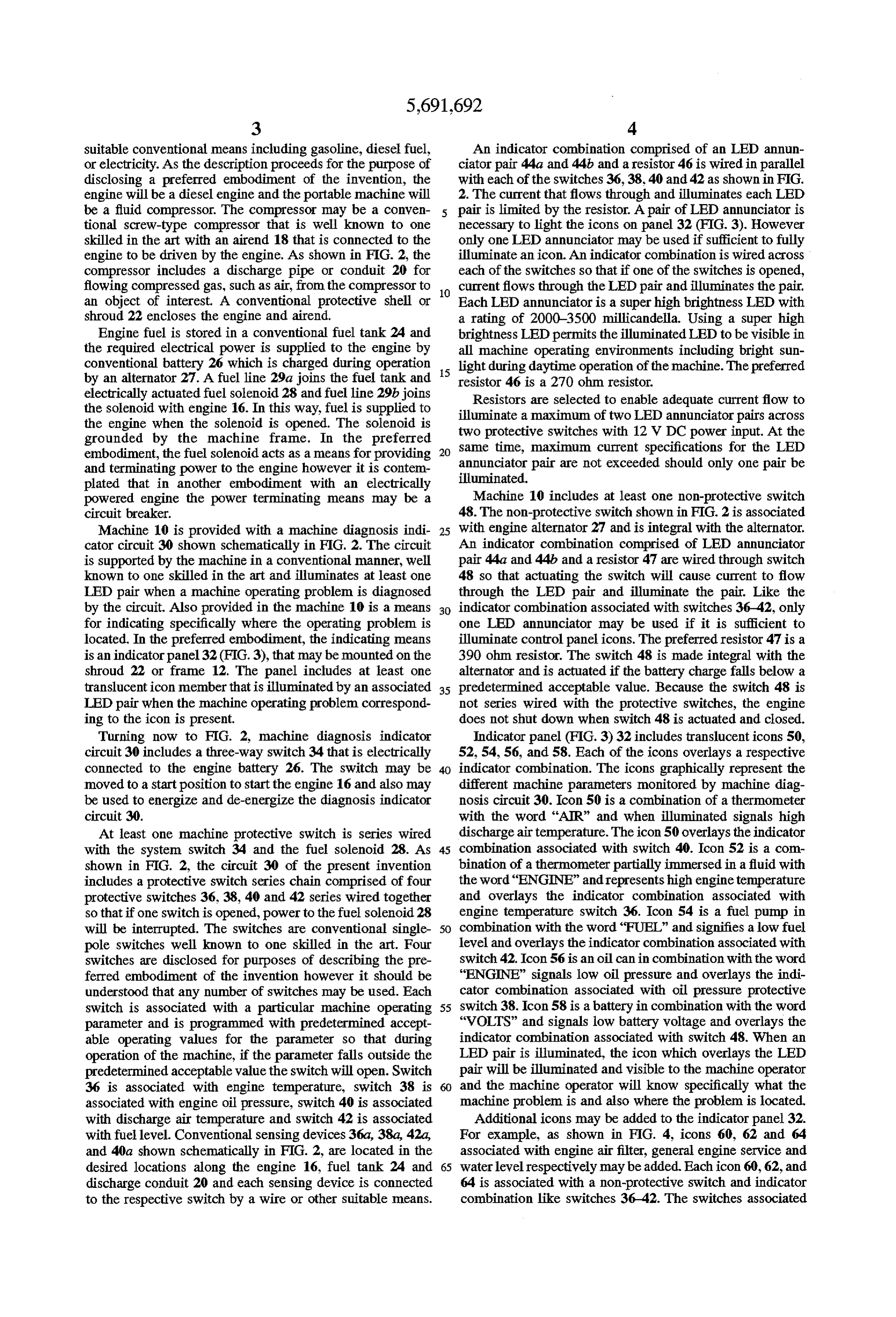
suitable conventional means including gasoline, diesel fuel, An indicator combination comprised of an LED annun or electricity. As the description proceeds for the purpose of ciator pair 44a and 44b and a resistor 46 is wired in parallel disclosing a preferred embodiment of the invention, the with each of the switches 36,38, 40 and 42 as shown in FIG. engine will be a diesel engine and the portable machine will 2. The current that flows through and illuminates each LED be a fluid compressor. The compressor may be a conven pair is limited by the resistor. A pair of LED annunciator is tional screw-type compressor that is well known to one necessary to light the icons on panel 32 (FIG. 3). However skilled in the art with an airend 18 that is connected to the only one LED annunciator may be used if sufficient to fully engine to be driven by the engine. As shown in FIG. 2, the illuminate an icon. An indicator combination is wired across compressor includes a discharge pipe or conduit 20 for each of the switches so that if one of the switches is opened, flowing compressed gas, such as air, from the compressor to 10 current flows through the LED pair and illuminates the pair. an object of interest. A conventional protective shell or Each LED annunciator is a super high brightness LED with shroud 22 encloses the engine and airend. a rating of 2000-3500 millicandella. Using a super high Engine fuel is stored in a conventional fuel tank 24 and brightness LED permits the illuminated LED to be visible in the required electrical power is supplied to the engine by all machine operating environments including bright sun conventional battery 26 which is charged during operation light during daytime operation of the machine. The preferred by an alternator 27. A fuel line 29a joins the fuel tank and 15 resistor 46 is a 270 ohm resistor. electrically actuated fuel solenoid 28 and fuel line 29b joins Resistors are selected to enable adequate current flow to the solenoid with engine 16. In this way, fuel is supplied to illuminate a maximum of two LED annunciator pairs across the engine when the solenoid is opened. The solenoid is two protective switches with 12 V DC power input. At the grounded by the machine frame. In the preferred same time, maximum embodiment, the fuel solenoid acts as a means for providing annunciator pair are notcurrent 20 specifications for the LED exceeded should only one pair be and terminating power to the engine however it is contem illuminated.
plated that in another embodiment with an electrically powered engine the power terminating means may be a Machine 10 includes at least one non-protective switch circuit breaker. 48. The non-protective switch shown in FIG. 2 is associated Machine 10 is provided with a machine diagnosis indi 25 with engine alternator 27 and is integral with the alternator. cator circuit 30 shown schematically in FIG. 2. The circuit An indicator combination comprised of LED annunciator is supported by the machine in a conventional manner, well pair 44a and 44b and a resistor 47 are wired through switch known to one skilled in the art and illuminates at least one 48 so that actuating the switch will cause current to flow LED pair when a machine operating problem is diagnosed through the LED pair and illuminate the pair. Like the by the circuit. Also provided in the machine 10 is a means 30 indicator combination associated with switches 36-42, only for indicating specifically where the operating problem is one LED annunciator may be used if it is sufficient to located. In the preferred embodiment, the indicating means illuminate control panel icons. The preferred resistor 47 is a is an indicator panel32 (FIG. 3), that may be mounted on the 390 ohm resistor. The switch 48 is made integral with the shroud 22 or frame 12. The panel includes at least one alternator and is actuated if the battery charge falls below a translucent icon member that is illuminated by an associated 35 predetermined acceptable value. Because the switch 48 is LED pair when the machine operating problem correspond not series wired with the protective switches, the engine ing to the icon is present. does not shut down when switch 48 is actuated and closed. Turning now to FIG. 2, machine diagnosis indicator Indicator panel (FIG. 3)32 includes translucenticons 50, circuit 30 includes a three-way switch 34 that is electrically 52, 54, 56, and 58. Each of the icons overlays a respective connected to the engine battery 26. The switch may be indicator combination. The icons graphically represent the moved to a start position to start the engine 16 and also may different machine parameters monitored by machine diag be used to energize and de-energize the diagnosis indicator nosis circuit 30. Icon 50 is a combination of a thermometer circuit 30. with the word "AIR” and when illuminated signals high At least one machine protective switch is series wired discharge air temperature. The icon 50 overlays the indicator with the system switch 34 and the fuel solenoid 28. As 45 combination associated with switch 40. Icon 52 is a com shown in FIG. 2, the circuit 30 of the present invention bination of a thermometer partially immersed in a fluid with includes a protective switch series chain comprised of four the word “ENGINE” and represents high engine temperature protective switches 36, 38, 40 and 42 series wired together and overlays the indicator combination associated with so that if one switch is opened, power to the fuel solenoid 28 engine temperature switch 36. Icon 54 is a fuel pump in will be interrupted. The switches are conventional single 50 combination with the word “FUEL" and signifies a low fuel pole switches well known to one skilled in the art. Four level and overlays the indicator combination associated with switches are disclosed for purposes of describing the pre switch 42. Icon 56 is an oil can in combination with the word ferred embodiment of the invention however it should be "ENGINE" signals low oil pressure and overlays the indi understood that any number of switches may be used. Each cator combination associated with oil pressure protective switch is associated with a particular machine operating 55 switch 38. Icon 58 is a battery in combination with the word parameter and is programmed with predetermined accept "VOLTS" and signals low battery voltage and overlays the able operating values for the parameter so that during indicator combination associated with switch 48. When an operation of the machine, if the parameter falls outside the LED pair is illuminated, the icon which overlays the LED predetermined acceptable value the switch will open. Switch pair will be illuminated and visible to the machine operator 36 is associated with engine temperature, switch 38 is and the machine operator will know specifically what the associated with engine oil pressure, switch 40 is associated machine problem is and also where the problem is located. with discharge air temperature and switch 42 is associated Additional icons may be added to the indicator panel 32. with fuel level. Conventional sensing devices 36a, 38a, 42a, For example, as shown in FIG. 4, icons 60, 62 and 64 and 4.0a shown schematically in FIG. 2, are located in the associated with engine air filter, general engine service and desired locations along the engine 16, fuel tank 24 and 65 water level respectively may be added. Each icon 60, 62, and discharge conduit 20 and each sensing device is connected 64 is associated with a non-protective switch and indicator to the respective switch by a wire or other suitable means. combination like switches 36–42. The Switches associated
Page 8
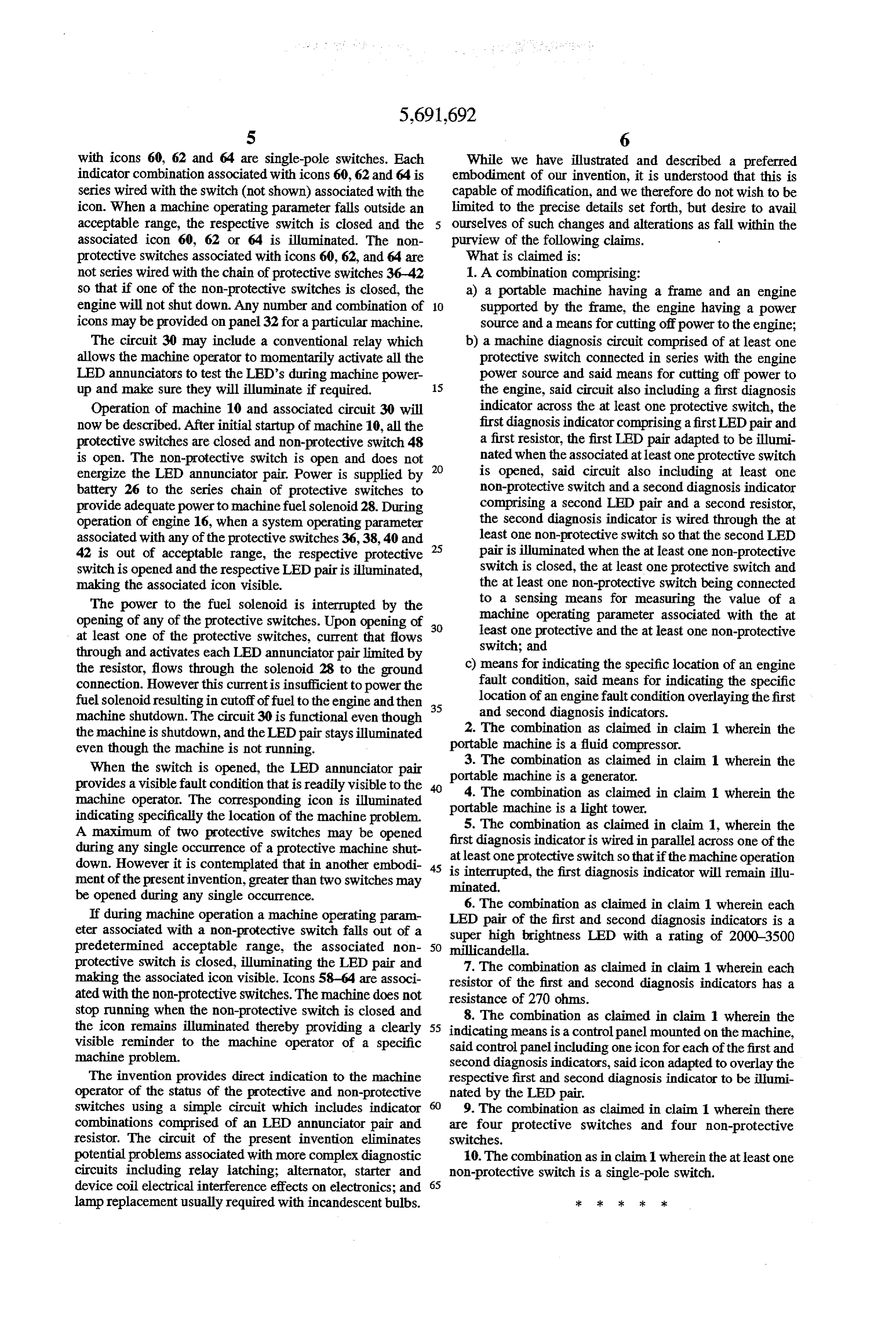
with icons 60, 62 and 64 are single-pole switches. Each While we have illustrated and described a preferred indicator combination associated with icons 60, 62 and 64 is embodiment of our invention, it is understood that this is series wired with the switch (not shown) associated with the capable of modification, and we therefore do not wish to be icon. When a machine operating parameter falls outside an limited to the precise details set forth, but desire to avail acceptable range, the respective switch is closed and the ourselves of such changes and alterations as fall within the associated icon 60, 62 or 64 is illuminated. The non purview of the following claims.
protective switches associated with icons 60, 62, and 64 are What is claimed is:
not series wired with the chain of protective switches 36-42 1. A combination comprising:
so that if one of the non-protective switches is closed, the a) a portable machine having a frame and an engine engine will not shut down. Any number and combination of 10 supported by the frame, the engine having a power icons may be provided on panel 32 for a particular machine, source and a means for cutting off power to the engine; The circuit 30 may include a conventional relay which b) a machine diagnosis circuit comprised of at least one allows the machine operator to momentarily activate all the protective switch connected in series with the engine LED annunciators to test the LED's during machine power power source and said means for cutting off power to up and make sure they will illuminate if required. 15 the engine, said circuit also including a first diagnosis Operation of machine 10 and associated circuit 30 will indicator across the at least one protective switch, the now be described. After initial startup of machine 10, all the first diagnosis indicator comprising a first LED pair and protective switches are closed and non-protective switch 48 a first resistor, the first LED pair adapted to be illumi is open. The non-protective switch is open and does not 20 nated when the associated at least one protective switch energize the LED annunciator pair. Power is supplied by is opened, said circuit also including at least one battery 26 to the series chain of protective switches to non-protective switch and a second diagnosis indicator provide adequate power to machine fuel solenoid 28. During comprising a second LED pair and a second resistor, operation of engine 16, when a system operating parameter the second diagnosis indicator is wired through the at associated with any of the protective switches 36,38, 40 and 25 least one non-protective switch so that the second LED 42 is out of acceptable range, the respective protective pair is illuminated when the at least one non-protective switch is opened and the respective LED pairis illuminated, switch is closed, the at least one protective switch and making the associated icon visible. the at least one non-protective switch being connected The power to the fuel solenoid is interrupted by the to a sensing means for measuring the value of a opening of any of the protective switches. Upon opening of 30 machine operating parameter associated with the at at least one of the protective switches, current that flows least one protective and the at least one non-protective through and activates each LED annunciator pair limited by switch; and the resistor, flows through the solenoid 28 to the ground c) means for indicating the specific location of an engine connection. However this currentis insufficient to power the fault condition, said means for indicating the specific fuel solenoid resulting in cutoff of fuel to the engine and then 35 location of an engine fault condition overlaying the first machine shutdown. The circuit 30 is functional even though and Second diagnosis indicators. the machine is shutdown, and the LED pair stays illuminated portable 2. The combination as claimed in claim 1 wherein the even though the machine is not running. machine is a fluid compressor. 3. The combination as claimed in claim 1 wherein the
When the switch is opened, the LED annunciator pair provides a visible fault condition that is readily visible to the portable machine is a generator. 4. The combination as claimed in claim 1 wherein the machine operator. The corresponding icon is illuminated indicating specifically the location of the machine problem. portable 5. The machine is a light tower.
combination as claimed in claim 1, wherein the
A maximum of two protective switches may be opened during any single occurrence of a protective machine shut first diagnosis indicatoris wired in parallel across one of the down. However it is contemplated that in another embodi 45 isat least one protective switch so that if the machine operation interrupted, the first diagnosis indicator will remain illu ment of the presentinvention, greater than two switches may minated.
be opened during any single occurrence. 6. The combination as claimed in claim 1 wherein each If during machine operation a machine operating param LED pair of the first and second diagnosis indicators is a eter associated with a non-protective switch falls out of a predetermined acceptable range, the associated non 50 super high brightness LED with a rating of 2000-3500 millicandella.
protective switch is closed, illuminating the LED pair and 7. The combination as claimed in claim 1 wherein each making the associated icon visible. Icons 58-64 are associ resistor of the first and second diagnosis indicators has a ated with the non-protective switches. The machine does not resistance of 270 ohms.
stop running when the non-protective switch is closed and 8. The combination as claimed in claim 1 wherein the the icon remains illuminated thereby providing a clearly 55 indicating means is a control panel mounted on the machine, visible reminder to the machine operator of a specific said control panel including one icon for each of the first and machine problem. second diagnosis indicators, said icon adapted to overlay the The invention provides direct indication to the machine respective first and second diagnosis indicator to be illumi operator of the status of the protective and non-protective nated by the LED pair.
switches using a simple circuit which includes indicator 9. The combination as claimed in claim 1 wherein there combinations comprised of an LED annunciator pair and are four protective switches and four non-protective resistor. The circuit of the present invention eliminates switches.
potential problems associated with more complex diagnostic 10. The combination as in claim.1 wherein the at least one circuits including relay latching; alternator, starter and non-protective switch is a single-pole switch. device coil electrical interference effects on electronics; and 65 lamp replacement usually required with incandescent bulbs. ; : k :: *k
Provenance
- Collection
- Cited prior art
- Original PDF
- patentimages.storage.googleapis.com →
- Filed
- 1996-01-25
- Pages
- 8
- Method
- pdftotext (the PDF's own text layer) + pdftoppm 300dpi page scans
- Source
- Google Patents bibliographic record
- Granted
- 1997-11-25
- Inventors
- Dale R. Herbstritt; Ingersoll Rand Co
- Transcribed from
- patentimages.storage.googleapis.com →