patent · US5370097
Combined diesel and natural gas engine fuel control system and method of using such
6 December 1994
Page 1 — bibliographic record
United States Patent (19) 11 Patent Number: 5,370,097 Davis 45 Date of Patent: Dec. 6, 1994 54 COMBINED DESEL AND NATURAL GAS 4,831,993 5/1989 Kelgard .............................. 123/525 ENGINE FUEL CONTROL SYSTEMAND 4,955,326 9/1990 Helmich .. 123/27 GE METHOD OF USNG SUCH 5,083,547 1/1992 Davis .................................. 123/527 5,092,305 3/1992 King ... 123/27 GE
I75 Inventor: Frank J. Davis, Riverdale, Ga. 5,103,795 4/1992 Davis .................................. 123/527 5,136,986 8/1992 Jensen ............................ 123/27 GE (73) Assignee: Davis Family Trust, Atlanta, Ga.
FOREIGN PATENT DOCUMENTS
22) Filed: Mar. 22, 1993 0168036 10/1982 Japan ................................... 123/525 51 Int. Cl: ............................................. F02M 21/02 Primary Examiner-E. Rollins Cross (52) - - - - 123/526; 123/27 GE Assistant Examiner-Erick Solis 58 Field of Search .................. 123/575,526, 27 GE, Attorney, Agent, or Firm-Kennedy & Kennedy 123/525, 198 D, 198 DB, 357 57 ABSTRACT
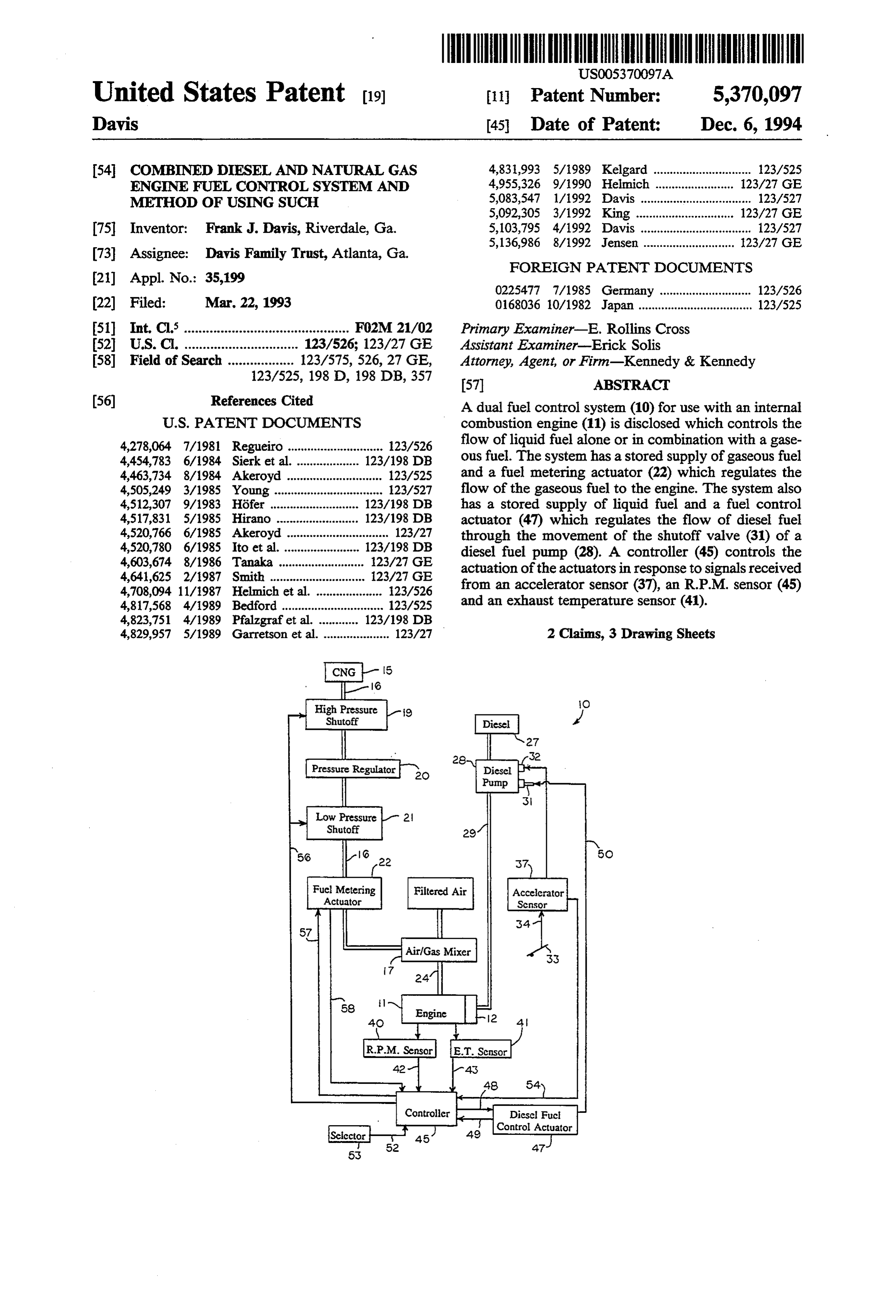
A dual fuel control system (10) for use with an internal
4,278,064 7/1981 Regueiro ............................. 123/526 flow of liquid fuel alone or in combination with a gase 4,454,783 6/1984 Sierk et al. ... 123/198 DB ous fuel. The system has a stored supply of gaseous fuel 4,463,734 8/1984 Akeroyd ............................. 123/525 and a fuel metering actuator (22) which regulates the 4,505,249 3/1985 Young ................................. 123/527 flow of the gaseous fuel to the engine. The system also 4,512,307 9/1983 Hofer ....... 123/198 DB has a stored supply of liquid fuel and a fuel control
a- ......... 123/198 DB actuator (47) which regulates the flow of diesel fuel 4,520,766 6/1985 Akeroyd ............................... 123/27 through the movement of the shutoff valve (31) of a 4,520,780 6/1985 to et al.... . 123/198 DB diesel fuel pump (28). A controller (45) controls the 4,603,674 8/1986 Tanaka .......................... 23/27 GE actuation of the actuators in response to signals received 4,641,625 2/1987 Smith ............... ... 123/27 GE 4,708,094 11/1987 Helmich et al. .................... 23/526 from an accelerator sensor (37), an R.P.M. sensor (45) 4,817,568 4/1989 Bedford ............................... 123/525 and an exhaust temperature sensor (41). 4,823,751 4/1989 Pfalzgraf et al. ... 123/198 DB 4,829,957 5/1989 Garretson et al. .................... 123/27 2 Claims, 3 Drawing Sheets
Fuel Meteriing
Actuator
Diesel Fuct
Control Actuator
Page 2
Drawing sheet — no readable text.
Page 3
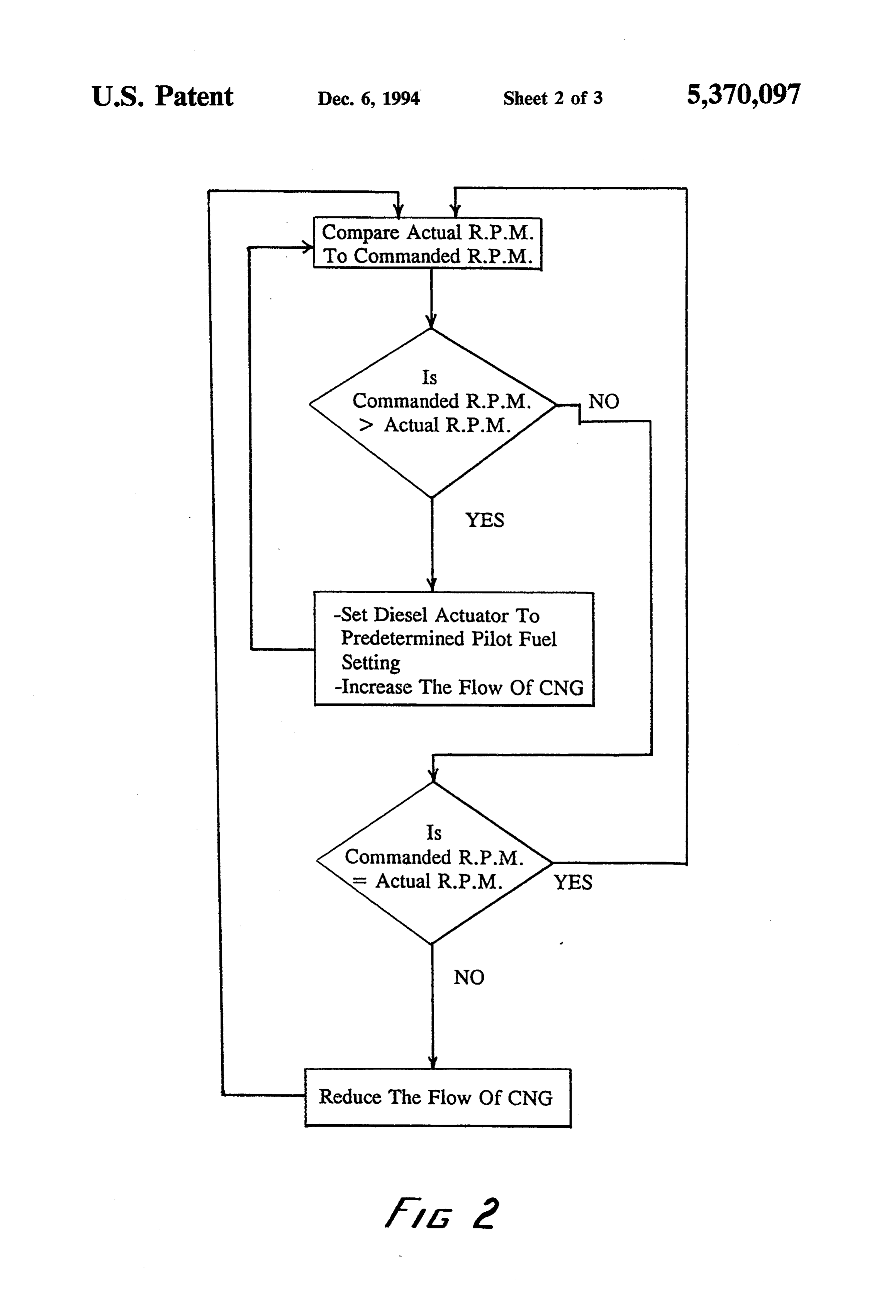
Compare Actual R.P.M. To Commanded R.P.M.
Commanded R.P.M.
D Actual R.P.M.
-Set Diesel Actuator To Predetermined Pilot Fuel Setting -Increase The Flow Of CNG
Commanded R.P.M.
s Actual R.P.M. YES Reduce The Flow Of CNG MVZ 2
Page 4
Drawing sheet — no readable text.
Page 5
also has engine speed sensing means for sensing the
COMBINED DESEL AND NATURAL GAS speed of the engine, engine throttle position sensing ENGINE FUEL CONTROL SYSTEMAND means for sensing the position of the throttle, and con METHOD OF USNG SUCH trol means for controlling the liquid fuel metering means and the gaseous fuel metering means in response
TECHNICAL FIELD to comparisons of the sensed engine speeds with sensed This invention relates to fuel control systems and throttle positions in accordance with predetermined methods for using such for internal combustion engines metering settings for given engine speeds. which may operate on a combination of two fuels. In another preferred form of the invention, a method O of controlling the flow of a gaseous fuel and the flow of
BACKGROUND OF THE INVENTION diesel fuel into a diesel engine comprises the steps of The air pollution problems inherent in the operation continuously sensing actual engine speeds and con of gasoline fueled and diesel oil fueled internal combus manded engine speeds and metering the flow of gaseous tion engines are well known. For this reason various 15 fuel and the flow of diesel fuel into the engine in propor emission control devices are presently in use, and in tions relative to sensed differences between the actual deed are required by federal regulations, to reduce the engine speeds and commanded engine speeds. amount of pollutants discharged into the atmosphere by BRIEF DESCRIPTION OF THE DRAWING internal combustion engines. These emission control devices, however, only remove a portion of the pollut FIG. 1 is a schematic diagram of a system embodying ants and are subject to deterioration with the passage of principles of the present invention. time. Also, they often hinder engines from operating at FIG. 2 is a flow diagram by which the controller of peak efficiencies. the system of FIG. 1 regulates the flow of each fuel. Natural gas is also sometimes used as a fuel for inter FIG. 3 is a graph showing proportional amounts of nal combustion engines. It has the capability of produc fuels dispensed by the system of FIG. 1 at various en ing less combustion pollutants and decreasing engine 25 gine speeds at a constant load.
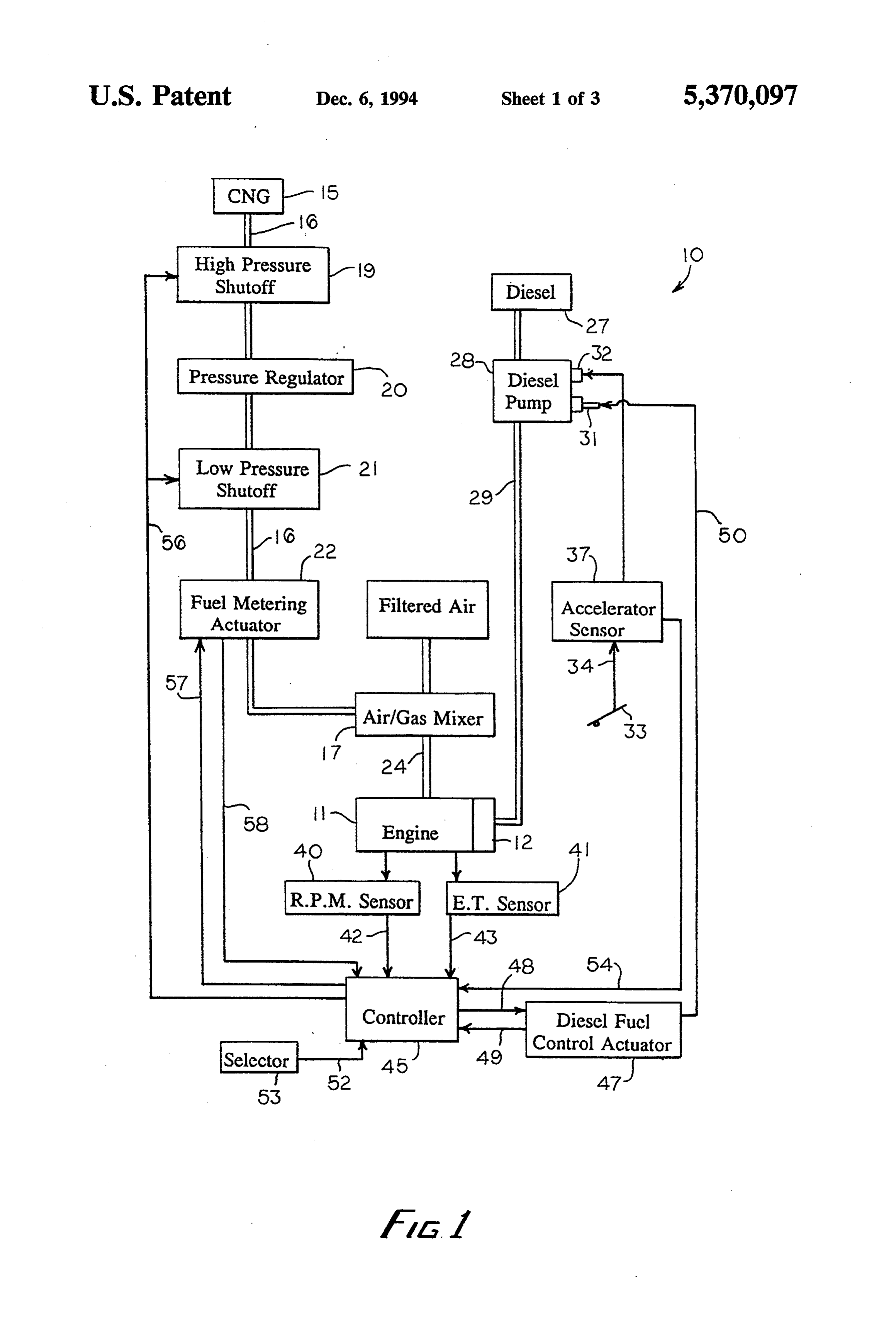
operating costs without complex emission control de vices. Obviously, its use would also reduce the rate of DETAILED DESCRIPTION world fossil fuel consumption. With reference next to the drawing, there is shown a As the transportation infrastructure of today in the combined liquid fuel and gaseous fuel control system 10 United States does not include large numbers of widely 30 for use in supplying disbursed retail suppliers of natural gas for vehicles, it is with a gaseous fuel toliquid
fuel alone or in combination internal combustion engine 11 not practical to produce vehicles that are fueled solely having fuel injectors 12. Fuel injectors 12 are pump-like by gaseous fuels like natural gas due to range limita devices which inject fuel directly into the cylinders of tions. To evolve towards such it is more practical to equip vehicles with a supply of both a liquid fuel such as 35 the engine. The liquid fuel is hereinafter referred to as diesel fuel while the gaseous fuel is hereinafter referred gasoline or diesel fuel and an auxiliary supply of gaseous fuel such as natural gas. To do that efficiently it is essen to as natural gas. However, it should be understood that while it is the preferred embodiment which uses gase tial that as little retrofitting be done as possible to exist ous fuel such as natural gas or propane, a non-gaseous ing fuel intake systems and configurations.
Various systems have been developed for mixing fuel such as liquid natural gas may also be utilized. gaseous fuels with liquid fuels. For example, systems The system 10 has a high pressure gas storage tank 15 have been designed which entrain gaseous fuel through which supplies compressed natural gas (CNG) through a gas metering valve into air supplied to the air inlet a conduit 16 to an air/gas mixer 17 mounted to induce manifold of a diesel engine. This combination of air and natural gas into an airstream entering the air intake of fuel is then mixed with the diesel fuel prior to combus 45 the engine 11. The air/gas mixer 17 may be a model tion. Exemplary of this type of system is that shown in SP4D of Combustion Lab's Inc. of Riverdale, Ga. A U.S. Pat. No. 4,463,734. Since these systems control the high pressure shutoff valve 19, a pressure regulator 20, flow of gaseous fuel by the volume of air entering the a low pressure shutoff valve 21 and a fuel metering engine, there is a direct and constant gaseous fuel to actuator 22 are coupled in series to the conduit 16 be diesel fuel ratio. However, because different load condi 50 tween the tank 15 and the mixer 17 to control the flow tions can occur at various engine speeds, this type of of the natural gas. The pressure regulator 20 reduces the system does not always provide a mixture which results pressure of the natural gas to a selected pressure, de in maximum efficiency. pending upon the type and size of engine used with the It thus is seen that a system for controlling the flow of system 10. The fuel metering actuator 22 may be a gaseous fuel and the flow of liquid fuel into an internal 55 model DYNK 10322-800 of Barber Colman Company combustion engine to provide the maximum efficiency of Loves Park, Ill. Filtered air from ambience is sup and output has remained an elusive goal. Accordingly, plied to the mixer 17 through a conduit 24. it is to the provision of such that the present invention is The system 10 also has a diesel fuel storage tank 27 primarily directed. coupled to a fuel pump 28 which supplies diesel fuel
SUMMARY OF THE INVENTION
through a conduit 29 to the engine fuel injectors 12. As fuel pump 28 is driven by the engine, its output is in
In a preferred form of the invention, a dual fuel con direct relationship to the speed of the engine. The fuel trol system for use with an internal combustion engine pump 28 has an unshown mechanical governor, a shut having a throttle is provided having a liquid fuel meter off lever 31 and a throttle 32. The shutoff lever 31 is ing means for metering the flow of liquid fuel, air/fuel 65 used in an unconventional manner so as to limit the flow mixer means for mixing liquid fuel metered to the en of diesel fuel pumped by pump 28just as does the throt gine with air, and gaseous fuel metering means for me tle 32. The effective use of two throttles is employed to tering the flow of gaseous fuel to the engine. The system prevent diesel fuel from entering the engine when the
Page 6
engine is not operating. The throttle 32 is coupled to an OPERATION accelerator pedal 33 by a movable cable 34. An acceler ator sensor 37 is employed to sense the position of the With the controller 45 preprogrammed with a map manual accelerator pedal 33 and thereby the throttle 32. ping of the engine's torque and horsepower for each Tank 27, pump 28, conduit 29, throttle 32, shutoff lever engine speed, the controller regulates the flows of diesel 31, accelerator pedal 33 and cable 31 are, per se, stan fuel and natural gas in a manner which does not surpass dard equipment on automobiles having diesel engines. the mapped conditions so as to overpower the engine. An engine speed or R.P.M. sensor 40 and an exhaust In other words, the combination of the two fuels does temperature sensor 41 are coupled with the engine 11 not produce an engine torque or horsepower greater and with a controller 45 by means of signal lines 42 and O than that produced by the engine conventionally oper 43 respectively. The controller 45 is coupled to a diesel ating on diesel fuel only. With the ignition of the engine fuel control actuator 47 by signal output line 48 and a 11 turned off the natural gas shutoff valves 19 and 21 feedback line 49. The diesel fuel control actuator 47 is in and the diesel pump shutoff lever 31 are closed so that turn mechanically coupled to the shutoff lever 31 by a neither natural gas nor diesel fuel may enter the engine. cable 50. A bi-positional fuel selector 53 is provided that 15 To start and operate the engine 11 solely on diesel is coupled to the controller 45 by a signal line 52. The fuel the selector 53 is positioned off. With the selector in controller 45 is also coupled to both the shutoff valves this position the shutoff valves 19 and 21 remain closed 19 and 21 by control line 56, to the fuel metering actua so as to prevent natural gas from entering the engine. As tor 22 by a control line 57 and by feedback line 58, and the ignition system of the engine is activated the shutoff finally with the accelerator sensor 37 by a line 54. 20 lever 31 is fully opened so that diesel pump 28 may force diesel fuel through conduit 29 into the injectors 12
INITIALIZING SYSTEM of the engine. The flow rate of the diesel fuel supplied to To initially set the system the selector 53 is positioned the engine is conventionally determined by the mechan “off” so that the engine operates on diesel fuel only. The ical governor and the position of the throttle 32. Air engine is then operated with the fuel pump shutoff lever 25 used in combination with the diesel fuel enters the en 31 fully opened and with the throttle 32 fully opened by gine through the air/gas mixer 17. actuator 47 so as to bring the engine to its maximum To start and operate the engine with the fuel system engine speed. A load is then placed upon the engine, as 10 in a dual fuel mode the selector 53 is selectively with a conventional dynamometer, to reduce the engine positioned on, thereby energizing controller 45. While speed by a predetermined incremental amount, typi 30 starting the engine it is undesirable to have natural gas cally about 200 r.p.m. The engine's torque, horsepower entering it, as this may cause the engine to "lock up' and exhaust temperature is next determined by the dy due to the pressure within the cylinders. Therefore, namometer and stored within the memory of the con should the R.P.M. sensor 40 indicate that the engine is troller 45. The engine is incrementally lugged down by not operating above a preselected minimum speed the the predetermined increment until it ceases to operate 35 controller 45 signals the shutoff valves 19 and 21 to due to the load on the engine. At each incremental remain closed. Once the engine is operating above the engine speed the dynamometer determines the resultant preselected minimum speed, the controller 45 energizes maximum engine torque, horsepower and exhaust tem the diesel fuel control actuator 47 and opens shutoff perature which is stored in the controller memory. This valves 19 and 21 to allow natural gas through the pres process is commonly referred to as "mapping' an en sure regulator 20 and metering actuator 22. gine. The quantity of each fuel supplied to the engine is Next, the selector 53 is positioned “on” so that the determined by the controller 45 which does so by regu engine operates on both diesel fuel and natural gas. The lating the flow of natural gas through the fuel metering engine is brought to idle with the shutoff lever 31 fully actuator 22 and the flow of diesel fuel from pump 28, opened. The shutoff lever is then slowly closed by the 45 which is determined by the selective positioning of its action of actuator 47 so as to restrict the flow of diesel throttle 32 and shutoff lever 31. The controller regu fuel therethrough while simultaneously the action of lates the flows primarily in response to information fuel metering actuator 22 increases the flow of natural provided by the R.P.M. sensor 40 and the accelerator gas therethrough to compensate for the reduction in sensor 37.
diesel fuel. The actuators 22 and 47 are moved in this 50 As shown in FIG. 2, the controller 45 determines the manner until the engine speed cannot be maintained due position of actuators 22 and 47 by first comparing the to a below minimal quantity of diesel fuel for combus commanded engine speed, which is the sensed position tion. This minimal amount of diesel fuel is commonly of the accelerator pedal 33 through accelerator sensor referred to as the "pilot fuel'. The position of the actua 37, to the actual engine speed, which is the sensed en tor 47 and the engine speed are stored in the controller 55 gine speed through R.P.M. sensor 40. This comparison memory. is performed continuously and rapidly by the controller The shutoff lever 31 is then returned to a fully opened to provide optimal efficiency.
position and the throttle 32 is moved to a position which If the commanded engine speed is greater than the increases the engine speed, by the predetermined incre actual engine speed, i.e. the condition where a load has mental amount, to the next engine speed which was 60 been placed on the engine, the controller 45 decreases previously mapped. The actuators 22 and 47 are again the flow of diesel fuel while increasing the flow of natu moved, as previously discussed, to determine and store ral gas. The controller decreases the flow of the diesel the pilot fuel position of the actuator 47 for this particu fuel by actuating the diesel fuel control actuator 47 to its lar engine speed. This process is repeated along the predetermined pilot fuel position stored in the control entire range of engine speeds at each previously stored 65 ler memory for that particular engine speed. The posi engine speed. It has been found that at a minimum the tion of the actuator 47 is confirmed through feedback pilot fuel amounts to approximately 5% of the total line 49. This positioning of the actuator 47 causes the quantity of fuels. shutoff lever 31 to close thereby restricting the flow of
Page 7
diesel fuel to its minimum acceptable level. The control mined setting since the combustion of diesel fuel pro ler increases the flow of natural gas by actuating the fuel duces less heat than the combustion of natural gas. metering actuator 22 to a metering position which in It thus is seen that a dual fuel control system is now creases the flow of natural gas therethrough. The me provided for use with an internal combustion engine tering position of actuator 22 is confirmed through which enhances efficiency. It should be understood, feedback line 58. Should feedback lines 49 and 58 not however, that the just described embodiment merely indicate a confirmed position there is a malfunction in illustrates principles of the invention in its preferred the system to be corrected. form. Many modifications, additions and deletions may, If the commanded engine speed is less than the actual 10 of course, be made thereto without departure from the engine speed, i.e. the condition where a load has been lowingandclaims.
spirit scope of the invention as set forth in the foll removed from the engine, the fuel pump mechanical I claim:
governor automatically decreases the flow of diesel. 1. A dual fuel control system for use with an internal However, the diesel fuel must be maintained at least at combustion engine having a fuel pump having a throttle its pilot fuel level. Therefore, if needed the controller 5 and a fuel shutoff lever which, in combination, limits the increases the flow of diesel fuel while decreasing the flow of liquid fuel pumped by the fuel pump compris flow of natural gas. The controller increases the flow of ing, in combination, the diesel fuel by incrementally actuating the diesel fuel liquid fuel metering means for metering the flow of control actuator 47 to a position whereby the shutoff liquid fuel, said liquid fuel metering means includ lever 31 is moved so as to allow a greater flow there 20 ing throttle metering means for metering the flow through. The controller decreases the flow of natural of liquid fuel through actuation of the throttle and gas by incrementally actuating the fuel metering actua shutoff lever metering means for metering the flow tor 22 to a metering position which decreases the flow of liquid fuel through actuation of the shutoff lever of natural gas therethrough. These incremental move in cooperation with said throttle metering means; ments continue until the commanded engine speed 25 air/fuel mixer means for mixing gaseous fuel metered equals the actual engine speed. to the engine with air;
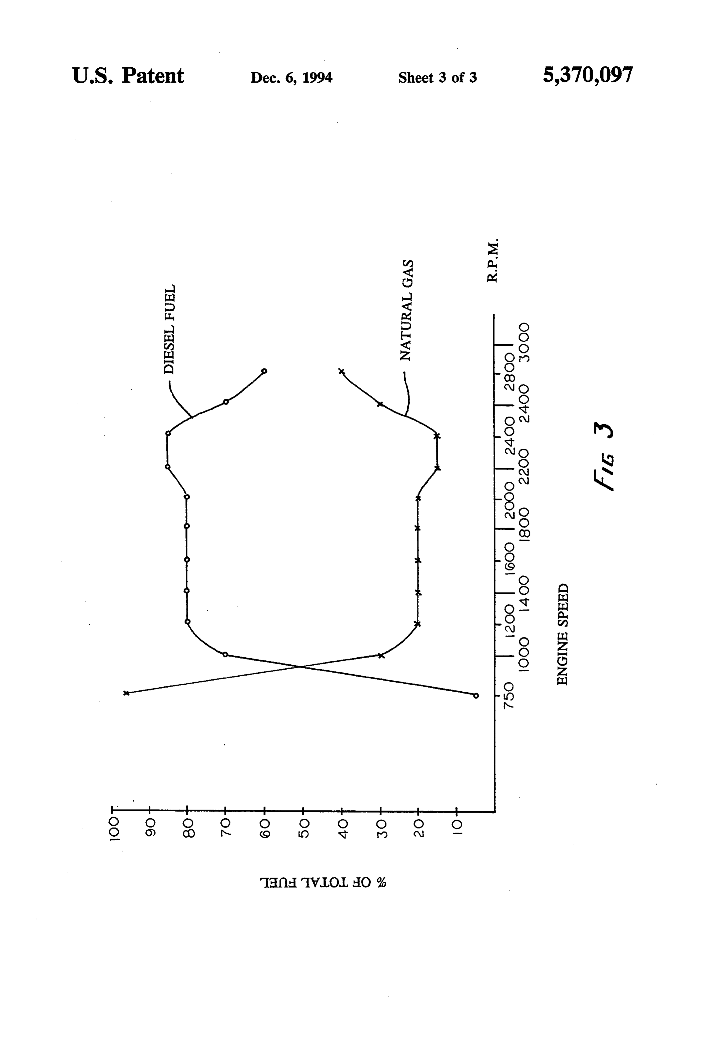
FIG. 2 plots the percentage of each fuel used along gaseous fuel metering means for metering the flow of the entire operational range of a Cummins 4BT engine. gaseous fuel to the engine; At idle the engine speed is very low with only a very engine speed sensing means for sensing the speed of small load on it. Therefore, the controller supplies the the engine;
engine with a large amount of diesel fuel and only a engine throttle position sensing means for sensing the small amount of natural gas. As the engine speed in position of the throttle; and creases an increasing amount of horsepower and torque control means for controlling said throttle metering is required. Therefore, the proportional flow of diesel 35 means, said shutoff lever metering means and said fuel is reduced while the proportional flow of natural gaseous fuel metering means in response to com parisons of the sensed engine speeds with sensed gas is increased. As previously discussed, the exact throttle positions in accordance with predeter amount of diesel fuel is determined by the predeter mined metering settings for given engine speeds mined mapping programmed that has been stored in the throughout the operable range of engine speeds. controller memory for given engine speeds. 2. The dual fuel control system of claim 1 further Should the engine overheat the exhaust temperature comprising engine temperature sensing means for sens sensor 41 indicates such a condition to the controller 45. ing the temperature of the engine, and wherein said The controller then overrides the mapped setting for control means further controls said throttle metering the flow of diesel fuel and automatically increases the means, said shutoff lever metering means and said gase flow of diesel fuel while simultaneously decreasing the 45 ous fuel metering means in response to the sensed en flow of natural gas. This combination of fuel should gine temperature.
reduce the engine temperature to below the predeter : : :
Provenance
- Collection
- Cited prior art
- Original PDF
- patentimages.storage.googleapis.com →
- Filed
- 1993-03-22
- Pages
- 7
- Method
- pdftotext (the PDF's own text layer) + pdftoppm 300dpi page scans
- Source
- Google Patents bibliographic record
- Granted
- 1994-12-06
- Inventors
- Frank J. Davis
- Transcribed from
- patentimages.storage.googleapis.com →