patent · US5526786
Dual fuel engine having governor controlled pilot fuel injection system
18 June 1996
Page 1 — bibliographic record
United States Patent (19) 11 Patent Number: 5,526,786 Beck et al. (45) Date of Patent: Jun. 18, 1996 (54) DUAL FUEL ENGINE HAVING GOVERNOR 4,817,568 4/1989 Bedford ............................. 123/27 GE CONTROLLED PILOT FUEL ENJECTION 5,224,457 7/1993 Arsenault et al. ................. 123/27 GE SYSTEM 5,315,981 5/1994 Chen .................................. 23/27 GE 5,355,854 10/1994 Aubee ................................ 123/27 GE (75) Inventors: Niels J. Beck, Bonita; Robert L. 5,370,097 12/1994 Davis ................................. 123/27 GE Barkhimer, Poway; William E. 5,408,957 4/1995 Crowley ............................. 23/27 GE Weseloh, San Diego, all of Calif. Primary Examiner-Erick R. Solis (73) Assignee: Servojet Products International, San Attorney, Agent, or Firm-Nilles & Niles Diego, Calif. 57 ABSTRACT 21 Appl. No. 377,279 A compression ignition engine can be quickly and easily converted into a dual fuel engine simply by adding a gaseous 22 Filed: Jan. 23, 1995 fuel supply system, by disconnecting the governor actuating lever from the throttle pedal, and by adding an electronic (51) Int. Cl. ..................... FO2M 21/02 controller which controls the operation of the gaseous fuel (52) U.S. Cl. ...................... 123/357; 123/27 GE; 123/526 supply system and which sets the governor actuating lever at 58 Field of Search ............................... 123/27 GE, 526, a position which causes the engine to deliver pilot fuel at a 123/525,575,357 desired quantity. Operation is simplified by setting the governor using a droop control technique inherent in gov (56) References Cited ernor operation. The system can be automatically calibrated
per stroke at all engine speeds. The pilot fuel injection 2,708,916 5/1955 Davids .................................... 123/526 system of the resulting engine is non-invasive and permits 4,603,674 8/1986 Tanaka ........... ... 1231575 inherent safety features of the governor to be retained. 4,640,245 2/1987 Matsuda et al. ..... ... 123/395 4,757,791 7/1988 Hachitani et al. ...................... 1231357 19 Claims, 4 Drawing Sheets
A767//va saaZd asavaa
Page 2
Drawing sheet — no readable text.
Page 3
Drawing sheet — no readable text.
Page 4
Drawing sheet — no readable text.
Page 5
Drawing sheet — no readable text.
Page 6
DUAL FUEL ENGINE HAVING GOVERNOR quantities per stroke independently of governor actuating CONTROLLED PELOT FUEL INFECTION lever position.
SYSTEM
OBJECTS AND SUMMARY OF THE
INVENTION
BACKGROUND OF THE INVENTION It is therefore an object of the invention to control the 1. Field of the Invention supply of pilot fuel to a dual fuel engine with only minimal modifications to the stock engine design and without elimi
The invention relates to dual fuel engines and, more 10 nating safety features provided by the governor of the particularly, relates to a non-invasive system for controlling engine.
the supply of pilot fuel to a dual fuel engine by governor This object is achieved by controlling pilot fuel injection control and to a method of using such a system. by governor input command rather than pump rack control. 2. Discussion of the Related Art The method includes first providing a dual fuel internal Recent years have seen an increased demand for the use 15 combustion engine which includes a combustion cylinder, a of gaseous fuels as a primary fuel source in compression primary fuel supply system which supplies a gaseous fuel to ignition engines. Gaseous fuels such as propane or natural the combustion cylinder, a pilot fuel supply system which gas are considered by many to be superior to diesel fuel and supplies a liquid pilot fuel to the combustion cylinder and the like because gaseous fuels are generally less expensive, 20 which includes a pump and a fuel supply rack which is provide equal or greater power with equal or better mileage, connected to the pump and which is movable to vary the fuel and produce significantly lower emissions. This last benefit delivery quantity per stroke of the pump, and a governor renders gaseous fuels particularly attractive because recently which sets the position of the rack. Subsequent steps include enacted and pending worldwide regulations may tend to commanding an engine operating condition, determining a prohibit the use of diesel fuel in many engines. The attrac pilot liquid fuel delivery quantity per stroke required for the tiveness of gaseous fuels is further enhanced by the fact that 25 commanded engine operating condition, and then automati existing compression ignition engine designs can be readily cally controlling the governor in-put command to move the adapted to burn gaseous fuels. rack to a position which causes the pump to deliver liquid One drawback of gaseous fuels is that they exhibit sig fuel at the desired quantity per stroke. nificantly higher autoignition temperatures than do diesel 30 Preferably, the controlling step comprises automatically fuel, oil, and other liquid fuels traditionally used in com displacing an actuating lever of the governor, and the pression ignition engines. Accordingly, the temperature of displacing step comprises actuating a piston and cylinder the gaseous fuels does not increase sufficiently during opera device to which the actuating lever is coupled. tion of standard compression ignition engines for self Control of pilot fuel injection using a stock governor ignition. This problem is overcome by injecting a small 35 requires knowledge or at least an estimate of fuel delivery charge of a pilot fuel, typically diesel fuel, into the com quantity versus governor position at various engine speeds. bustion cylinders of the engine in the presence of a charge Precise control of pilot fuel injection can be facilitated by of a compressed gaseous fuel/air mixture. The pilot fuel is calibrating the system based upon the operational charac distributed throughout the gas/air mixture, ignites upon teristics of the governor, and it is therefore another object of injection and subsequent compression, and bums at a high 40 the invention to provide a method of automatically calibrat enough temperature to ignite the gaseous fuel charge. ing a pilot fuel supply system in this manner. The cost of convening a pre-assembled compression This object is achieved by sensing governor actuating ignition engine to a dual fuel engine or of assembling a new lever positions at designated liquid fuel delivery quantities dual fuel engine can be minimized by employing the stock per stroke and storing the sensed positions in an electronic diesel fuel injection components of the engine as a pilot fuel 45 memory. Preferably the calibrating operation further com supply system and by merely adding a gaseous fuel supply prises sensing engine speeds under engine operating condi system to the otherwise unmodified diesel engine. In the tions at which liquid fuel delivery quantities per stroke case of engines employing rack-controlled high pressure required to obtain the engine speeds are known, sensing in-line pumps for the supply of diesel fuel to liquid fuel governor actuating lever positions at each of the sensed injectors, this conversion has traditionally entailed the 50 engine speeds, and creating and storing a table of governor removal of the stock mechanical or electronic governor and actuating lever position versus engine speed and liquid fuel the direct control of the rack using a pneumatic or hydraulic delivery quantity per stroke.
actuator. The actuator is controlled, based upon sensed Yet another object of the invention is to convert a preas engine operating parameters, to position the rack so as to sembled diesel or other compression ignition engine to a deliver diesel pilot fuel to the cylinders at a quantity per 55 dual fuel compression ignition engine with minimal modi stroke demanded by the instantaneous engine operating fications to the engine.
conditions. This technique, while effective, exhibits marked In accordance with another aspect of the invention, this drawbacks and disadvantages. object is achieved by providing an engine which is operable First, it is relatively complex and invasive. The existing in single fuel mode and which includes a combustion governor must be removed and the existing pump disas 60 cylinder, a liquid fuel supply system which supplies liquid sembled and modified to provide access to the rack by the fuel to the combustion cylinder and which includes a fuel actuator. In the case of a retrofit operation, this conversion pump, afuel supply rack which is connected to the pump and may necessitate the removal of the entire engine from the which is movable to vary the fuel delivery quantity per associated vehicle and render retro-fitting cost prohibitive. stroke of the pump, and a governor which sets the position Second, elimination of an existing governor necessarily 65 of the rack. The governor includes an actuating lever which eliminates the inherent safety features of the governor, is mechanically coupled to the throttle pedal and the position namely, the setting of minimum and maximum fuel delivery of which determines the position of the rack. Subsequent
Page 7
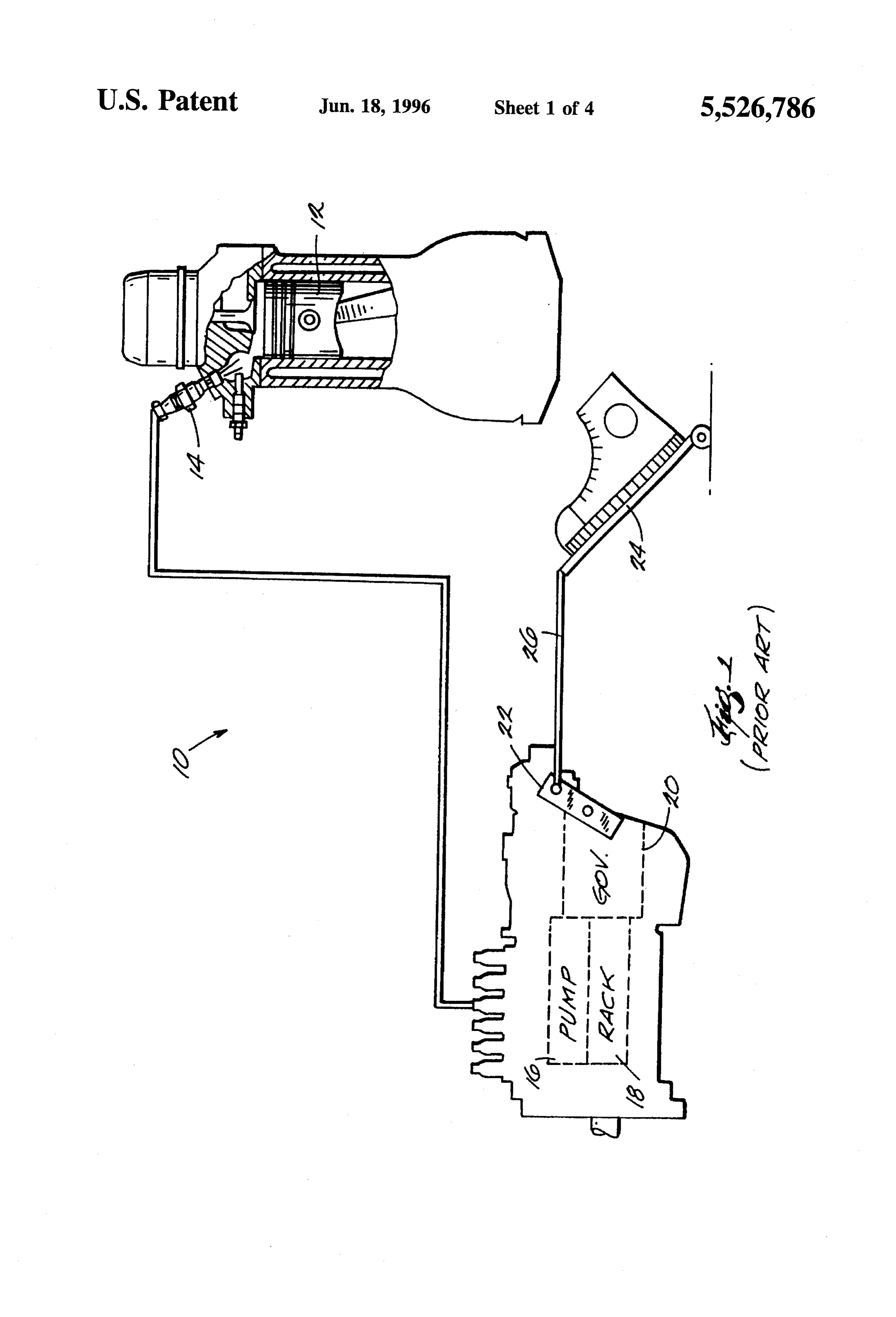
steps include detaching the governor actuating lever from FIG. 3 is a graph illustrating the relationship between the throttle pedal, adding a primary fuel supply system throttle pedal position/governor actuating lever position and which supplies a gaseous fuel to the combustion cylinder, commanded engine speed, and is appropriately labeled and adding an electronically controlled actuator and cou “PRIOR ART";
pling the actuator to the governor actuating lever. The FIG. 4 is a graph representing engine speed versus fuel actuator displaces the governor actuating lever a sufficient delivery quantity for a particular governor actuating lever amount to cause the liquid fuel supply system to supply an position of the engine of FIG. 1, and is appropriately labeled amount of liquid pilot fuel to the combustion cylinder “PRIOR ART";
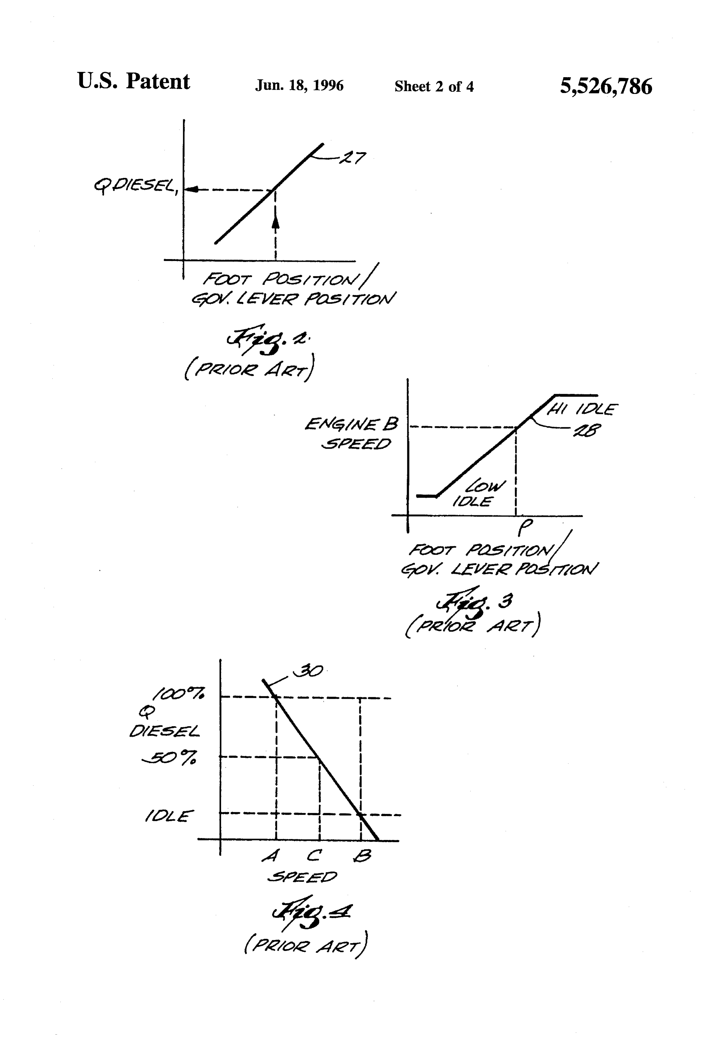
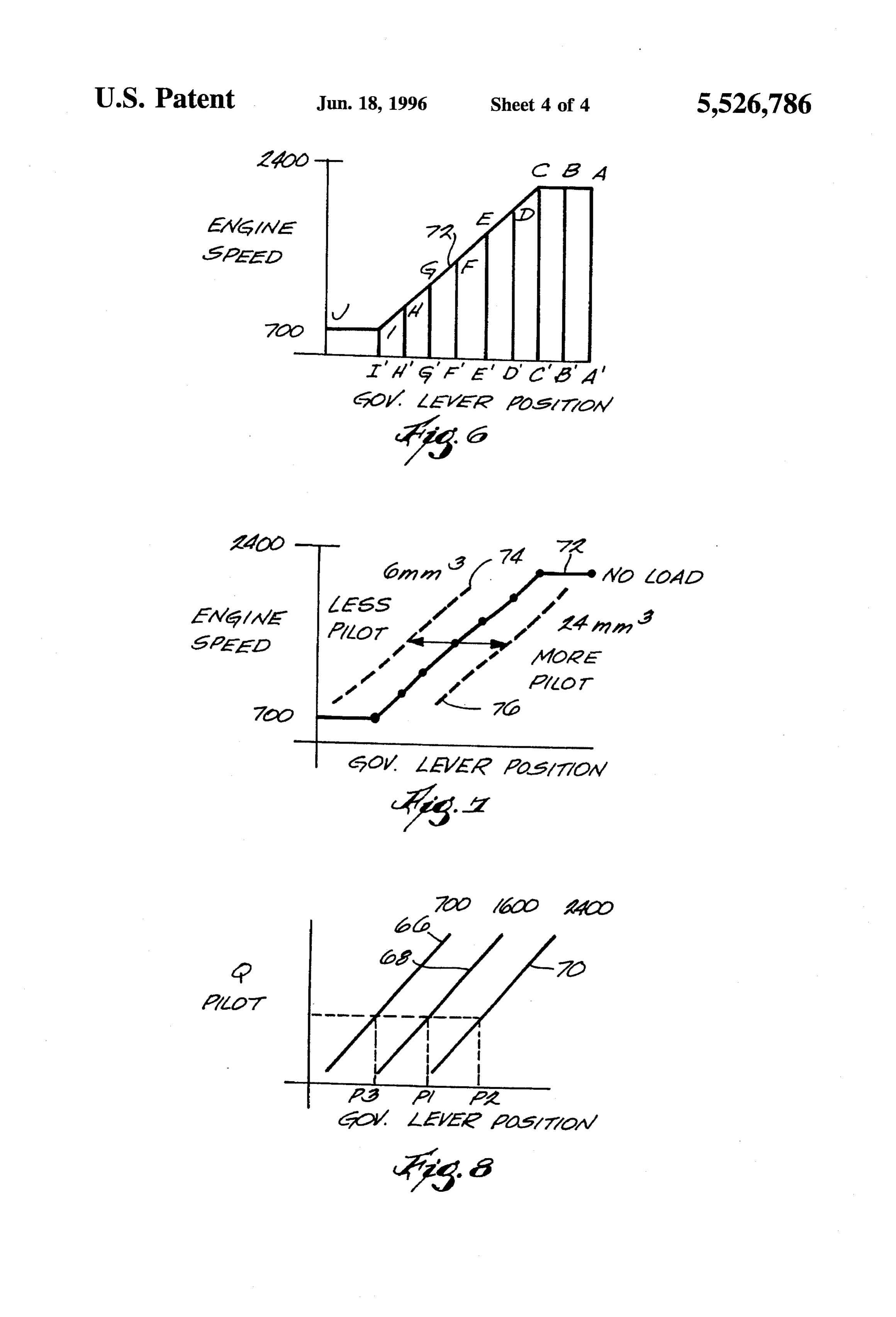
commanded by the controller. FIG. 5 schematically illustrates a dual fuel engine pro Still another object of the invention is to provide a novel O ducible through conversion of the engine of FIG. 1; dual fuel engine. This object is achieved by providing a FIGS. 6 and 7 are graphs of governor actuating lever combustion cylinder, a primary fuel supply system which position versus engine speed and fuel delivery quantity for supplies a gaseous primary fuel to the combustion cylinder, the dual fuel engine of FIG. 5; and a pilot fuel supply system, and an actuator. The pilot fuel FIG. 8 is a graph of governor actuating lever position supply system supplies a liquid pilot fuel to the combustion 15 versus pilot fuel delivery quantity for the engine in FIG. 5.
cylinder and includes a pump, a rack which is connected to the pump and which is movable to vary the fuel delivery quantity per stroke of the pump, and a governor which is DETALED DESCRIPTION OF THE PREFERRED connected to the rack, the governor including an actuating EMBODIMENTS lever which is displaceable to set the position of the rack. 20
The actuator automatically displaces the governor actuating 1. Resume lever to indirectly but effectively control the position of the Pursuant to the invention, a compression ignition engine rack and thus the fuel delivery quantity per stroke of the can be quickly and easily converted into a dual fuel engine pump. simply by adding a gaseous fuel supply system, by discon 25 necting the governor actuating lever from the throttle pedal,
Still another object of the invention is to provide a system for calibrating a pilot liquid fuel supply system of a dual fuel and by adding an electronic controller which controls the internal combustion engine. operation of the gaseous fuel supply system and which sets the governor actuating lever at a position which causes the
In accordance with still another aspect of the invention, this object is achieved by providing means for determining 30 isengine to deliver pilot fuel at a desired quantity. Operation simplified by setting the governor using a droop control governor actuating lever positions at designated liquid fuel technique inherent in governor operation. The system can be delivery quantity per strokes, and means for storing the automatically calibrated to assure the Supply of fuel at a determined positions and the designated liquid fuel delivery precisely controlled quantity per stroke at all engine speeds. quantities per stroke in an electronic memory. The pilot fuel injection system of the resulting engine is Preferably, the system further includes means for sensing 35 non-invasive and permits inherent safety features of the engine speeds under engine operating conditions at which governor to be retained.
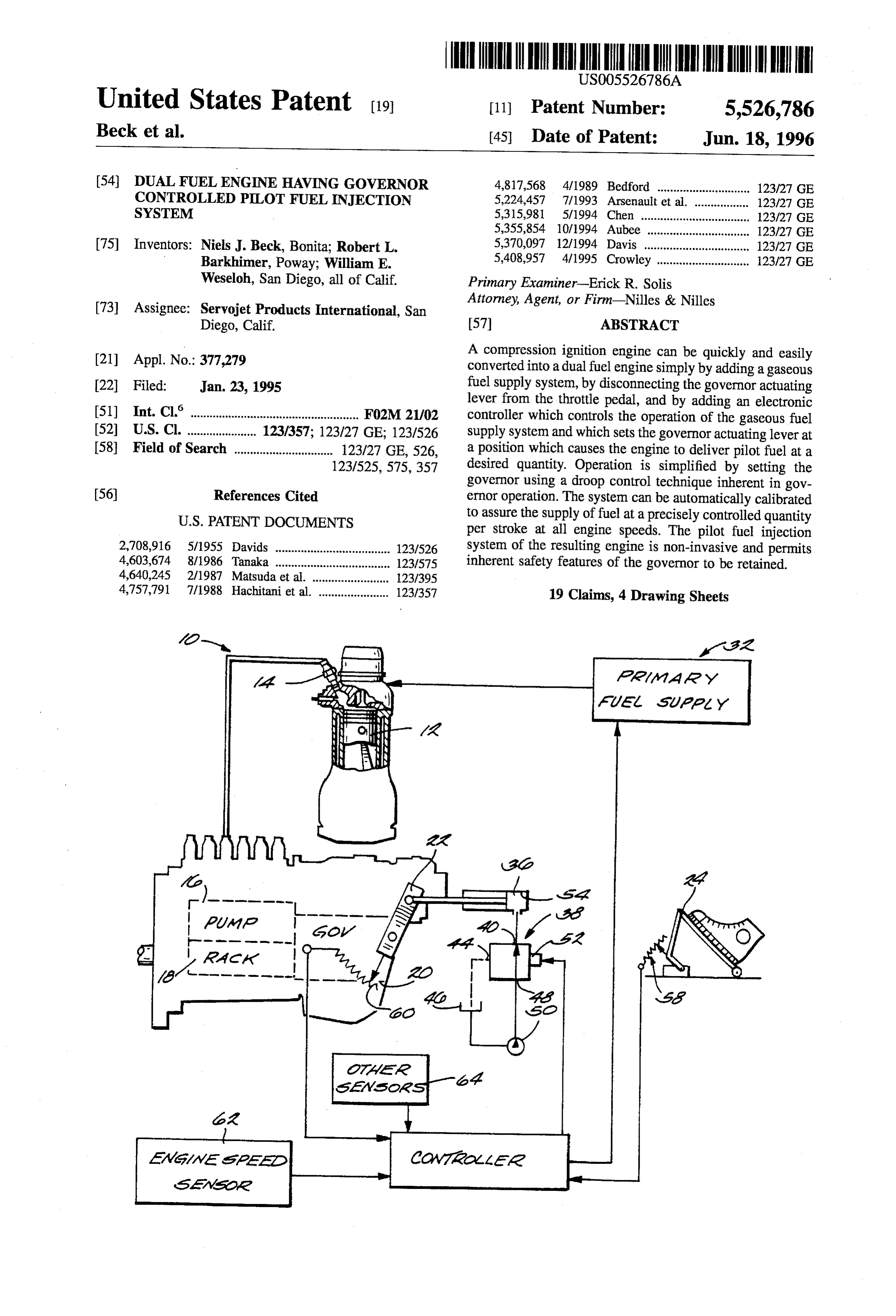
liquid fuel delivery quantities per stroke required to obtain 2. Construction and Operation of Standard Compression said engine speeds are known, and the means for storing Ignition Engine preferably comprises means for creating and storing in said Referring now to FIG. 1, a compression ignition engine memory a table of governor actuating lever position versus 40 10 which is amenable to operation in dual fuel mode fuel delivery quantities per stroke and engine speeds. includes, as is standard in the art, a number of cylinders 12 Also, the converted engine retains the capability for full supplied with diesel or other liquid fuel via a plurality of diesel operation and maintains diesel thermal efficiency. injectors 14 to supply torque to an output shaft (not shown). These and other objects, features and advantages will Fuel is supplied to the injectors 14 by a high pressure pump become apparent to those skilled in the art from the follow 45 which may for example be an in-line piston pump 16. Pump ing detailed description and the accompanying drawings. It 16 delivers fuel at a quantity per stroke determined by an should be understood, however, that the detailed description internal rack 18 the position of which is in turn determined and specific examples, while indicating preferred embodi by the operation of a governor 20. The governor 20 may be ments of the present invention, are given by way of illus either electronically or mechanically controlled and, in the tration and not of limitation. Many changes and modifica 50 illustrated embodiment, is a mechanically controlled gover tions could be made in the scope of the present invention nor having an actuating lever 22 connected to a throttle pedal without departing from the spirit thereof, and the invention 24 by a link 26. In the discussion that follows, "governor includes all such modifications. position' and "governor actuating lever position' will be used interchangeably, it being understood that the former is 55 a direct function of the latter influenced only by engine
BRIEF DESCRIPTION OF THE DRAWINGS speed. The manner in which the governor 20 is responsive A preferred exemplary embodiment of the invention is to the throttle pedal 24 and engine speed to control delivery illustrated in the accompanying drawings in which like of fuel to the engine 10 is well known and will be described only in passing.
reference numerals represent like parts throughout, and in 60 Displacement of the throttle pedal 24 indicates a com which:
mand for an increased engine torque requiring an increase in
FIG. 1 schematically represents a prior art compression fuel as represented by the curve 27 in FIG. 2. Displacement ignition engine, appropriately labeled “PRIOR ART"; of the throttle pedal 24 also commands an engine speed FIG. 2 is a graph illustrating the relationship between which varies with progressive displacement of the throttle throttle pedal position/governor actuating lever position and 65 pedal 24 from low idle to high idle as represented by the torque or fuel delivery quantity per pump stroke, and is curve 28 in FIG. 3. Hence, displacing the throttle pedal 24 appropriately labeled "PRIOR ART"; and thus the governor actuating lever 22 to the position P
Page 8
will command an engine speed B. It is significant to note that CNG injectors emptying into the intake ports of the respec the low idle and high idle speed values are independent of tive cylinders 12 and receiving gas from a common gas throttle pedal position and thus define a safe operating range manifold connected to a conventional source. The gaseous which will not be exceeded by the engine 10 even if the fuel thus supplied could be natural gas, propane, or any other relationship between the throttle pedal 24 and the governor suitable gaseous fuel.
20 is somehow disturbed, e.g., by severing the link 26. The actuator 36 may comprise a pneumatic cylinder, an Conventional mechanical governors operate to control the electric actuator, or any device which displaces the lever 22 pump rack 18 to vary the fuel delivery quantity per stroke or of the governor 20 under action of the controller 34 and fuel delivery quantity per stroke of the pump 16 based upon preferably comprises either a single or a double acting droop. Droop is defined as the percentage difference 10 hydrualic cylinder. In the illustrated embodiment, the actua between commanded engine speed and actual engine speed tor comprises a single acting hydrualic cylinder 36 con in relation to a given throttle pedal and governor settings.
The quantity of fuel required per pump stroke at a designated trolled by a valve 38. The valve 38 is a two position three-way proportional solenoid valve having a control port governor actuating lever position to increase actual engine 40 connected a cylinder end 54 of the cylinder 36, a speed to commanded engine speed increases proportionally 15 discharge port 44 emptying into a tank 46, and a supply port with this droop. Thus, as represented by the curve 30 in FIG. 48 which receives pressurized fluid from the tank 46 via a 4, centrifugal weights or other internal control mechanisms pump 50. A solenoid coil 52 receives electrical current from of the governor 20 control the rack 18 to increase fuel the controller 34 to modulate the valve 38 to set the pressure delivery quantity per stroke from IDLE to 100% of maxi in the cylinder end 54 of cylinder 36 at a designated, variable mum based on the percentage difference between a com 20 level and hence setting the lever 22 a designated position. manded engine speed B and the actual engine speed. If the The controller 34 may comprise any electronic device actual speed is equal to or greater than the commanded speed capable of monitoring engine operation and of controlling B, there is no need to supply additional power to the engine the primary and pilot fuel supply systems and, in the 10, and the governor 20 sets the rack 18 to maintain fuel illustrated embodiment, comprises a programmable digital delivery quantity per stroke at IDLE. However, if the actual 25 microprocessor or electronic control unit (ECU) having a engine speed decreases due to increased load, the amount of RAM, ROM, BUSS, and conventional peripheral devices fuel required to increase engine speed to the commanded preferably including an interface connection for a lap-top speed B increases, and the governor 20 adjusts the rack computer. ECU 34 receives signals indicative of throttle position to increase the amount of fuel delivered per pump position or power command, governor actuating lever posi stroke by an amount equal to the droop or percentage 30 tion, and engine speed from respective sensors 58, 60, and difference between the commanded engine speed B and the 62. ECU 34 also receives signals from additional sensors actual engine speed. Thus, if the droop between the com such as an intake manifold pressure sensor, an air charge manded engine speed B and an actual engine speed C is temperature sensor, and a gaseous fuel composition sensor 50%, the governor 20 will control the rack 18 to deliver fuel (collectively denoted by block 64) and combines these at a rate of 50% of the maximum quantity per pump stroke. 35 signals and the signals from sensors 58, 60 and 62 (1) to set If the droop between the commanded engine speedB and an the desired delivery quantities of primary fuel and pilot fuel actual engine speed A is 100% or greater, the governor 20 based upon instantaneous operating conditions and to (2) will control the rack 18 to deliver fuel at a rate of 100% of control the primary fuel supply system32 and the pilot fuel the maximum quantity per pump stroke. It should be noted supply system accordingly. The manner in which the pri that the curve 30 of FIG. 4 is but one of a family of curves 40 mary fuel supply system 32 is operated and in which the each of which represents droop control at a different constant primary and pilot fuel delivery quantities are commanded governor actuating lever position. are, per se, well known and will not be described in further It has been discovered that the relationship between detail. The manner in which the governor 20 is controlled to commanded speed, governor position, and fuel delivery supply pilot fuel at the commanded quantity per stroke will quantity per pump stroke can be used to automatically 45 now be detailed.
control a governor to deliver a pilot fuel at a desired quantity Referring again to FIG. 4, the diesel fuel delivery quantity per stroke if engine speed is known. A process and system Q supply per pump stroke can be determined at a for effecting such control will now be described. designated governor position and a designated actual engine 3. Construction and Operation of Dual Fuel Engine Having speed. For instance, at a designated governor position rep Governor Controlled Pilot Fuel Injection System 50 resented by the curve 30 and at a designated actual engine Referring to FIG. 5, the engine 10 of FIG. 1 can be speed C, the fuel delivery quantity per stroke is known to be modified to function as a dual fuel engine simply by adding 50% of a known quantity per stroke. It is then a simple a primary fuel supply system 32 (typically comprising a matter to create a map storing pilot fuel quantities at various compressed natural gas or CNG supply system) and a governor actuating lever positions and engine speeds as corresponding controller 34 and by controlling the governor 55 illustrated by the family of curves 66, 68 and 70 in FIG. 8, 20 by the controller 34 rather than by the throttle pedal 24 and to set the governor actuating lever position to control the so that the diesel or other liquid fuel supply system functions rack 18 and the pump 16 to supply a commanded pilot fuel as a pilot fuel supply system. The engine 10 remains quantity per stroke. Thus, assuming that the engine speed as essentially unchanged and includes the cylinders 12, the detected by sensor 62 is 1,600 RPM, and assuming that the injectors 14, the output shaft, the pump 16 including the rack 60 quantity of pilot fuel per stroke commanded by the control 18, and the governor 20. The engine 10 is modified only by lier is at a level Q1, the controller 34 can use the curve 68 to replacing the mechanical link 26 of FIG. 1 with an actuator determine the governor actuating lever position P1 required 36, by adding the primary fuel supply system 32, and by to supply the desired amount of fuel Q1 per stroke at the adding the controller 34 and associated sensors. sensed actual engine speed. Controller or ECU 34 then The primary fuel supply system 32 could supply gaseous 65 displaces the governor actuating lever 22 accordingly using fuel to the engine manifold via a single metering valve but the actuator 36 and feedback from the sensor 60. FIG. 8 also preferably comprises a plurality of electronically controlled illustrates that different governor actuating lever positions
Page 9
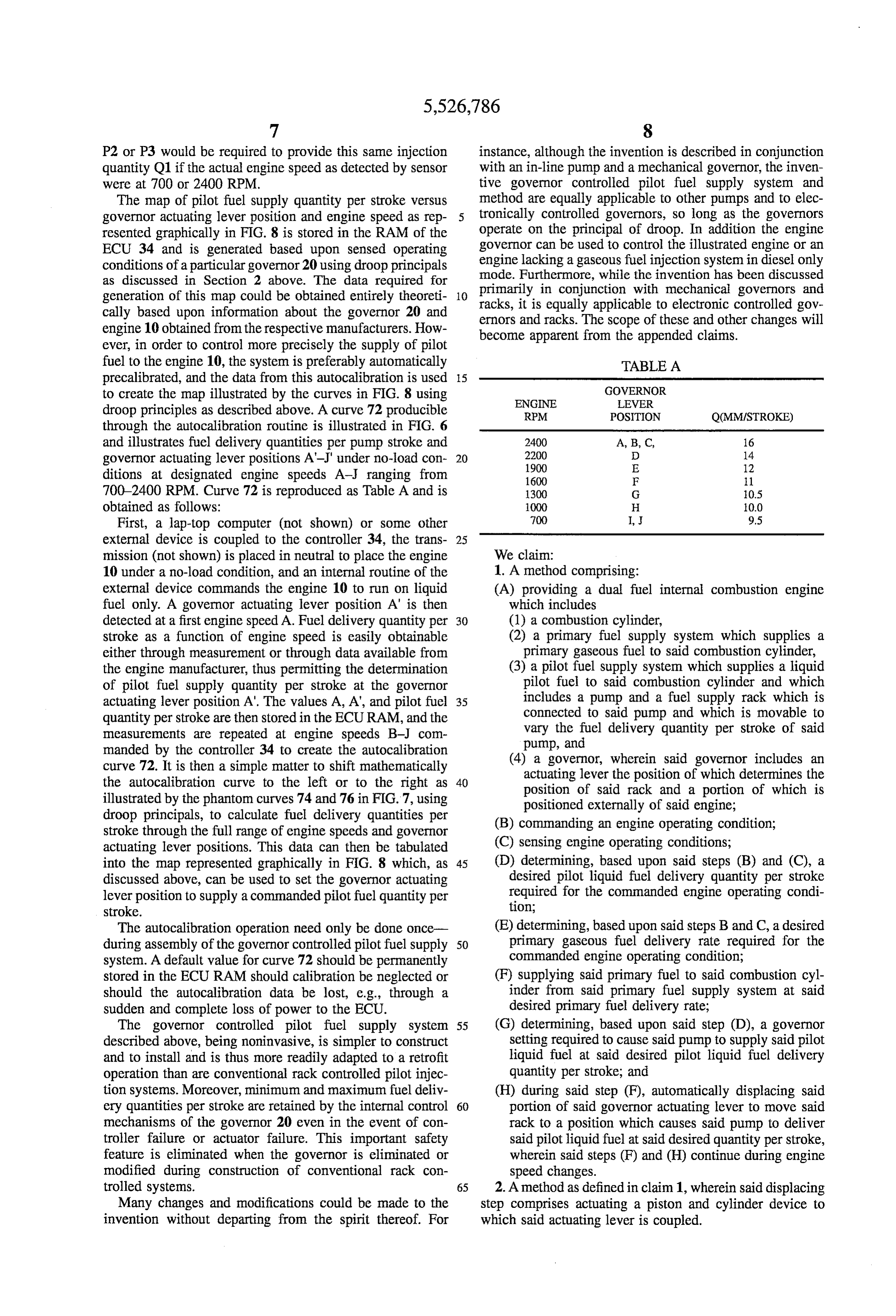
P2 or P3 would be required to provide this same injection instance, although the invention is described in conjunction quantity Q1 if the actual engine speed as detected by sensor with an in-line pump and a mechanical governor, the inven were at 700 or 2400 RPM. tive governor controlled pilot fuel supply system and The map of pilot fuel supply quantity per stroke versus method are equally applicable to other pumps and to elec governor actuating lever position and engine speed as rep tronically controlled governors, so long as the governors resented graphically in FIG. 8 is stored in the RAM of the operate on the principal of droop. In addition the engine ECU 34 and is generated based upon sensed operating governor can be used to control the illustrated engine or an conditions of a particular governor 20 using droop principals engine lacking a gaseous fuel injection system in diesel only as discussed in Section 2 above. The data required for mode. Furthermore, while the invention has been discussed generation of this map could be obtained entirely theoreti 10 primarily racks, it is in conjunction with mechanical governors and equally applicable to electronic controlled gov cally based upon information about the governor 20 and ernors and racks. The scope of these and other changes will engine 10 obtained from the respective manufacturers. How become apparent from the appended claims. ever, in order to control more precisely the supply of pilot fuel to the engine 10, the system is preferably automatically TABLE A precalibrated, and the data from this autocalibration is used 5 to create the map illustrated by the curves in FIG. 8 using GOVERNOR
droop principles as described above. A curve 72 producible RPM POSITION Q(MMISTROKE) through the autocalibration routine is illustrated in FIG. 6 and illustrates fuel delivery quantities per pump stroke and 2400 A, B, C, 16 governor actuating lever positions A-J" under no-load con 20 2200
ditions at designated engine speeds A- ranging from 1600 F 1. 700–2400 RPM. Curve 72 is reproduced as Table A and is 1300 G 10.5 obtained as follows: 1000 H 0.0 First, a lap-top computer (not shown) or some other 700 I, 9.5 external device is coupled to the controller 34, the trans 25 mission (not shown) is placed in neutral to place the engine We claim:
10 under a no-load condition, and an internal routine of the 1. A method comprising:
external device commands the engine 10 to run on liquid (A) providing a dual fuel internal combustion engine fuel only. A governor actuating lever position A' is then which includes detected at a first engine speed A. Fuel delivery quantity per 30 (1) a combustion cylinder, stroke as a function of engine speed is easily obtainable (2) a primary fuel supply system which supplies a either through measurement or through data available from primary gaseous fuel to said combustion cylinder, the engine manufacturer, thus permitting the determination (3) a pilot fuel supply system which supplies a liquid of pilot fuel supply quantity per stroke at the governor pilot fuel to said combustion cylinder and which actuating lever position A'. The values A, A, and pilot fuel 35 includes a pump and a fuel supply rack which is quantity per stroke are then stored in the ECURAM, and the connected to said pump and which is movable to measurements are repeated at engine speeds B-J com vary the fuel delivery quantity per stroke of said manded by the controller 34 to create the autocalibration pump, and curve 72. It is then a simple matter to shift mathematically (4) a governor, wherein said governor includes an the autocalibration curve to the left or to the right as 40 actuating lever the position of which determines the illustrated by the phantom curves 74 and 76 in FIG.7, using position of said rack and a portion of which is droop principals, to calculate fuel delivery quantities per positioned externally of said engine; stroke through the full range of engine speeds and governor (B) commanding an engine operating condition; actuating lever positions. This data can then be tabulated (C) sensing engine operating conditions; into the map represented graphically in FIG. 8 which, as 45 (D) determining, based upon said steps (B) and (C), a discussed above, can be used to set the governor actuating desired pilot liquid fuel delivery quantity per stroke lever position to supply a commanded pilot fuel quantity per required for the commanded engine operating condi stroke. tion;
The autocalibration operation need only be done once (E) determining, based upon said steps B and C, a desired during assembly of the governor controlled pilot fuel supply 50 primary gaseous fuel delivery rate required for the system. A default value for curve 72 should be permanently commanded engine operating condition; stored in the ECU RAM should calibration be neglected or (F) supplying said primary fuel to said combustion cyl should the autocalibration data be lost, e.g., through a inder from said primary fuel supply system at said sudden and complete loss of power to the ECU. desired primary fuel delivery rate; The governor controlled pilot fuel supply system 55 (G) determining, based upon said step (D), a governor described above, being noninvasive, is simpler to construct setting required to cause said pump to supply said pilot and to install and is thus more readily adapted to a retrofit liquid fuel at said desired pilot liquid fuel delivery operation than are conventional rack controlled pilot injec quantity per stroke; and tion systems. Moreover, minimum and maximum fuel deliv (H) during said step (F), automatically displacing said ery quantities per stroke are retained by the internal control 60 portion of said governor actuating lever to move said mechanisms of the governor 20 even in the event of con rack to a position which causes said pump to deliver troller failure or actuator failure. This important safety said pilot liquid fuel at said desired quantity per stroke, feature is eliminated when the governor is eliminated or wherein said steps (F) and (H) continue during engine modified during construction of conventional rack con speed changes.
trolled systems. 65 2. A method as defined in claim 1, wherein said displacing Many changes and modifications could be made to the step comprises actuating a piston and cylinder device to invention without departing from the spirit thereof. For which said actuating lever is coupled.
Page 10
3. A method as defined in claim 1, wherein said deter (4) a governor which includes and actuating lever the mining step comprises sensing a throttle pedal position and position of which determines the position of said engine speed. rack and a portion of which is positioned externally 4. A method as defined in claim 3, further comprising of said engine, said governor being of a type which sensing a governor actuating lever position. is designed to use a principle of governor droop to 5. A method as defined in claim 1, further comprising said said rack at a position required to cause an actual calibrating said system by determining governor actuating engine speed to approach a commanded engine lever positions providing designated pilot liquid fuel deliv speed;
ery quantities per stroke under designated engine operating conditions. 10
(B) commanding an engine operating condition;
6. A method as defined in claim 5, wherein said calibrating (C) electronically determining a pilot liquid fuel delivery step further comprises quantity per stroke required for the commanded engine (1) sensing engine speeds under engine operating condi operating condition; and tions at which liquid fuel delivery quantities per stroke (D) determining, based upon said step B, a desired required to obtain said engine speeds are known, 15 primary fuel delivery rate required for the commanded (2) sensing governor actuating lever positions at each of engine operating condition;
the sensed engine speeds, and (E) supplying said primary gaseous fuel to said combus (3) creating and storing a table of governor actuating lever tion cylinder from said primary fuel supply system at position versus engine speed and liquid fuel delivery 20 said desired primary fuel delivery rate; quantity per stroke. (F) automatically and electronically controlling an actua 7. A method as defined in claim 1, wherein said step of tor, coupled to said portion of said governor actuating commanding an engine operating condition comprises dis lever, to displace said governor actuating lever to move placing a throttle pedal to command an engine speed. said rack to a position which causes said pump to 8. A method comprising: deliver said pilot liquid fuel at said desired quantity per (A) determining a desired pilot liquid fuel delivery quan 25 stroke, wherein said steps (E) and (F) continue during tity per stroke required for a commanded engine oper engine speed changes.
ating condition for a dual fuel engine, said engine being 11. A method of converting an internal combustion engine fueled primarily by a gaseous fuel; and then from single fuel mode to dual fuel mode, said method comprising
(B) automatically controlling a governor of said engine to 30 cause a pump of said engine to deliver said liquid fuel (A) providing an engine which is operable in single fuel mode and which includes at said desired quantity per stroke, wherein said gov (1) a combustion cylinder, ernor is a type which is designed to use a principle of (2) a liquid fuel supply system which supplies liquid governor droop to set said pump at a position required to cause an actual engine speed to approach a com 35 fuel to said combustion cylinder and which includes manded engine speed, wherein said step (B) is per a fuel pump, a fuel supply rack which is connected formed while said gaseous fuel is being supplied to said to said pump and which is movable to vary the fuel engine, and wherein said gaseous fuel and said pilot delivery quantity per stroke of said pump, and a liquid fuel continue to be supplied to said engine during governor which sets the position of said rack, said engine speed changes. 40 governor including an actuating lever the position of 9. A method of calibrating a pilot liquid fuel supply which determines the position of said rack and a system of a dual fuel internal combustion engine, compris portion of which is positioned externally of said ing sensing governor actuating lever positions at designated engine, said governor being of a type which is liquid fuel delivery quantities per stroke and storing the designed to use a principle of governor droop to set sensed positions in an electronic memory, wherein said 45 the position of said rack at a position required to calibrating step further comprises cause an actual engine speed to approach a com (1) sensing engine speeds under engine operating con manded engine speed; and ditions at which liquid fuel delivery quantities per (3) a throttle pedal which is mechanically coupled to stroke required to obtain said engine speeds are said governor actuating lever,
(B) detaching said governor actuating lever from said (2) sensing governor actuating lever positions at each throttle pedal;
of the sensed engine speeds, and (C) adding a primary fuel supply system which supplies (3) creating and storing in said memory a table of a primary gaseous fuel to said combustion cylinder; governor actuating lever position verse liquid fuel (D) adding an electronically controlled actuator and cou delivery quantity per stroke and engine speed. 55 pling said actuator to said portion of said governor 10. A method comprising: actuating lever, and
(A) providing an internal combustion engine which (E) adding a electronic controller which is coupled to said includes primary fuel supply system and to said actuator, said (1) a combustion cylinder; controller controlling said actuator to displace said (2) a pilot fuel supply which supplies a liquid fuel to 60 governor actuating lever a sufficient amount to cause said combustion cylinder and which includes a pump said liquid fuel supply system to supply an amount of and fuel supply rack which is connected to said liquid pilot fuel to said combustion cylinder com pump and which is movable to vary the fuel delivery manded by said controller, said controller controlling quantity per stroke of said pump, said actuator and said primary fuel supply system to (3) a primary fuel supply system which supplies a 65 continue to supply both said primary gaseous fuel and primary gaseous fuel to said combustion cylinder, said liquid pilot fuel to said cylinder during engine and speed changes.
Page 11
12. A method as defined in claim 11, further comprising said primary fuel supply system to continue to supply automatically calibrating said system following said step D both said primary gaseous fuel and said pilot liquid fuel based upon sensed operating characteristics of said gover to said cylinder during engine speed changes. O. 15. An engine as defined in claim 14, wherein said 13. A method of converting an internal combustion engine actuator comprises a piston and cylinder device. from single fuel mode to dual fuel mode, said method 16. An engine as defined in claim 15, wherein said piston comprising and cylinder device is a hydrualic piston and cylinder (A) providing an engine which is operable in single fuel device, and further comprising a valve supplying pressur mode and which includes ized liquid to at least one side of the piston of said hydraulic piston and cylinder device.
(1) a combustion cylinder, 10 17. An engine as defined in claim 14, further comprising (2) a liquid fuel supply system which supplies liquid (A) a throttle pedal position sensor; fuel to said combustion cylinder and which includes (B) a governor actuating lever position sensor; a fuel pump, an electronically controlled fuel supply rack which is connected to said pump and which is 15 (C) (1) an engine speed sensor, and electronically movable to vary the fuel delivery (D) a foot pedal position sensor, wherein said electronic quantity per stroke of said pump, and an electroni control unit is coupled to said actuator, said foot pedal cally controlled governor which sets the position of position sensor, said governor actuating lever position said rack to cause said pump to deliver fuel at a sensor, and said engine speed sensor. commanded quantity per stroke, said governor 18. A system for calibrating a pilot liquid fuel supply including an actuating lever a portion of which is 20 system of a dual fuel internal combustion engine, compris positioned externally of said engine and the position ing of which determines the position of said rack; and (A) means for determining governor actuating lever posi (3) a throttle pedal which is mechanically coupled to tions at designated liquid fuel delivery quantities per said governor actuating lever, stroke;
(B) detaching said governor actuating lever from said 25 (B) means for storing the determining positions and the throttle pedal; designated liquid fuel delivery quantities per stroke in (C) adding a primary fuel supply system which supplies an electronic memory; and a primary gaseous fuel to said combustion cylinder; (C) means for sensing engine speeds under engine oper (D) adding an electronically controlled actuator and cou 30 ating conditions at which liquid fuel delivery quantities pling said actuator to said portion of said governor per stroke required to obtain said engine speeds are actuating lever; and known, and wherein said means for storing comprises (E) adding an electronic controller which is coupled to means for creating and storing in said memory a table said primary fuel supply system and to said actuator, of governor actuating lever position verse fuel delivery said controller controlling said actuator to displace said 35 quantities per stroke and engine speeds. governor actuating lever a sufficient amount to cause 19. A method comprising:
said liquid fuel supply system to supply an amount of (A) providing an internal combustion engine which liquid pilot fuel to said combustion cylinder com includes manded by said controller, said controller controlling (1) a combustion cylinder, said actuator and said primary fuel supply system to 40 (2) a pilot fuel supply system which supplies a pilot continue to supply both said primary gaseous fuel and liquid fuel to said combustion cylinder and which said pilot liquid fuel to said cylinder during engine includes a pump and a fuel supply rack which is speed changes. connected to said pump and which is movable to 14. A dual fuel engine comprising: vary the fuel delivery quantity per stroke of said (A) a combustion cylinder; 45 pump,
(B) a primary fuel supply system which supplies a gas (3) a primary fuel supply system which supplies a eous primary fuel to said combustion cylinder; primary gaseous fuel to said combustion cylinder, (C) a pilot fuel supply system which supplies a liquid pilot (4) a mechanical governor which mechanically sets the fuel to said combustion cylinder and which includes 50 position of said rack, said governor a) having a (1) a pump, governor actuating lever the position of which deter (2) a rack which is connected to said pump and which mines the position of said rack and a portion of is movable to vary the fuel delivery quantity per which is positioned externally of said engine b) stroke of said pump, and being of a type which is designed to use a principle (3) a governor which is connected to said rack, said 55 of governor droop to set said rack at a position governor including an actuating lever which is dis required to cause an actual engine speed to approach placeable to set the position of said rack and a a commanded engine speed, portion of which is positioned externally of said (5) an actuator coupled to said portion of said governor engine; actuating lever, (6) a throttle pedal,
(D) an actuator which is coupled to said portion of said 60 (7) a throttle pedal position sensor coupled to said actuating lever, and throttle pedal,
(E) an electric controller which is coupled to said primary (8) an engine speed sensor, fuel supply system and to said actuator, said controller (9) a governor actuating lever position sensor, and causing said actuator to automatically displace said (10) an electronic controller coupled to said primary governor actuating lever to control the position of said 65 fuel supply system, said actuator, said throttle pedal rack and thus the fuel delivery quantity per stroke of position sensor, said governor actuating lever posi Saidpump, said controller controlling said actuator and tion sensor, and said engine speed sensor;
Page 12
(B) commanding an engine operating speed using said to a position which causes said pump to deliver said throttle pedal sensor; pilot liquid fuel at said desired quantity per stroke, (C) sensing engine operating conditions, (G) automatically and electronically controlling said pri (D) electronically determining, based on said steps (B) 5 mary fuel supply system to supply said primary gas and (C), a desired primary gaseous fuel delivery rate required for the commanded engine operating speed; eous fuel to said combustion cylinder at said desired (E) electronically determining, based on said steps (B) primary gaseous fuel delivery rate; and (C), a pilot liquid fuel delivery quantity per stroke (H) automatically and electronically controlling said required for the commanded engine operating condi 10 actuator to displace said governor actuating lever into tion; said required setting, wherein said steps (G) and (H) (F) determining, based upon a prevailing sensed engine continue during engine speed changes. speed and upon a principle of governor droop, a gov ernor actuating lever setting required to move said rack ck k cit k cK
Provenance
- Collection
- Cited prior art
- Original PDF
- patentimages.storage.googleapis.com →
- Filed
- 1995-01-23
- Pages
- 12
- Method
- pdftotext (the PDF's own text layer) + pdftoppm 300dpi page scans
- Source
- Google Patents bibliographic record
- Granted
- 1996-06-18
- Inventors
- Niels J. Beck; Robert L. Barkhimer; William E. Weseloh; Servojet Products International
- Transcribed from
- patentimages.storage.googleapis.com →