patent · US6177761B1
LED with light extractor
23 January 2001
Page 1 — bibliographic record
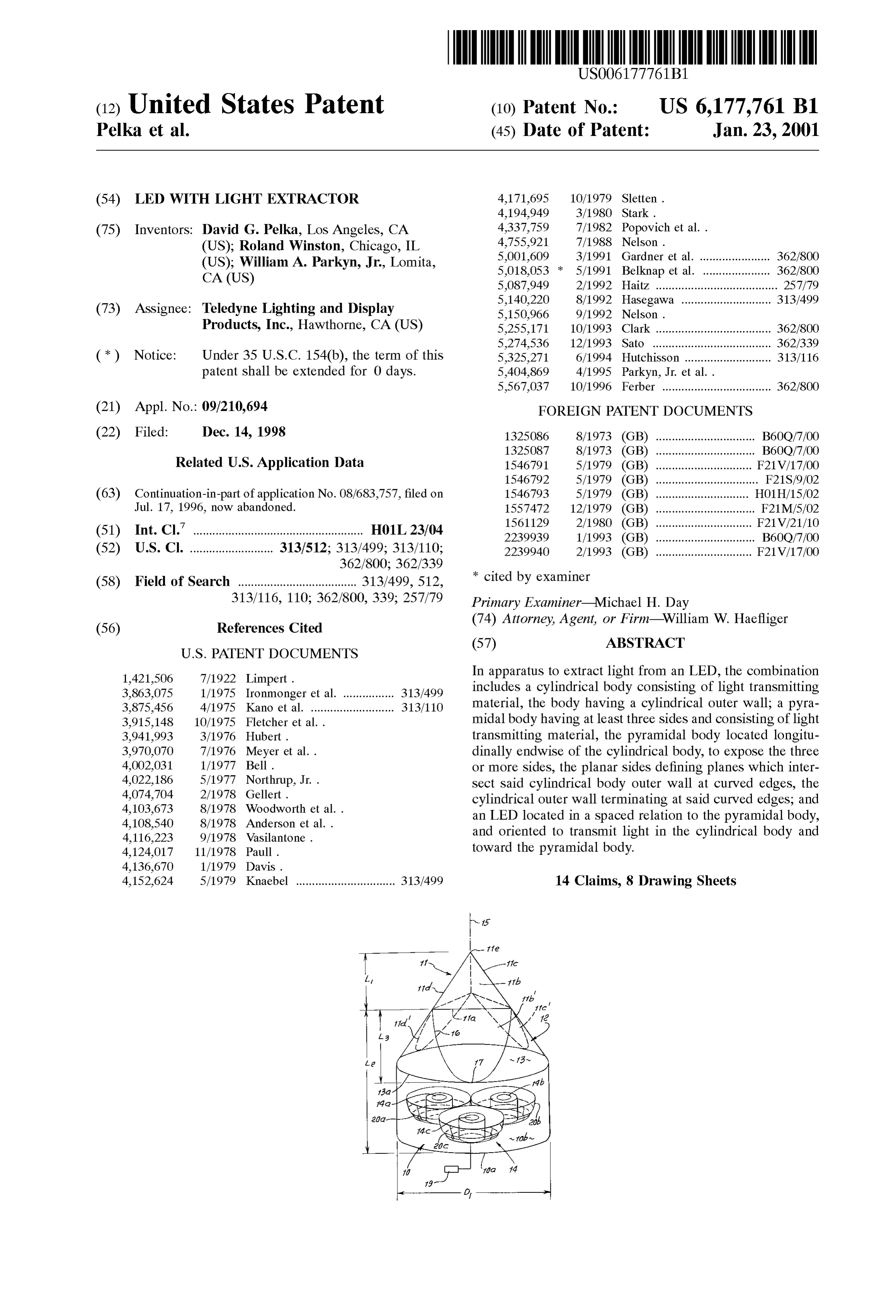
(12) United States Patent (10) Patent No.: US 6, 177,761 B1 Pelka et al. (45) Date of Patent: Jan. 23, 2001
(54) LED WITH LIGHT EXTRACTOR 4,171,695 10/1979 Sletten.
(75) Inventors: David G. Pelka, Los Angeles, CA 4,337,759 7/1982 Popovich et al. . (US); Roland Winston, Chicago, IL
1. Nels et al
Sylam A. Parkyn, Jr., Lomita, 5,018,053 * 5/1991 Belknap et al. ..................... 362/800 5,087,949 2/1992 Haitz ...................................... 257/79
O O 5,140.220 8/1992 Hasegawa ............................ 313/499 (73) Assignee: Teledyne Lighting and Display 5.150,966 8: wa f Products, Inc., Hawthorne, CA (US) 5,255,171 10/1993 Clark .................................... 362/800 5,274,536 12/1993 Sato ......... ... 362/339 (*) Notice: Under 35 U.S.C. 154(b), the term of this 5,325,271 6/1994 Hutchisson ........................... 313/116 patent shall be extended for 0 days. 5,404,869 4/1995 Parkyn, Jr. et al..
5,567,037 10/1996 Ferber .................................. 362/800 (21) Appl. No.: 09/210,694 FOREIGN PATENT DOCUMENTS (22) Filed: Dec. 14, 1998 1325086 8/1973 (GB) ............................... B60O/7/OO O O 1325087 8/1973 (GB) ... ... B600/7/OO Related U.S. Application Data 1546791 5/1979 (GB) ... ... F21 V/17/OO 1546792 5/1979 (GB) ................................ F21S/9/02 (63) Continuation-in-part of application No. 08/683,757, filed on 1546793 5/1979 (GB) ... ... HO1H/15/02 Jul. 17, 1996, now abandoned. 1557472 12/1979 (GB) ... ... F21M/5/02 1561129 2/1980 (GB) ... ... F21V/21/10 (51) Int. Cl." ................................................. H01L23/04 2239939 1. /1993 (GB) ... ... B600/7/OO (52) U.S. Cl. .......................... 313/512; 313/499; 313/110; 2239940 2/1993 (GB) .............................. F21 V/17/OO
(58) Field of Search ..................................... 313/499, 512, cited by examiner 313/116, 110; 362/800, 339; 257/79 Primary Examiner Michael H. Day (56) References Cited (74) Attorney, Agent, or Firm William W. Haefliger
In apparatus to extract light from an LED, the combination 3. A: Age, et al 313/499 includes a cylindrical body consisting of light transmitting
10/1975 Fletcher et al..
material, the body having a cylindrical outer wall; a pyra midal body having at least three Sides and consisting of light 3,941,993 3/1976 Hubert. transmitting material, the pyramidal body located longitu 3,970,070 7/1976 Meyer et al.. dinally endwise of the cylindrical body, to expose the three 4,002,031 1/1977 Bell. or more Sides, the planar Sides defining planes which inter 4,022,186 5/1977 Northrup, Jr. . Sect Said cylindrical body outer wall at curved edges, the E. s2. WI orth et al cylindrical Outer wall terminating at Said curved edges, and 4.108.540 s: 978 With an LED located in a Spaced relation to the pyramidal body, 4,116.223 9/1978 Vasilantone and oriented to transmit light in the cylindrical body and 4,124,017 11/1978 Paul. toward the pyramidal body.
4,152,624 5/1979 Knaebel ............................... 313/499 14 Claims, 8 Drawing Sheets
Page 2
Drawing sheet — no readable text.
Page 3
Drawing sheet — no readable text.
Page 4
Drawing sheet — no readable text.
Page 5
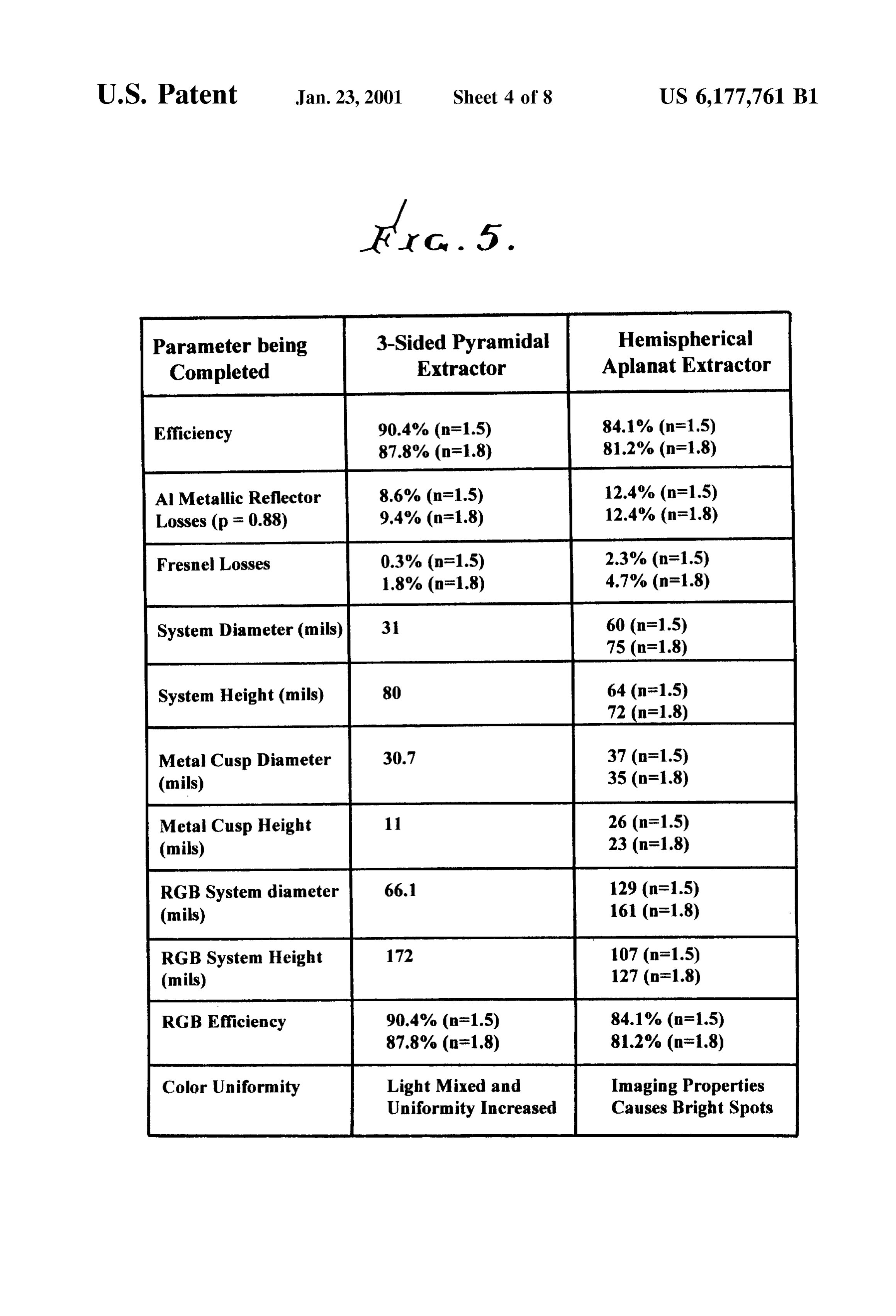
Parameter being 3-Sided Pyramidal Hemispherical Completed Extractor Aplanat Extractor
Efficiency 90.4% (n=1.5) 84.1% (n=1.5)
Al Metallie Reflector 8.6% (n=1.5) 12.4% (n=1.5) Losses (p = 0.88) 9.4% (n=1.8) 12.4% (n=1.8) Fresnel Losses 0.3% (n=1.5) 2.3% (n=1.5)
System Diameter (mils) 31 60 (n=1.5)
System Height (mils) 64 (n=1.5)
Metal Cusp Diameter 30.7 37 (n=1.5) (mils) 35 (n=1.8) Metal Cusp Height 26 (n=1.5) (mils) 23 (n=1.8) RGB System diameter 129 (n=1.5) (mils) 161 (n=1.8) RGB System Height 172 107 (n=1.5) (mils) 127 (n=1.8) RGB Efficiency 90.4% (n=1.5) 84.1% (n=1.5)
Color Uniformity Light Mixed and Imaging Properties Uniformity Increased Causes Bright Spots
Page 6
Drawing sheet — no readable text.
Page 7
Drawing sheet — no readable text.
Page 8
Drawing sheet — no readable text.
Page 9
Drawing sheet — no readable text.
Page 10
LED WITH LIGHT EXTRACTOR 3-Sided pyramidal Structure is a preferred configuration, one with more than 3 sides is also effective. Additionally, an
This application is a continuation-in-part application of RGB (red, green, blue) extractor System that varies its color prior U.S. patent application Ser. No. 08/683,757, filed Jul. balance can be made very compactly. Three LEDs, each 17, 1996, now abandoned. emitting at a specific wavelength or color, can be combined This invention concerns efficient extraction of light from into one extractor System that can change color output by Solid transparent media, and more particularly by the use of independently varying the emission of each LED. In this pyramidal Structure. regard, the aplanat System of prior art requires a System Light produced inside a high index of refraction material diameter at least twice the diameter of the pyramidal extrac may be trapped by total internal reflection. This is particu tor. Also, the present pyramidal System design is indepen larly true in a geometry of high Symmetry, Say a cube or dent of the index of refraction within the extractor. parallelepiped. This poses a problem for light emitting A further object of the invention is to provide an improved diodes (LED's) where the index of refraction is very high, apparatus to extract light from multiple LEDS. The apparatus i.e. greater than three, So that only a Small fraction of the comprises:
light emerges. There is need for a means to enable a very 15 a) a transparent body having a first region in which the large fraction of the light to emerge from LED associated LEDs are at least partly received, transmission media, in order to significantly increase the b) the body having a second region in the paths of light efficiency of light transmission from LEDs. transmission from the LEDs, and acting to mix Such Various means have been Suggested or actually used, to light transmission, extract light by geometric means, but these are not particu c) the body having a third region in the path of light larly efficient. For example: transmission from the Second region, the third region a) The LED can be embedded in a sphere of the same high being of reduced volume from which mixed light is index material. This is possible only for a point Source transmitted, at the emitter center and not for a finite size emitter. In addition, emerging light has large Fresnel reflection at 25 d) the Second region having cylindrical Surface shape between Surface areas which are continuations of the interface, (n-1)/(n+1) which is s25% for n=3. planes defined by Sides of Said third pyramid region. b) An aplanatic lens, which is a hemisphere of radius r AS referred to above, the third region may preferably have with conjugates at r/n and nr., has been used to collimate pyramidal shape, the Second region may have conical shape, the light within the Brewster Angle in an attempt to and the first region may have cylindrical shape. In this reduce Fresnel reflections. Typically, the material has regard, the Second region typically has Surfaces that are index ns 1.5, so that much of the light, i.e. over 16%, continuations of planes defined by the sides of the third remains trapped in the aplanatic lens, because of its pyramid region. Three LED’s may be employed, in a cluster, high (rotational) symmetry. By keeping all reflections and may, for example, respectively be red, green and blue at angles inside the Brewster's Angle, losses are rela light emitting, and there may be means for controlling the tively Small, but the tradeoff is a much greater System 35 relative emissions from the LEDs, for color control of the size than the actual LED. mixed light transmitted from the third region. SUMMARY OF THE INVENTION These and other objects and advantages of the invention, as well as the details of an illustrative embodiment, will be
It is a major object of the invention to provide an 40 more fully understood from the following Specification and improved LED light extraction means embodying a pyra drawings, in which:
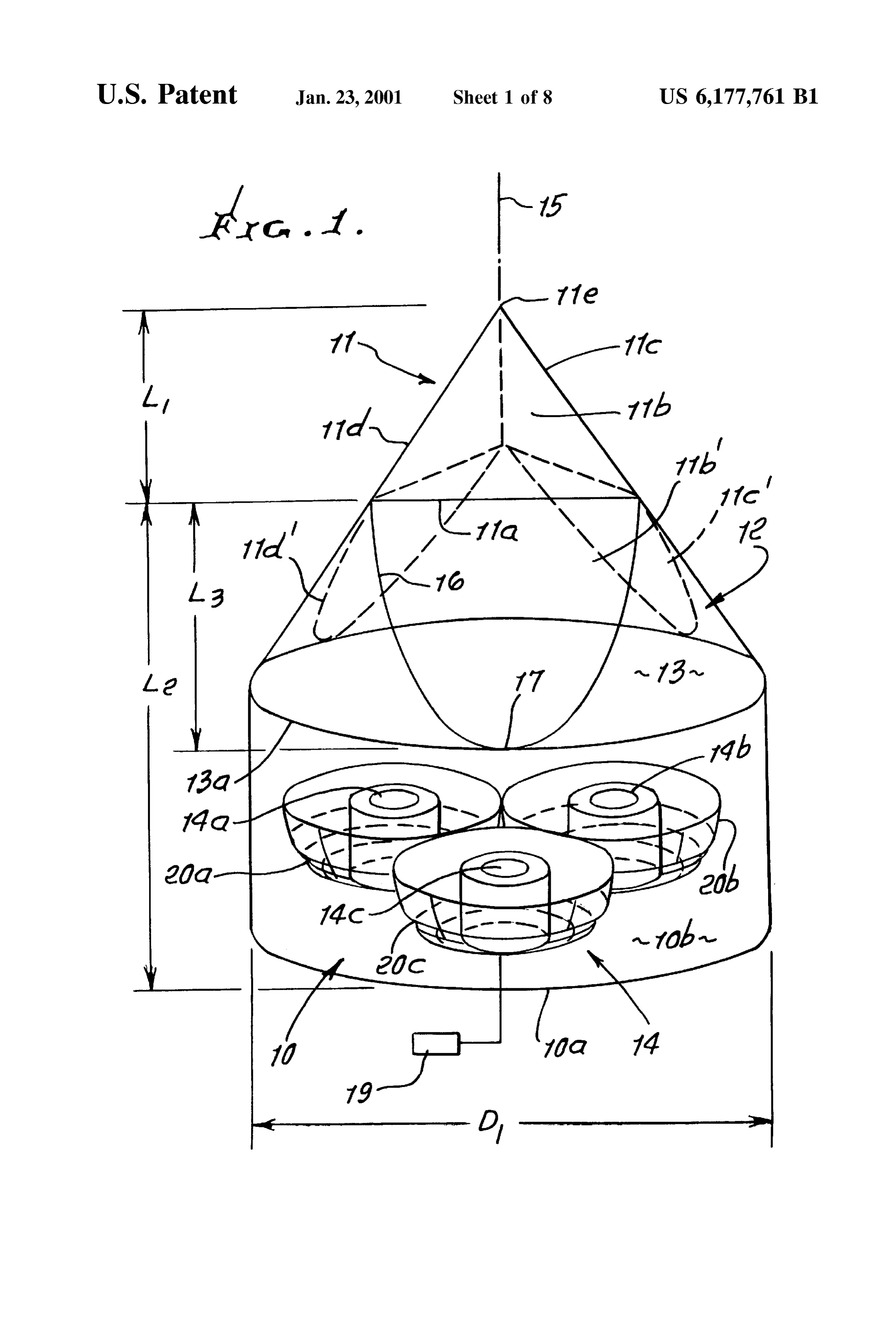
midal configuration. Basically, the extraction means com prises: DRAWING DESCRIPTION a) a cylindrical body consisting of light transmitting FIG. 1 is a perspective view of a pyramidal light extractor material, the body having a cylindrical Outer wall, 45 incorporating the invention;
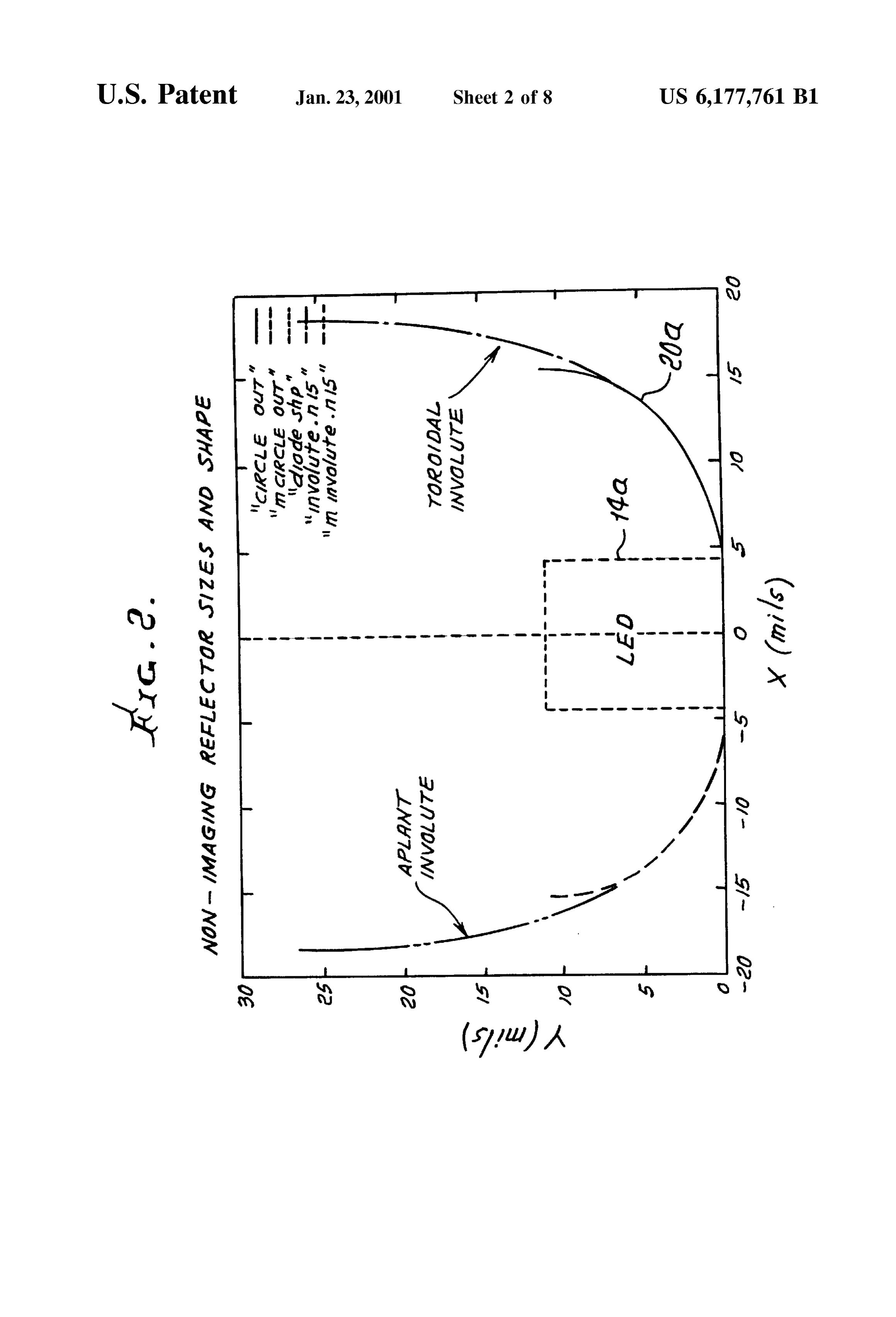
b) a pyramidal body having at least three planar Sides and FIG. 2 is a graph;
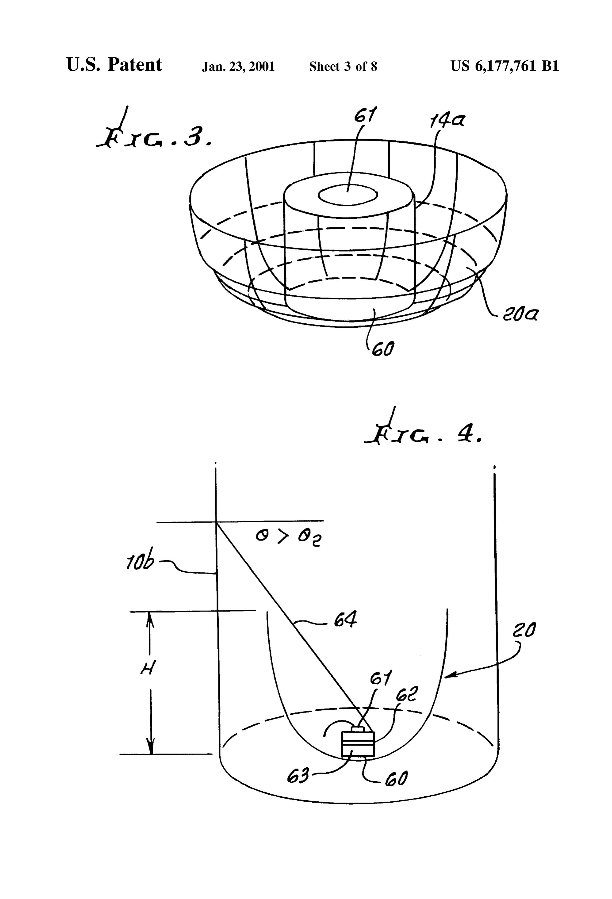
consisting of light transmitting material, the pyramidal FIG. 3 is a perspective view of an LED mounted within body located longitudinally endwise of the cylindrical a reflector;
body, to expose the three or more sides, the planar Sides defining planes which interSect the cylindrical body 50 FIG. 4 is a section taken in elevation through the FIG. 3 outer wall at curved edges, the cylindrical outer wall reflector and showing the centered LED;
terminating at Such curved edges, FIG. 5 is a tabulation;
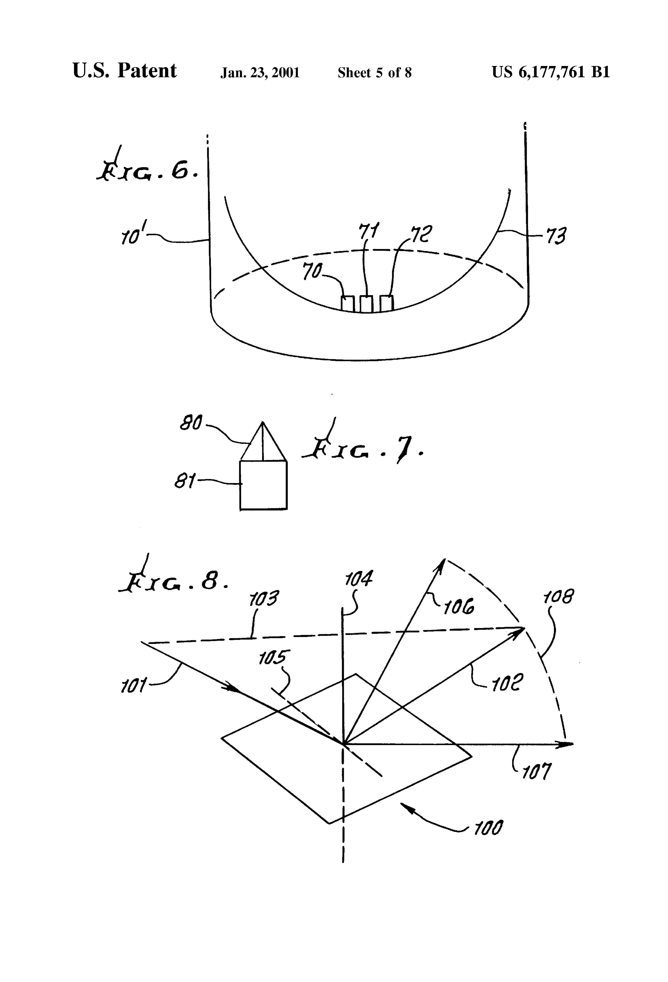
c) LED means located in Spaced relation to the pyramidal FIGS. 6 and 7 are elevations showing modifications; body, and oriented to transmit light in the cylindrical FIG. 8 is a diagram;
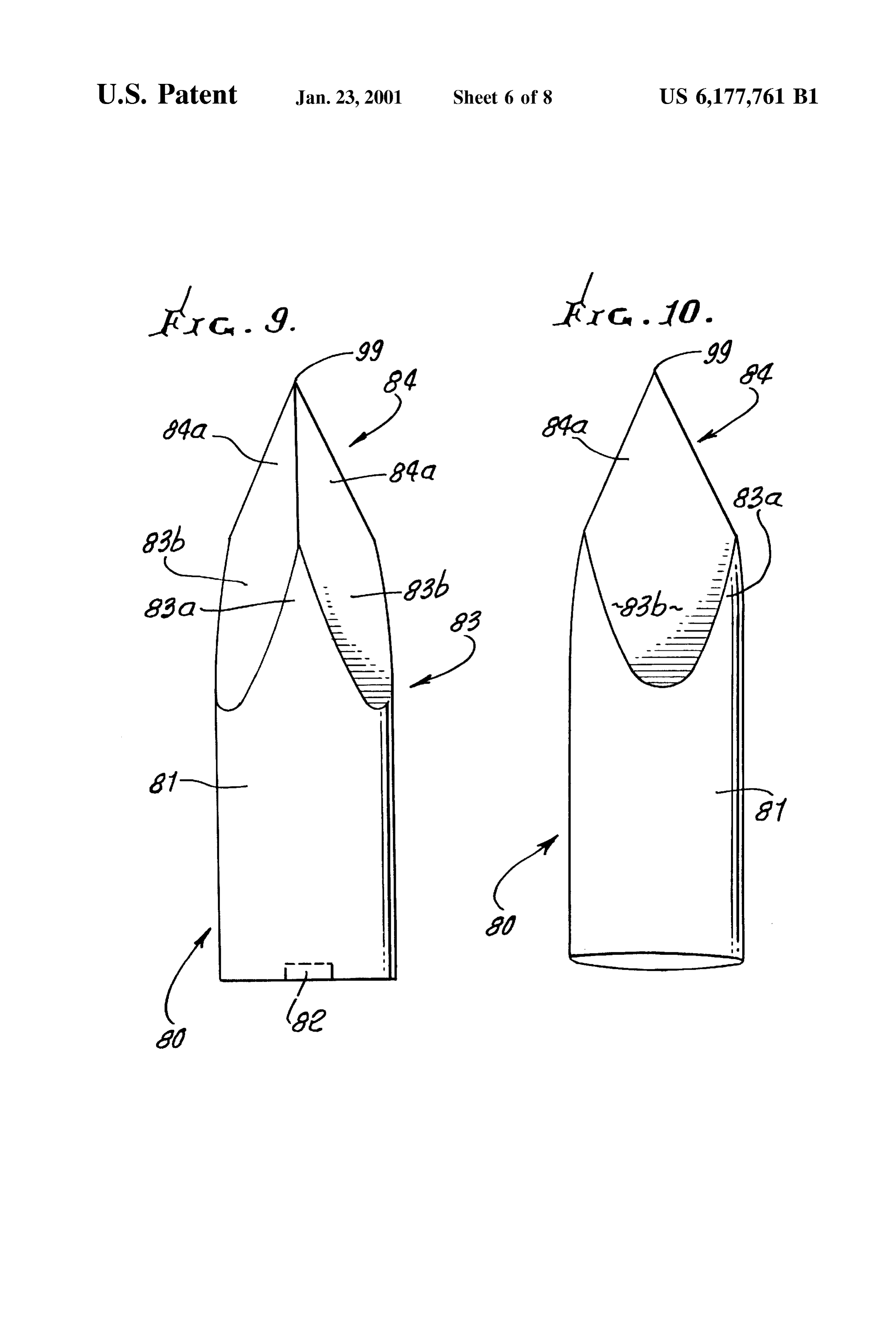
body and toward the pyramidal body. 55 FIG. 9 is a side elevation showing a modification; Such a device can attain efficiencies in excess of 90% in FIG. 10 is a view like FIG. 9, but taken toward one flat transferring light from a higher indeX of refraction material Side of the body upper portion;
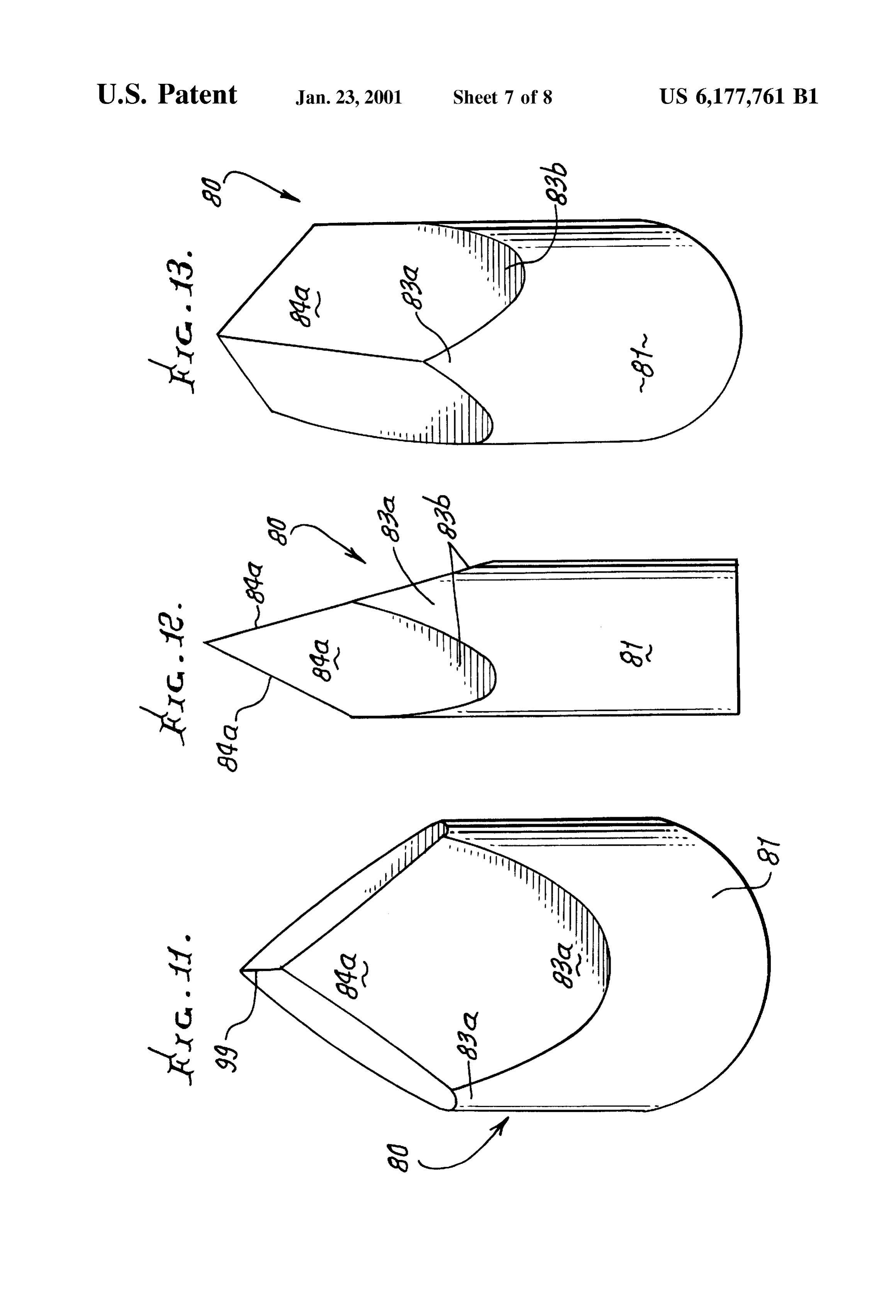
into air. Also, Such a device is much more compact than the FIG. 11 is a view like FIG. 10, but taken edgewise of the aplanatic device. one flat Side of the body upper portion; Comparison of the two Systems shows that the mono 60
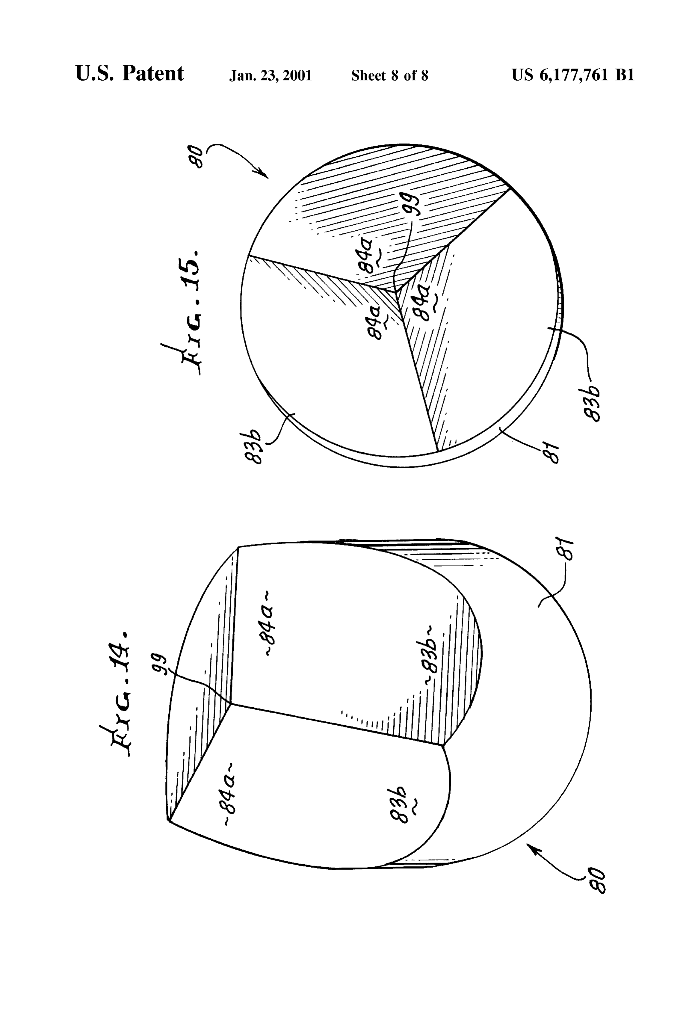
FIG. 12 is a perspective view of the FIG. 9 modification;
chrome LED aplanat System is Somewhat larger in diameter and has no ability to mix together light from an RGB LED FIG. 13 is a top perspective view of the FIG. 9 modifi triad, because the aplanat System is an imaging System cation;
whereas the LED pyramidal extractor is non-imaging and FIG. 14 is a top side perspective view of the FIG. 9 therefore a good RGB mixer. The new three-sided pyramidal 65 modification;
extractor disclosed herein has almost no losses due to FIG. 15 is another top and side perspective view of the Fresnel reflections, which are themselves extracted. While a FIG. 9 modification;
Page 11
DETAILED DESCRIPTION Also, provided are generally non-imaging reflector means Referring first to FIG. 1, a cylindrical body 10 of height associated with the one or more LED means 14. As shown, L-L consists of light transmitting material Such as thermo there be are three LEDs, in a cluster, at 14a, 14b and 14c. They Setting polymer, UV curable polymer or injection moldable may red, cylindrical as shown or rectangular. They may be green and blue light emitting LEDs, and means to material Such as acrylic or polycarbonate, all of the forego control ing materials with a common index of refraction in the 1.5 LEDs is shown the relative levels of light transmission from the at 19. FIGS. 1 and 3 show the LEDs as to 1.6 range. That body has a bottom 10a and a cylindrical centered within the cup-like reflectors 20a, 20b and 20c, side wall 10b. As shown, the body diameter D generally is which may consist of aluminum shells, with about 0.88 less than the axial height or length L+L. A pyramidal body 1O reflectivity. FIG. 2 shows the dimensions of a typical 11 of height L is located above the upper side of body 10, reflector, having a toroidal elliptical Surface. The reflector is and is shown as having a base 11a, and three sides 11b, 11c non-imaging, and acts to reflect light and 11d, and tip 11e. Base 11a is spaced above the plane of maximum angle Such that no light passesupwardly with a through cylinder the top of body 10, typically halfway between said tip 11e and the horizontal plane indicated at 13.a. walls 10b or 13. The material of body 10 fills the cup formed 15 by each reflector, about the LED in that cup.
Body 11 also consists of light transmitting material, which The geometry of the pyramidal extractor is depicted in may be the same as that of body 10. A third body 12 of height FIG. 1 and is formed by taking a cylinder with diameter D L is located between bodies 10 and 11, and may be unitary or integral therewith, whereby only one overall body is and Shaving off three planes. The geometry of the planes is provided, having first, second and third body regions 10, 11 described by two lengths L and L. The length of the and 12. The overall body may consist of plastic material, pyramidal region is L., while the total length of the extractor Such as thermosetting polymer or UV curable polymers. is L+L (L2 is the length of the extractor Surface that LED means generally is shown at 14, located in body 10 contains parts of the original i.e. lower cylinder). Each plane in Spaced relation to the pyramidal body region 11, and 11a. All planesbyshare is determined three points that are the vertices of triangle a common point at the tip (0,0,L+L).
oriented to transmit light in body 10 and toward body 11, for 25 The other points for the i' plane (i=1,2,3) are (Rcos(21i)/3, example through region 12. Region 12 may be characterized Rsin(2 ti)/3, L.) and (Rcos(2 (i+1))/3, Rsin(2 (i+1))/3, L.), as acting to mix light transmission of different wavelengths, from multiple LEDs, and body 11 may be characterized as where R=D/2 is the cylinder radius. In order for the cylin in the path of light transmission from region 12, body 11 drical region in FIG. 1 to have a finite length (and allow the being of reduced volume, and from which light is efficiently extractor to be coupled to a circular aperture), the condition L>L must be satisfied. When L=L, the faces 11b', 11c', transmitted into the Surrounding air. and 11d" are coplanar with faces 11b, 11c, and 11d, respec Second body region 12 typically has modified cylindrical tively. In the FIG. 1 design, the metal reflector cusp and LED shape, i.e. with a wall 13 that is a continuation of cylindrical (depicted in FIG. 4) are embedded inside the cylindrical side wall 10b, and with a circular base indicated at 13a region 10, which has height L-L.
coincident with or integral with the upper side of body 10. 35 FIG. 5 is a Summary table comparing the performance of If bodies 10 and 12 are integral, as is preferred, then the top of 10 and the base of 12 are unitary, i.e. no physically the present pyramidal extractor with the hemispherical aplanat System of the prior art. Only light rays exiting with coincident surfaces exist, and the bodies 10, 11 and 12 may a positive direction vertically are considered extracted, then be unitary and homogeneous. Wall 13 is cylindrical between planar Surface areas 11b', 11c' and 11d which are 40 resultingAS in a loss of around 1% for both systems.
respects operation, consider a pyramidal Structure of downward continuations of the body 11 pyramid planes 11b, 11c and 11d, respectively. Planes 11b, 11c', and 11d" are high index of refraction material and low Symmetry, Say alike, and Spaced equidistantly about the vertical axis 15 of 3-sided. Even if the light distribution is hemispherical at the the Overall body; also, those planes interSect the cylindrical base, essentially all of the light will emerge or be turned Surface 13 along elliptical Section lines 16 that are curved, 45 back by phase Space conservation. In a Situation of high and tangent at 17 to the upper edge circle 13a defined by the Symmetry, Say rotational Symmetry, the skew invariant will uppermost full horizontal extent of the body 10. Line 13a cause much of the light to turn back. But in a situation of low also shows a plane defined by tangent points 17. Symmetry Such as a 3-sided pyramid, there is no invariance A variation of this invention includes micro-optical means principle that requires rays to turn back, and by varying the on Some or all Surfaces whereby total internal reflection is 50 the light is asturned taper angle an adjustable parameter, essentially none of back. It is important to note that the laterally Scattered. That is, an internally reflected ray will fraction of light extracted continue upwards but will be fanned out into a sheet of rayS, a single Fresnel reflection,considerably exceeds even that of because of multiple reflections thereby promoting mixing. Conventional Scattering means inside the extractor. Therefore, essentially all of the light is would send too much energy back down the extractor, to be extracted.
lost, Instead, a holographic diffuser with a narrow elliptical 55
Scattering pattern oriented circumferentially on the extractor Ideally, the extractor will be of the same index material as would help mix the colors. In FIG. 8 a small portion of a and in optical contact with the LED material. If made of a surface is shown, with tangent plane 100. Tangent plane 100 lesser index material, Say nas 1.5, at least all of the light reflects ray 101 into ray 102. Both said rays lie in plane 103, already inside the nas 1.5 material will emerge. This is which is orthogonal to plane 100, and contains surface 60 Significantly better than achieved by current practice. normal 104. Line 105 indicates a circumference of the Pyramidal extractors have been proposed and used for invention. Scattered rays 106 and 107 form plane 108, which high flux Solar energy concentration. The Weizmann Insti is orthogonal to plane 103. Said scattered rays form the tute of Science group in Rethoven, Israel (Amnon Yogev, limiting angles of a fan of rays into which ray 102 is Harald Ries, A. Segal and Jacob Karni) has used them in smeared. Plane 100 could either have a circumferentially 65 conjunction with dielectric CPC nonimaging cones for a oriented elliptical-patterned holographic diffuser or a dif high temperature receiver in a Solar furnace. The University fraction grating to implement the Scattering pattern. of Chicago group (Roland Winston, David Jenkins, Joe
Page 12
S 6
O'Gallagher) has used them in conjunction with dielectric body outer wall at curved edges, Said cylindrical outer CPC nonimaging cone in a Solar furnace to achieve a wall terminating at Said curved edges, concentration of 50,000 Suns. c) LED means located in Spaced relation to said pyramidal The radiation pattern at an LED Surface can be deduced body, and oriented to transmit light in Said cylindrical by considering the LED inside a cavity with index ns 1 in body and toward Said pyramidal body. equilibrium with its own radiation. Then applying the Kir The apparatus shown in FIGS. 9-15, as in FIG. 1, also choff relations, the emissivity may be defined to comprise:
a) a transparent body 80 having a first region 81 which is cylindrical and in which the LED’s 82 are at least partly
received,
Here, c1(0, ) is the absorptivity, 0 is the angle with b) said body having a second and upper region 83 in the respect to the surface normal of the LED and It is the upward paths of light transmission from the LEDs, and polarization. Dependence on other variables Such as wave acting to mix Such light transmission, length) has been Suppressed. Now p(0, ) is just the Fresnel 15 c) said body 80 having a third uppermost region 84 in the reflection coefficient at the nas1, nas3 interface, which is path of light transmission from the Second region, Said (n-1)/(n+1). This formula can be found, for example in third region being of reduced volume from which Born and Wolf, Principles of Optics (6' edition, page 40). mixed light is transmitted, It follows that the angular distribution can be modeled as:
d) said second region having a discontinuous cylindrical surface shape at 83a between planar surface areas 83b which are downward continuations of three planes 84a where S2 is the Solid angle of emission. defined by sides of said third region, which has three This means that the angular distribution is more peaked in sided pyramid form, the forward direction than a simple lambertian distribution e) said planar Surface areas 83b intersecting said Surface (C.coS0). This result is expected to closely model an ergodic 25 83a along curved lines which are portions of ellipses. Situation Such as the regular Volume of, an LED, but not the The body apex appears at 99. The apparatus of FIGS. extractor, where the light distribution is best obtained by 9-15 performs the same functions as does the FIGS. 1-8 detailed ray-tracing. apparatuS.
The LEDs are typically formed as cubes, each having a From the foregoing and the drawings, it will be noted that bottom conductor layer (cathode) as at 60 in FIG. 4, a top the light transmitting pyramid sides define planes extending anode 61, an intermediate PIN junction 62, and body 63. upwardly toward an apex that is spaced in a longitudinal LED compositions determine the color of emitted light. direction from the LED, those planes Steeply angled, at LEDs are known, and Supplied by companies Such as angles in excess of 45, relative to a lateral plane normal to Hewlett Packard Corp., Toshiba Corp. and Sony Corp. The reflectors as described are typically thin metallic Stampings. 35 Said longitudinal direction Such that essentially all LED light As shown in FIG. 4, depicting only one of the three RGB extracted onfrom incident Said three sides from within the pyramid is
Said SideS.-See for example the planar
LED's in body 10, the height H of the reflector cup, above angularities in FIGS. 1 and 9-13. the level of the bottom of the LED cube, must be such that We claim:
the extreme rays 64 from the LED reach the cylindrical wall 1. In apparatus to extract light from an LED, the combi 10b of body 10 at an angle 0 that is greater than 0 = arcsin 40 nation comprising (1/n), which is the critical angle for total internal reflection. a) a cylindrical body consisting of light transmitting 0=42 for n=1.5. Thus, all light or essentially all light from the three RGB LEDs is reflected back into, and upwardly, in material, Said body having a cylindrical outer wall, body 10 for mixing by multiple reflections off the walls of b) a pyramidal body having at least three planar Sides and 10, 11 and 12, to eventually exit the top pyramid. FIG. 6 45 consisting of light transmitting material, Said pyramidal shows three LEDs 70, 71, and 72 (red, green and blue light body located longitudinally endwise of Said cylindrical emitting) placed in one hemispherical reflector 73, all body, to expose Said three or more sides, Said planar embedded in cylindrical body 10' (below regions 11 and 12, Sides defining planes which interSect Said cylindrical as before), to produce light mixing. body outer wall at curved edges, Said cylindrical outer FIG. 7 shows another modification, wherein a three-sided 50 wall terminating at Said curved edges, light transmitting pyramid 80 is located at the top of an LED c) LED means located in Spaced relation to said pyramidal 81, for transmitting light upwardly. It is preferable that the body, and oriented to transmit light in Said cylindrical LED substrate have relatively low absorption, so as to allow body and toward Said pyramidal body, the extractor pyramid Sufficient optical path length for d) said planes extending upwardly toward an apex that is efficient transmission outwards. 55 Spaced In a longitudinal direction from the LED means, In the modifications shown in FIGS. 9-15, the elements Said planes angled in excess of 45 relative to a lateral corresponding to those of FIG. 1 bear the same identifying plane normal to Said longitudinal direction Such that numerals. essentially all LED light incident on said sides from The apparatus shown in FIGS. 9-15, as in FIG. 1, includes within the pyramid is extracted. or comprises: 60 2. The combination of claim 1 wherein said LED means a) a cylindrical body consisting of light transmitting is located within reflector means, in alignment with Said material, Said body having a cylindrical outer wall, pyramidal body.
b) a pyramidal body having at least three planar Sides and 3. The combination of claim 2 wherein the reflector means consisting of light transmitting material, Said pyramidal has a height H characterized in that extreme rays from the body located longitudinally endwise of Said cylindrical 65 LED means in the reflector means are reflected by a wall or body, to expose Said three or more sides, Said planar walls associated with a body region or regions, back into the Sides defining planes which interSect Said cylindrical body region or regions.
Page 13
4. The combination of claim 3 wherein each LED is 8. The combination of claim 5 wherein said planes meet located in a separate reflector in the form of a cup. at an apex.
5. In apparatus to extract light from multiple LEDs, the 9. The combination of claim 8 wherein said first region combination comprising has a height L-L and said Second and third regions have a) a transparent body having a first cylindrical region in heights L and L, respectively, and where L>L. 10. The combination of claim 5 wherein there are three of which the LED's are at least partly received, Said LEDs, in a cluster.
b) said body having a second region in the paths of light 11. The combination of claim 10 including cup-shaped transmission from the LEDs, and acting to mix Such reflector means that include three cups which are clustered light transmission, and open toward Said Second region, the three LEDS located c) said body having a third region in the path of light respectively in Said cups.
transmission from the Second region, Said third region 12. The combination of claim 5 including means for being of reduced volume from which mixed light is controlling the relative emissions from the LEDs. transmitted, 13. The combination of claim 5 wherein said LEDs are d) said second region having discontinuous cylindrical 15 located within reflector means, in alignment with the pyra Surface shape between planar Surface areas which are midal body, and said reflector means and LEDs are both continuations of three planes defined by Sides of Said located at least partly within Said body. third region. 14. The combination of claim 5 wherein said three LEDs 6. The combination of claim 5 wherein said third region emitting red, green and blue light are located within one has pyramid shape. reflector in the form of a cup. 7. The combination of claim 5 wherein said third region has pyramid shape. k k k k k
Provenance
- Collection
- Patents citing this work
- Original assignee
- Teledyne Lighting and Display Products Inc
- Current assignee
- Seoul Semiconductor Co Ltd
- Pages
- 13
- Method
- pdftotext (the PDF's own text layer) + pdftoppm 300dpi page scans
- Patent office record
- patents.google.com →
- Source
- Google Patents citing-documents table
- Inventors
- David G. Pelka; Roland Winston; William A. Parkyn, Jr.; Teledyne Lighting and Display Products Inc
- Published
- 2001-01-23
- Transcribed from
- patentimages.storage.googleapis.com →