patent · US5255171
Colored light source providing intensification of initial source illumination
19 October 1993
Page 1
HHHHHHHHHHHHHHHHHHIII
United States Patent (19) (11) Patent Number: 5,255,171 Clark 45) Date of Patent: Oct. 19, 1993 54) COLORED LIGHT SOURCE PROVIDING OTHER PUBLICATIONS
NTENSIFICATION OF INTAL SOURCE
LLUMNATON Roland Winston, Scientific American, "Nonimaging
76) Inventor: L. Douglas Clark, 15 Conrad St., San
Francisco, Calif. 94131 Primary Examiner-Richard R. Cole
Attorney, Agent, or Firm-D. Pressman
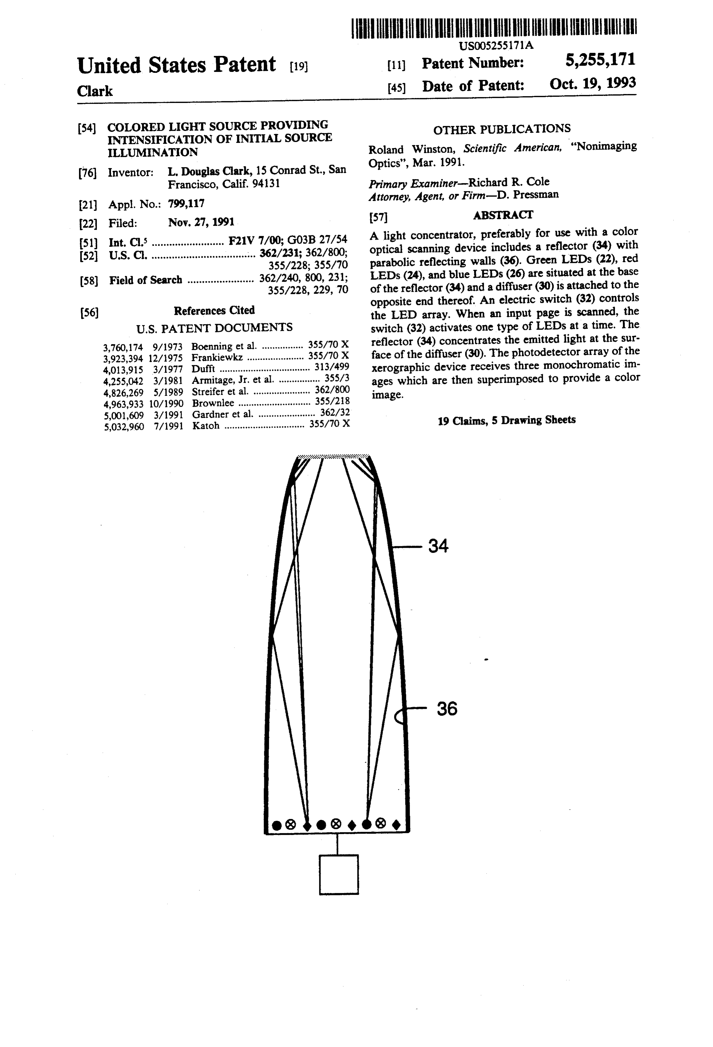
A light concentrator, preferably for use with a color (51) Int, C. ......................... F21V 7/00; G03B 27/54 optical scanning device includes a reflector (34) with (52) U.S. C. .................................... 362/231; 362/800;
355/228; 355/70 parabolic reflecting walls (36). Green LEDs (22), red (58) Field of Search ....................... 362/240, 800, 231; LEDs (24), and blue LEDs (26) are situated at the base 355/228, 229, 70 of the reflector (34) and a diffuser (30) is attached to the
References Cited opposite end thereof. An electric switch (32) controls (56) the LED array. When an input page is scanned, the
3,760,174 9/1973 Boenning et al. ................ 355/70 X reflector (34) concentrates the emitted light at the sur 3,923,394 12/1975 Frankiewkz . 355/70 X face of the diffuser (30). The photodetector array of the 4,013,915 3/1977 Dufft ....................... 313/499 xerographic device receives three monochromatic im 4,255,042 3/1981 Armitage, Jr. et al. ................ 355/3 ages which are then superimposed to provide a color 4,826,269 5/1989 Streifer et al. .......... ... 362/800 image.
4,963,933 10/1990 Brownlee ............ ... 355/218 5,001,609 3/1991 Gardner et al. ...................... 362/32 19 Claims, 5 Drawing Sheets 5,032,960 7/1991 Katoh ............................... 355/70 X
Page 2
Drawing sheet — no readable text.
Page 3
Drawing sheet — no readable text.
Page 4
Drawing sheet — no readable text.
Page 5
Drawing sheet — no readable text.
Page 6
Drawing sheet — no readable text.
Page 7
article, an optical device that concentrates light by
COLORED LIGHT SOURCE PROVIDING forming an image will blur that image away from the INTENSIFICATION OF NITIAL SOURCE focal point. Consequently, a maximum concentration of LLUMINATION light can be attained only when the image-forming re quirements are disregarded. In his experiments, Win
BACKGROUND ston uses a solar energy concentrator, which is essen 1. Field of Invention tially a funnel. Light entering the large side of the fun The present invention relates to light sources and of nel is reflected from the walls of the funnel so that most it passes out through the small side of the funnel, thus concentrators, specifically to light sources that provide 10 destroying concentrated light of various colors, especially for opti light source.any imaging order (image) present in the However, if only concentration of light is cal scanning systems. Such optical scanning systems include, but are not limited to xerographic devices, line desired, there is no need for image formation. The article also describes a solar concentrator having scan imaging systems, and area scan imaging systems.
Common embodiments of these scanners include com 15 hyperbolic walls. Such a device is useful when light puter-input and flat-bed page scanners, such as the must be concentrated on a flat surface. While this de model HP9195A manufactured by Hewlett Packard vice is able to concentrate light, it lacks any capability Company of Palo Alto, Calif. U.S.A. and sold under the for use in color copiers or scanners, where concentrated trademark "Scan Jet Plus'. light of various colors must be supplied at respectively 2. Description of Prior Art different times.
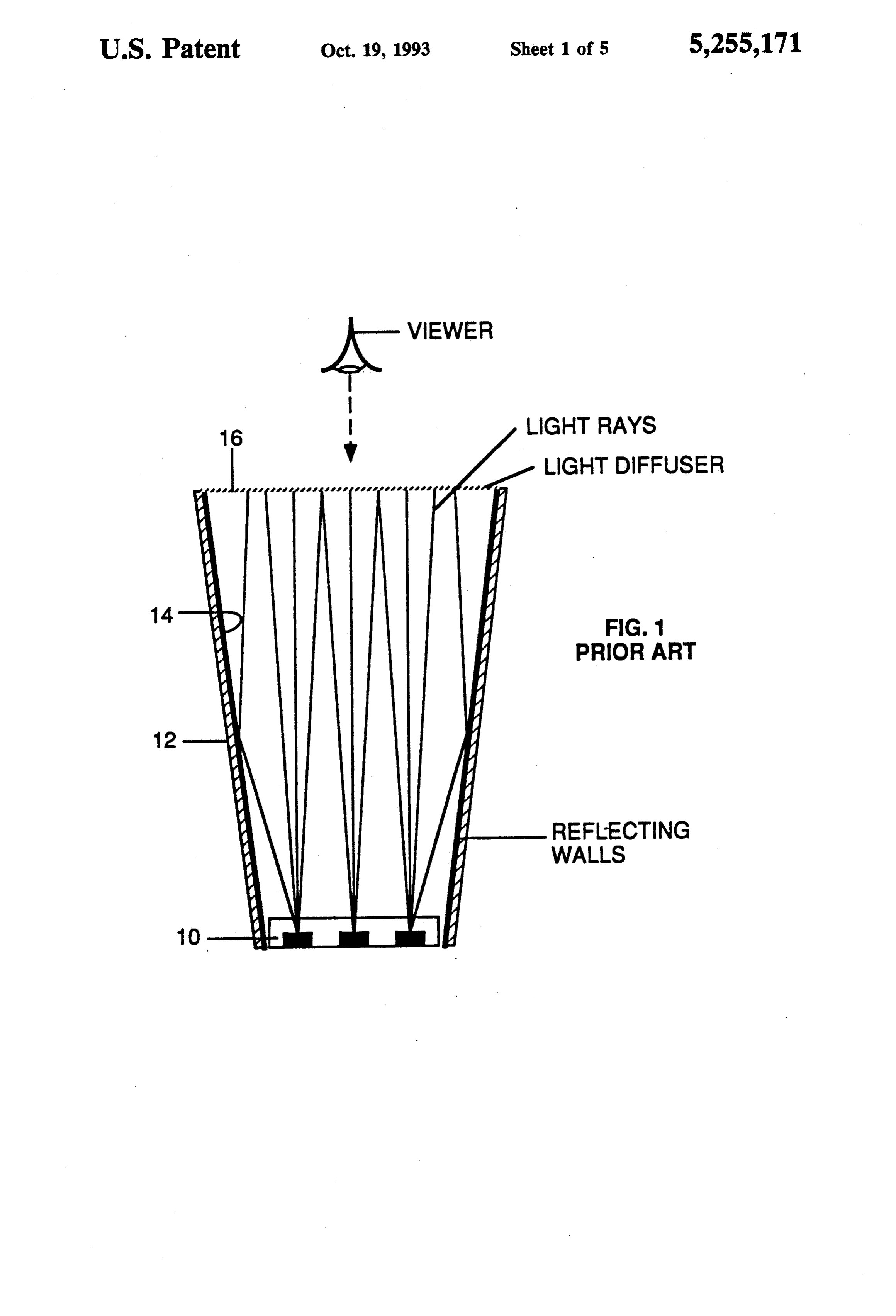
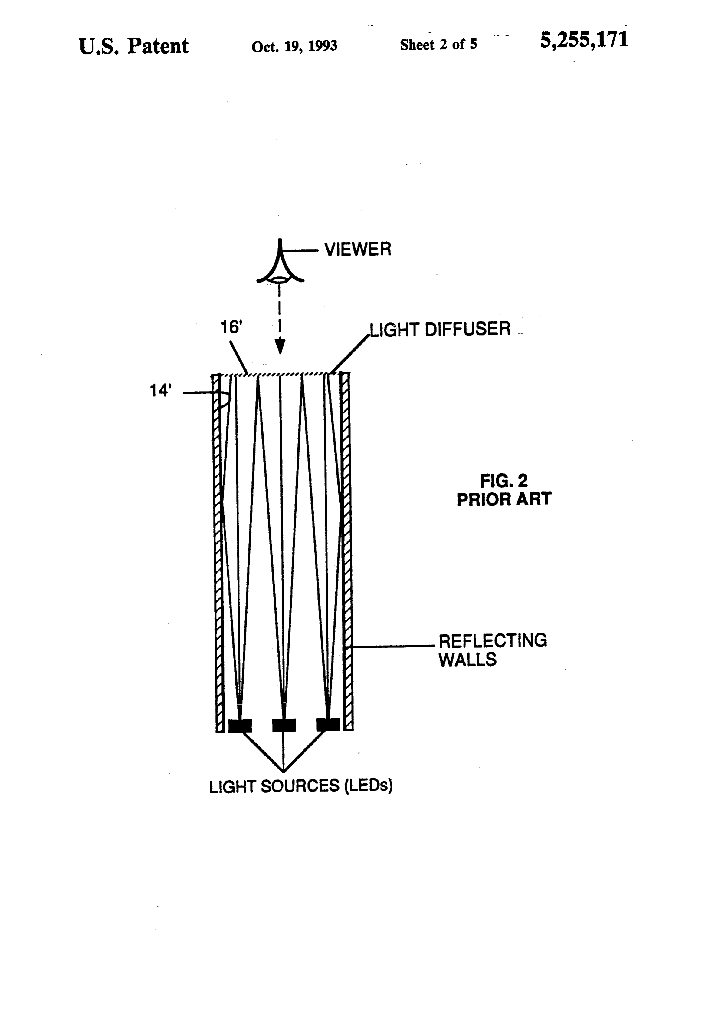
It is desirable to obtain the highest possible concen- 20 OBJECTS AND ADVANTAGES tration of light, for instance, in illumination systems of optical scanners in order to maximize the dynamic It is accordingly an object of the invention to provide range of such devices. a light concentrator which overcomes the foregoing Prior art illuminators are shown in U.S. Pat. Nos. disadvantages, which can be used to supply concen 4,013,915 to W. H. Duft (1977), 4,225,042 to J. D. Ar- 25 trated light of different colors at respective different mitage (1981), 4,963,933 to Kenneth Brownlee (1990), times or simultaneously, which enhances the image and 5,001,609 to Robert Gardner et al. (1991). These quality of color monochrome scanning, which increases illuminators are of the types depicted in FIGS. 1 and 2. the speed of the image input scanning process, and The illuminator shown in FIG. 1 uses a light source which eliminates mechanical complexity. Further ob 10, which comprises several individual sources posi 30 jects and advantages will become apparent after consid tioned at the base of a reflector 12. Reflector 12 has eration of the ensuing description and the accompany reflecting walls 14 which diverge outwardly. The cross ing drawings.
section of this prior-art illuminator has a salient geomet ric shape such as conical (not shown), or it may extend DRAWING FIGURES any length perpendicular to its cross section. A diffuser 35 FIG. 1 is a schematic diagram of a prior-art illumina 16 is located at the diverging end of reflector 12. As tor having diverging sides.
light is emitted by source 10, it will spread out. Some will proceed directly to diffuser 16, spreading out torFIG. having 2 is a schematic drawing of a prior-art illumina parallel sides.
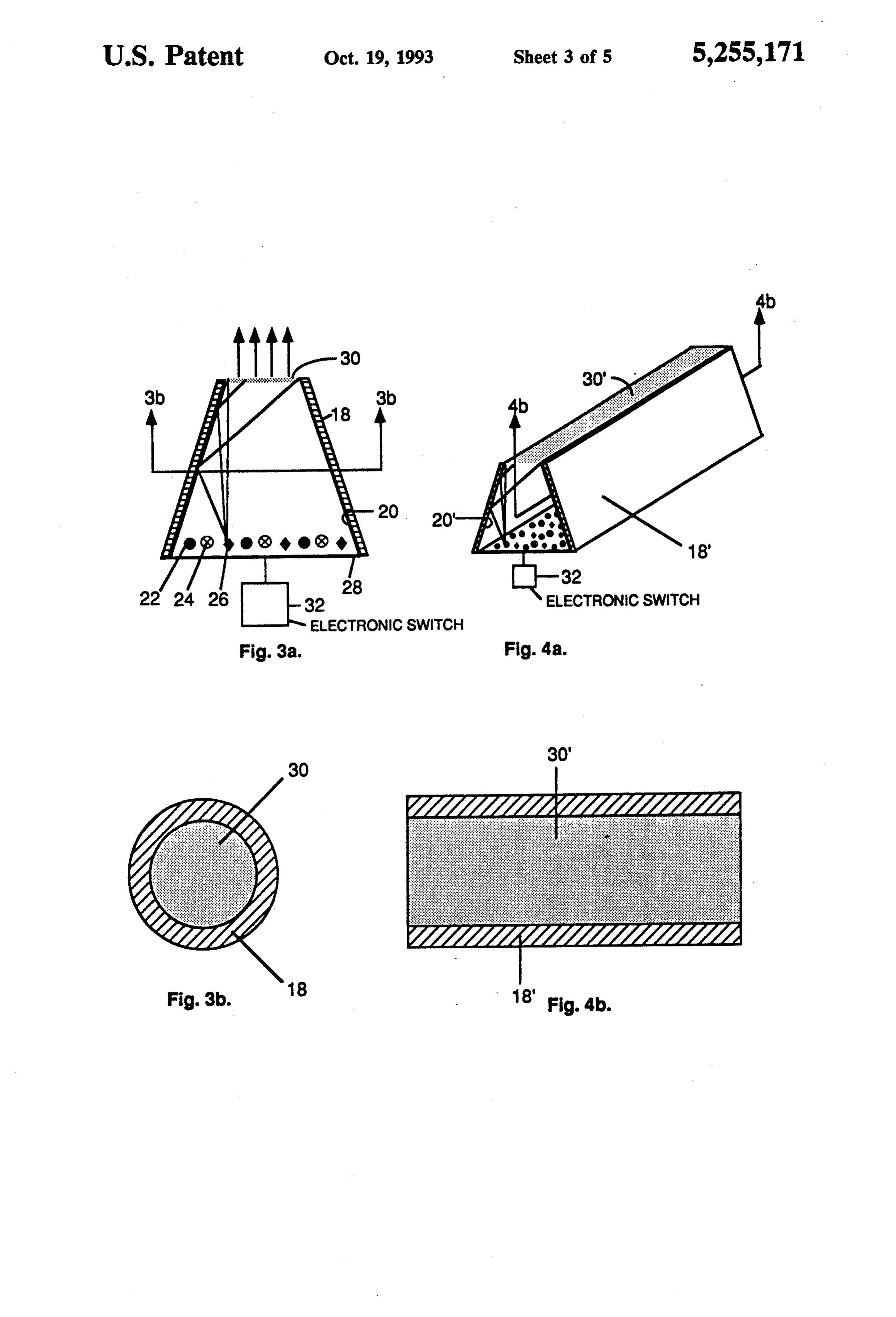
slightly as indicated, and some will be reflected from FIG. 3a is a schematic cross-sectional drawing of a walls 14, as also indicated. As a result, most of the light 40 conical light emitted by source 10 will shine through diffuser 16 and invention, and concentrator according to the present the surface of diffuser 16 will appear to be uniformly trator of FIG. 3a taken in the directionofindicated FIG. 3b is a cross-section the concen
illuminated. lines 3a-3a,
However, the illumination intensity at the surface of FIG. 4a is a perspective view of a trapezoidal concen diffuser 16 is much less than that of source 10 since light 45 trator is dispersed from the relatively small surface of source tional accordingview taken to the invention and FIG. 4b is a sec in the direction indicated by lines 10 to cover the much larger area of diffuser 16. 4b-4b. s FIG. 2 shows a modification of the illuminator of
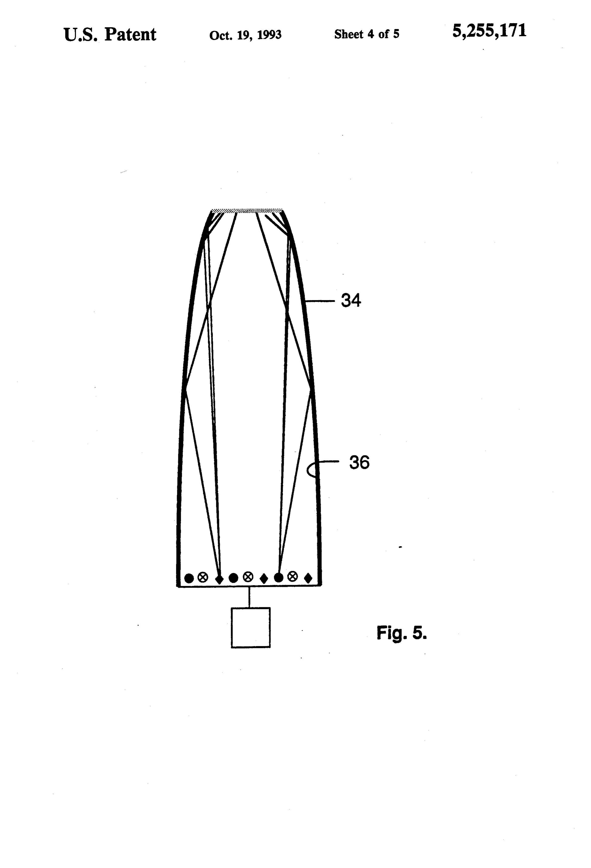
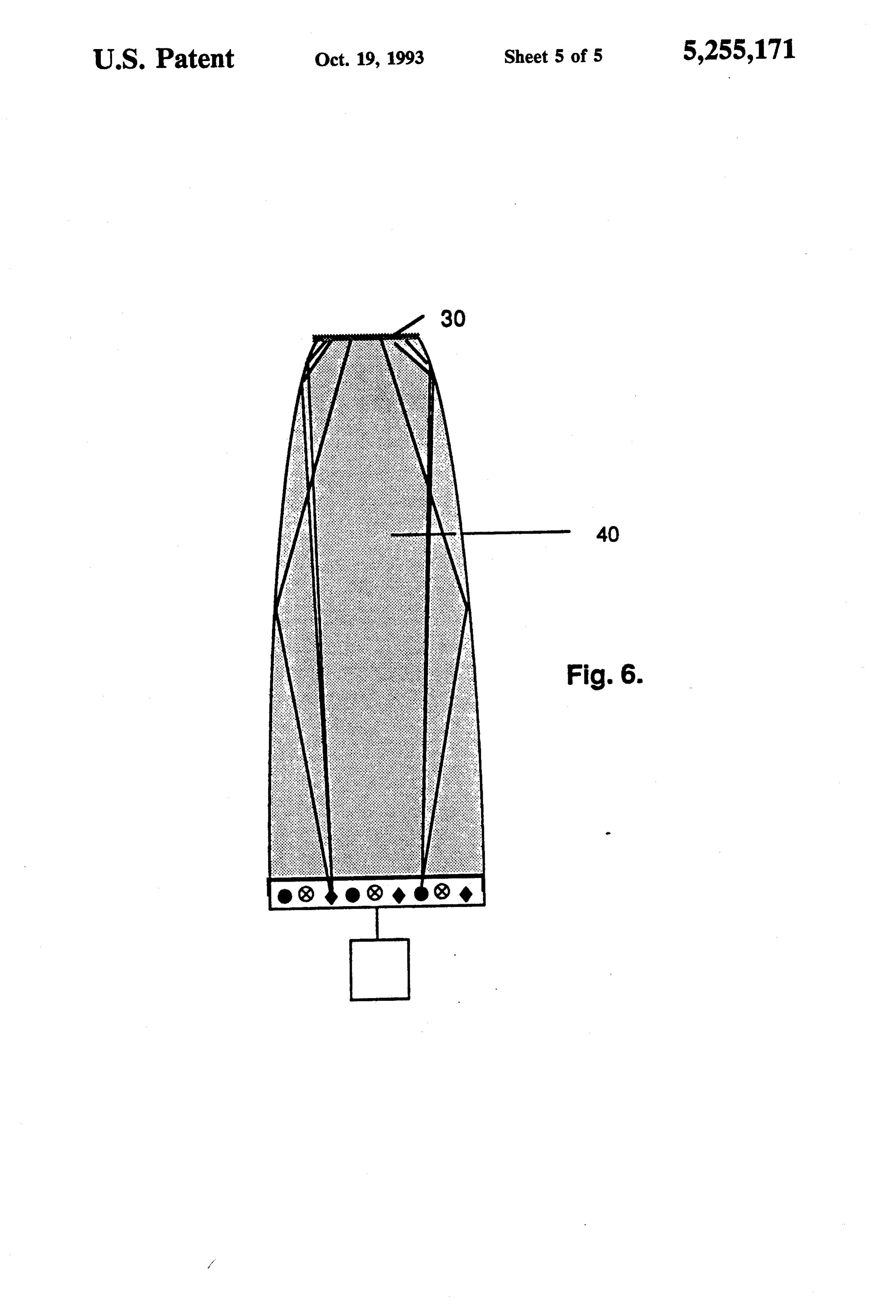
FIG. 1. In this case, reflecting walls 14' are parallel to FIG. 5 is a schematic drawing of a variation of the each other, so that the light source and the diffuser areas 50 light concentrator shown in FIG. 3. FIG. 6 is a schematic drawing of a variation of the are equal. Here, the light intensity at the surface of the light diffuser, here designated 16', is somewhat greater than guide.concentrator using a solid plastic or glass light the light intensity at the surface of diffuser 16 of FIG. 1, It is to be noted that for purposes of illustration, these but is still less than the intensity of the light source.
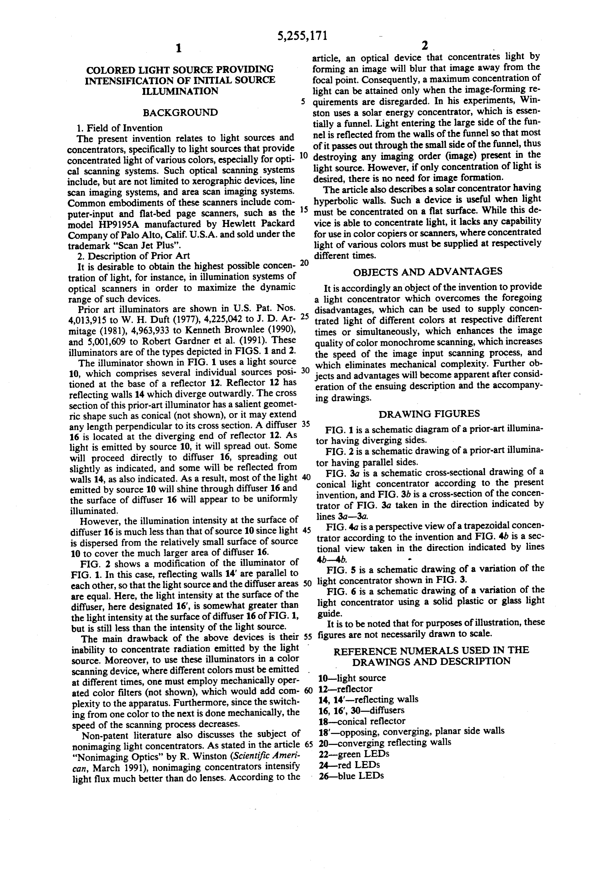
The main drawback of the above devices is their 55 figures are not necessarily drawn to scale. inability to concentrate radiation emitted by the light REFERENCE NUMERALS USED IN THE source. Moreover, to use these illuminators in a color DRAWINGS AND DESCRIPTION scanning device, where different colors must be emitted 10-light source at different times, one must employ mechanically oper 12-reflector ated color filters (not shown), which would add com plexity to the apparatus. Furthermore, since the switch 14, 14'-reflecting walls
ing from one color to the next is done mechanically, the 18-conical speed of the scanning process decreases. reflector 18'-opposing, converging, planar side walls
Non-patent literature also discusses the subject of 20-converging nonimaging light concentrators. As stated in the article 65 reflecting walls "Nonimaging Optics" by R. Winston (Scientific Ameri 22-green LEDs can, March 1991), nonimaging concentrators intensify 24-red LEDs light flux much better than do lenses. According to the 26-blue LEDs
Page 8
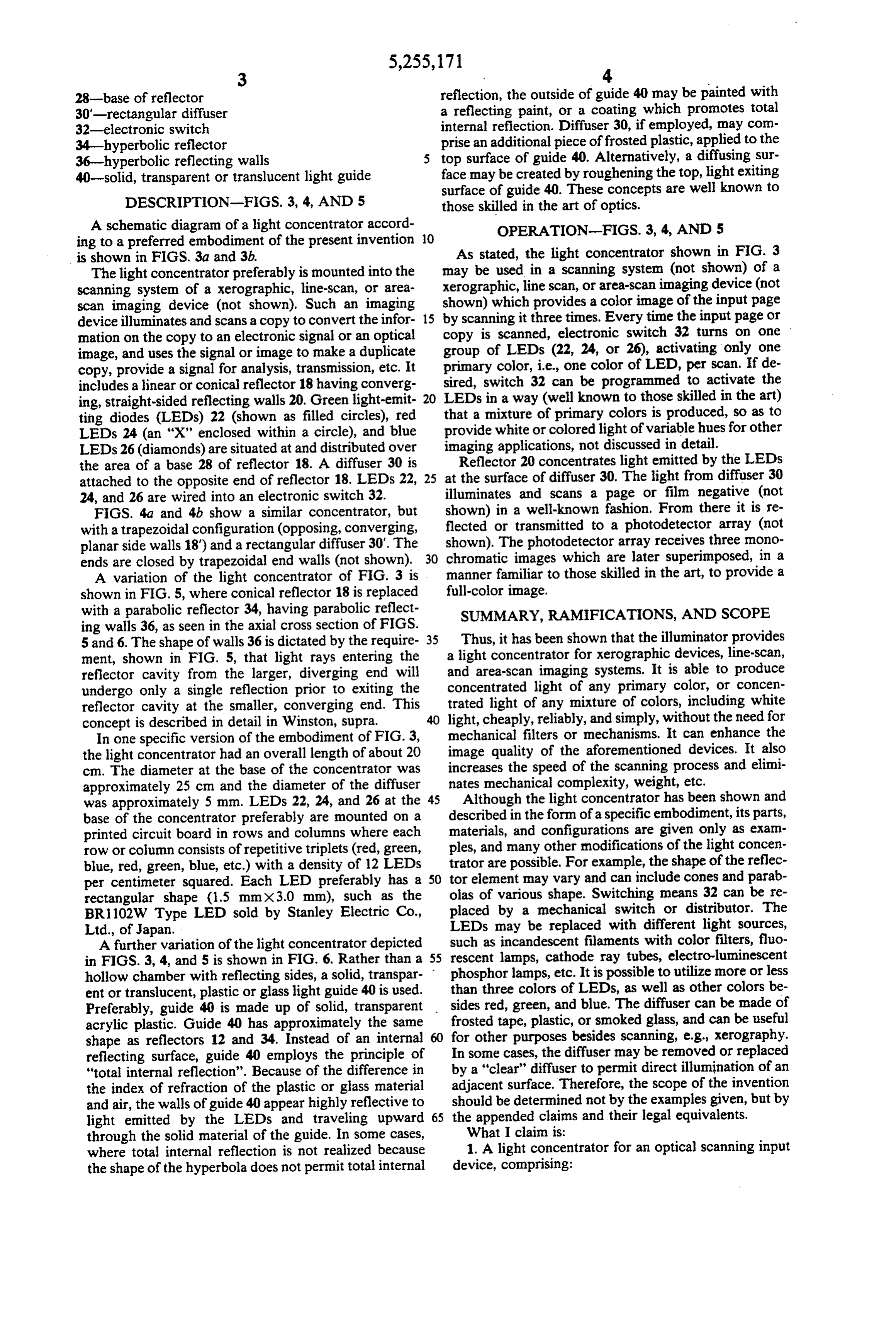
28-base of reflector reflection, the outside of guide 40 may be painted with 30'-rectangular diffuser a reflecting paint, or a coating which promotes total 32-electronic switch internal reflection. Diffuser 30, if employed, may com 34-hyperbolic reflector prise an additional piece of frosted plastic, applied to the 36-hyperbolic reflecting walls top surface of guide 40. Alternatively, a diffusing sur 40-solid, transparent or translucent light guide face may be created by roughening the top, light exiting surface of guide 40. These concepts are well known to
DESCRIPTION-FIGS. 3, 4, AND 5 those skilled in the art of optics.
A schematic diagram of a light concentrator accord OPERATION-FIGS. 3, 4, AND 5 ing to a preferred embodiment of the present invention 10 is shown in FIGS. 3a and 3b. As stated, the light concentrator shown in FIG. 3 The light concentrator preferably is mounted into the may be used in a scanning system (not shown) of a scanning system of a xerographic, line-scan, or area xerographic, line scan, or area-scan imaging device (not scan imaging device (not shown). Such an imaging shown) by which provides a color image of the input page scanning it three times. Every time the input page or device illuminates and scans a copy to convert the infor 15 mation on the copy to an electronic signal or an optical copy is scanned, electronic switch 32 turns on one image, and uses the signal or image to make a duplicate group of LEDs (22, 24, or 26), activating only one copy, provide a signal for analysis, transmission, etc. It primary color, i.e., one color of LED, per scan. If de includes a linear or conical reflector 18 having converg sired, switch 32 can be programmed to activate the ing, straight-sided reflecting walls 20. Green light-emit 20 LEDs in a way (well known to those skilled in the art) ting diodes (LEDs) 22 (shown as filled circles), red that a mixture of primary colors is produced, so as to LEDs 24 (an "X" enclosed within a circle), and blue provide white or colored light of variable hues for other LEDs 26 (diamonds) are situated at and distributed over imaging applications, not discussed in detail. the area of a base 28 of reflector 18. A diffuser 30 is Reflector 20 concentrates light emitted by the LEDs attached to the opposite end of reflector 18. LEDs 22, 25 at the surface of diffuser 30. The light from diffuser 30 24, and 26 are wired into an electronic switch 32. illuminates and scans a page or film negative (not FIGS. 4a and 4b show a similar concentrator, but shown) in a well-known fashion. From there it is re with a trapezoidal configuration (opposing, converging, flected or transmitted to a photodetector array (not planar side walls 18') and a rectangular diffuser 30'. The shown). The photodetector array receives three mono ends are closed by trapezoidal end walls (not shown). 30 chromatic images which are later superimposed, in a A variation of the light concentrator of FIG. 3 is manner familiar to those skilled in the art, to provide a shown in FIG. 5, where conical reflector 18 is replaced full-color image.
with a parabolic reflector 34, having parabolic reflect SUMMARY, RAMIFICATIONS, AND SCOPE ing walls 36, as seen in the axial cross section of FIGS.
5 and 6. The shape of walls 36 is dictated by the require 35 Thus, it has been shown that the illuminator provides ment, shown in FIG. 5, that light rays entering the a light concentrator for xerographic devices, line-scan, reflector cavity from the larger, diverging end will and area-scan imaging systems. It is able to produce undergo only a single reflection prior to exiting the concentrated light of any primary color, or concen reflector cavity at the smaller, converging end. This trated light of any mixture of colors, including white concept is described in detail in Winston, supra. 40 light, cheaply, reliably, and simply, without the need for In one specific version of the embodiment of FIG. 3, mechanical filters or mechanisms. It can enhance the the light concentrator had an overall length of about 20 image quality of the aforementioned devices. It also cm. The diameter at the base of the concentrator was increases the speed of the scanning process and elimi approximately 25 cm and the diameter of the diffuser nates mechanical complexity, weight, etc. was approximately 5 mm. LEDs 22, 24, and 26 at the 45 Although the light concentrator has been shown and base of the concentrator preferably are mounted on a described in the form of a specific embodiment, its parts, printed circuit board in rows and columns where each materials, and configurations are given only as exam row or column consists of repetitive triplets (red, green, ples, and many other modifications of the light concen blue, red, green, blue, etc.) with a density of 12 LEDs trator are possible. For example, the shape of the reflec per centimeter squared. Each LED preferably has a 50 tor element may vary and can include cones and parab rectangular shape (1.5 mm x 3.0 mm), such as the olas of various shape. Switching means 32 can be re BR1102W Type LED sold by Stanley Electric Co., placed by a mechanical switch or distributor. The Ltd., of Japan. LEDs may be replaced with different light sources, A further variation of the light concentrator depicted such as incandescent filaments with color filters, fluo in FIGS. 3, 4, and 5 is shown in FIG. 6. Rather than a 55 rescent lamps, cathode ray tubes, electro-luminescent hollow chamber with reflecting sides, a solid, transpar phosphor lamps, etc. It is possible to utilize more or less ent or translucent, plastic or glass light guide 40 is used. than three colors of LEDs, as well as other colors be Preferably, guide 40 is made up of solid, transparent sides red, green, and blue. The diffuser can be made of acrylic plastic. Guide 40 has approximately the same frosted tape, plastic, or smoked glass, and can be useful shape as reflectors 12 and 34. Instead of an internal 60 for other purposes besides scanning, e.g., xerography. reflecting surface, guide 40 employs the principle of In some cases, the diffuser may be removed or replaced "total internal reflection'. Because of the difference in by a "clear' diffuser to permit direct illumination of an the index of refraction of the plastic or glass material adjacent surface. Therefore, the scope of the invention and air, the walls of guide 40 appear highly reflective to should be determined not by the examples given, but by light emitted by the LEDs and traveling upward 65 the appended claims and their legal equivalents. through the solid material of the guide. In some cases, What I claim is:
where total internal reflection is not realized because 1. A light concentrator for an optical scanning input the shape of the hyperbola does not permit total internal device, comprising:
Page 9
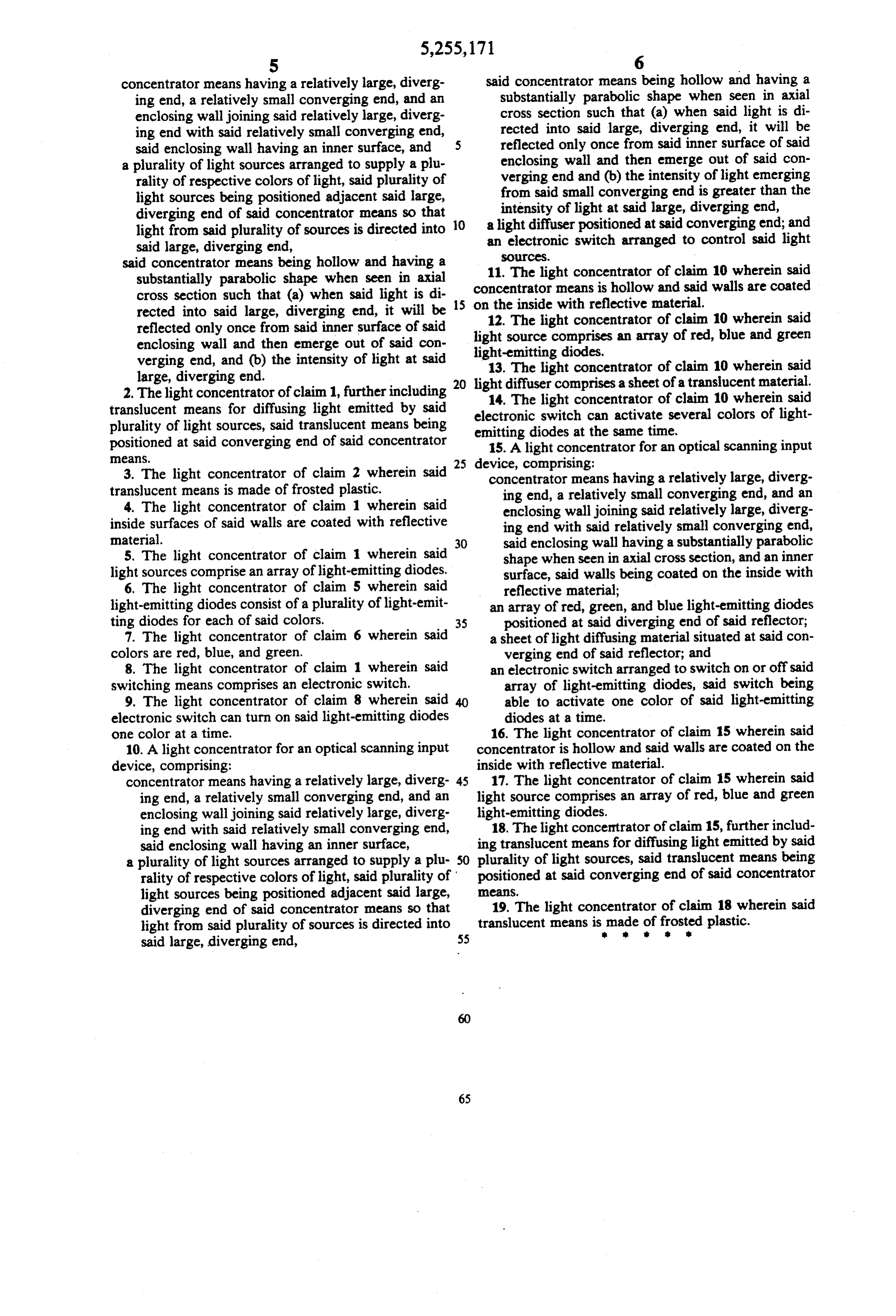
concentrator means having a relatively large, diverg said concentrator means being hollow and having a ing end, a relatively small converging end, and an substantially parabolic shape when seen in axial enclosing wall joining said relatively large, diverg cross section such that (a) when said light is di ing end with said relatively small converging end, rected into said large, diverging end, it will be said enclosing wall having an inner surface, and reflected only once from said inner surface of said a plurality of light sources arranged to supply a plu enclosing wall and then emerge out of said con rality of respective colors of light, said plurality of verging end and (b) the intensity of light emerging light sources being positioned adjacent said large, from said small converging end is greater than the diverging end of said concentrator means so that 10 intensity of light at said large, diverging end, light from said plurality of sources is directed into a light diffuser positioned at said converging end; and said large, diverging end, an electronic switch arranged to control said light sources.
said concentrator means being hollow and having a 11. The light concentrator of claim 10 wherein said substantially parabolic shape when seen in axial concentrator means is hollow and said walls are coated cross section such that (a) when said light is di rected into said large, diverging end, it will be 15 on12. the inside with reflective material. The light concentrator of claim 10 wherein said reflected only once from said inner surface of said light source comprises an array of red, blue and green enclosing wall and then emerge out of said con verging end, and (b) the intensity of light at said light-emitting
diodes.
light concentrator of claim 10 wherein said large, diverging end. 20 light diffuser comprises a sheet of a translucent material. 2. The light concentrator of claim 1, further including 14. The light concentrator of claim 10 wherein said translucent means for diffusing light emitted by said electronic switch can activate several colors of light plurality of light sources, said translucent means being emitting diodes at the same time. positioned at said converging end of said concentrator 15. A light concentrator for an optical scanning input eaS. 25 device, comprising:
3. The light concentrator of claim 2 wherein said concentrator means having a relatively large, diverg translucent means is made of frosted plastic. ing end, a relatively small converging end, and an 4. The light concentrator of claim 1 wherein said enclosing wall joining said relatively large, diverg inside surfaces of said walls are coated with reflective ing end with said relatively small converging end, material. 30 said enclosing wall having a substantially parabolic 5. The light concentrator of claim 1 wherein said shape when seen in axial cross section, and an inner light sources comprise an array of light-emitting diodes. surface, said walls being coated on the inside with 6. The light concentrator of claim 5 wherein said reflective material;
light-emitting diodes consist of a plurality of light-emit an array of red, green, and blue light-emitting diodes ting diodes for each of said colors. 35 positioned at said diverging end of said reflector; 7. The light concentrator of claim 6 wherein said a sheet of light diffusing material situated at said con colors are red, blue, and green. verging end of said reflector; and 8. The light concentrator of claim 1 wherein said an electronic switch arranged to switch on or off said switching means comprises an electronic switch. array of light-emitting diodes, said switch being 9. The light concentrator of claim 8 wherein said 40 able to activate one color of said light-emitting electronic switch can turn on said light-emitting diodes diodes at a time.
one color at a time. 16. The light concentrator of claim 15 wherein said 10. A light concentrator for an optical scanning input concentrator is hollow and said walls are coated on the device, comprising: inside with reflective material. concentrator means having a relatively large, diverg 45 17. The light concentrator of claim 15 wherein said ing end, a relatively small converging end, and an light source comprises an array of red, blue and green enclosing wall joining said relatively large, diverg light-emitting diodes.
ing end with said relatively small converging end, 18. The light concentrator of claim 15, further includ said enclosing wall having an inner surface, ing translucent means for diffusing light emitted by said a plurality of light sources arranged to supply a plu- 50 plurality of light sources, said translucent means being rality of respective colors of light, said plurality of positioned at said converging end of said concentrator light sources being positioned adjacent said large, eas, diverging end of said concentrator means so that 19. The light concentrator of claim 18 wherein said light from said plurality of sources is directed into translucent means is made of frosted plastic.
Page 10
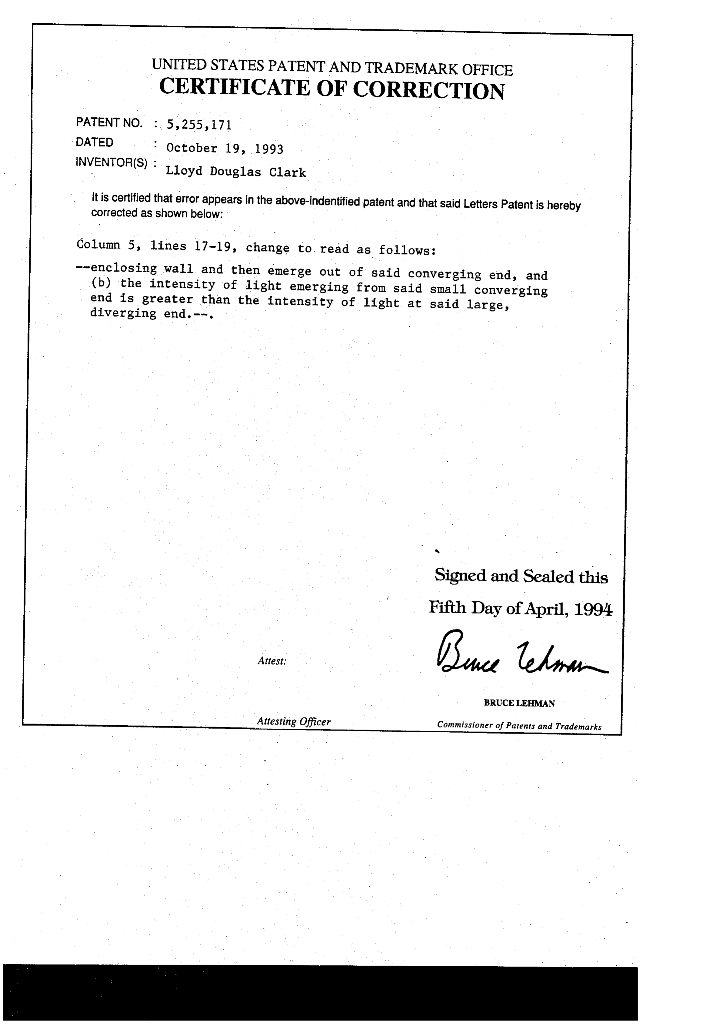
UNITED STATES PATENT ANDTRADEMARK OFFICE
CERTIFICATE OF CORRECTION
INVENTOR(S) Lloyd Douglas Clark it is certified that error appears in the above-indentified patent and that said Letters corrected as shown below: - Patent is hereby
Column 5, lines l7-19, change to read as follows:
--enclosing wall and then emerge out of said converging end, and (b) the intensity of light emerging from said small converging end is greater than the intensity of light at said large, diverging end. --.
Signed and Sealed this
Fifth Day of April, 1994
BRUCELEHMAN
Attesting Officer Commissioner of Patents and Trademarks
Provenance
- Collection
- Cited prior art
- Original PDF
- patentimages.storage.googleapis.com →
- Filed
- 1991-11-27
- Pages
- 10
- Method
- pdftotext (the PDF's own text layer) + pdftoppm 300dpi page scans
- Source
- Google Patents bibliographic record
- Granted
- 1993-10-19
- Inventors
- L. Douglas Clark
- Transcribed from
- patentimages.storage.googleapis.com →