patent · US5325271
Marker lamp with LED array and prismatic diffuser
28 June 1994
Page 1 — bibliographic record
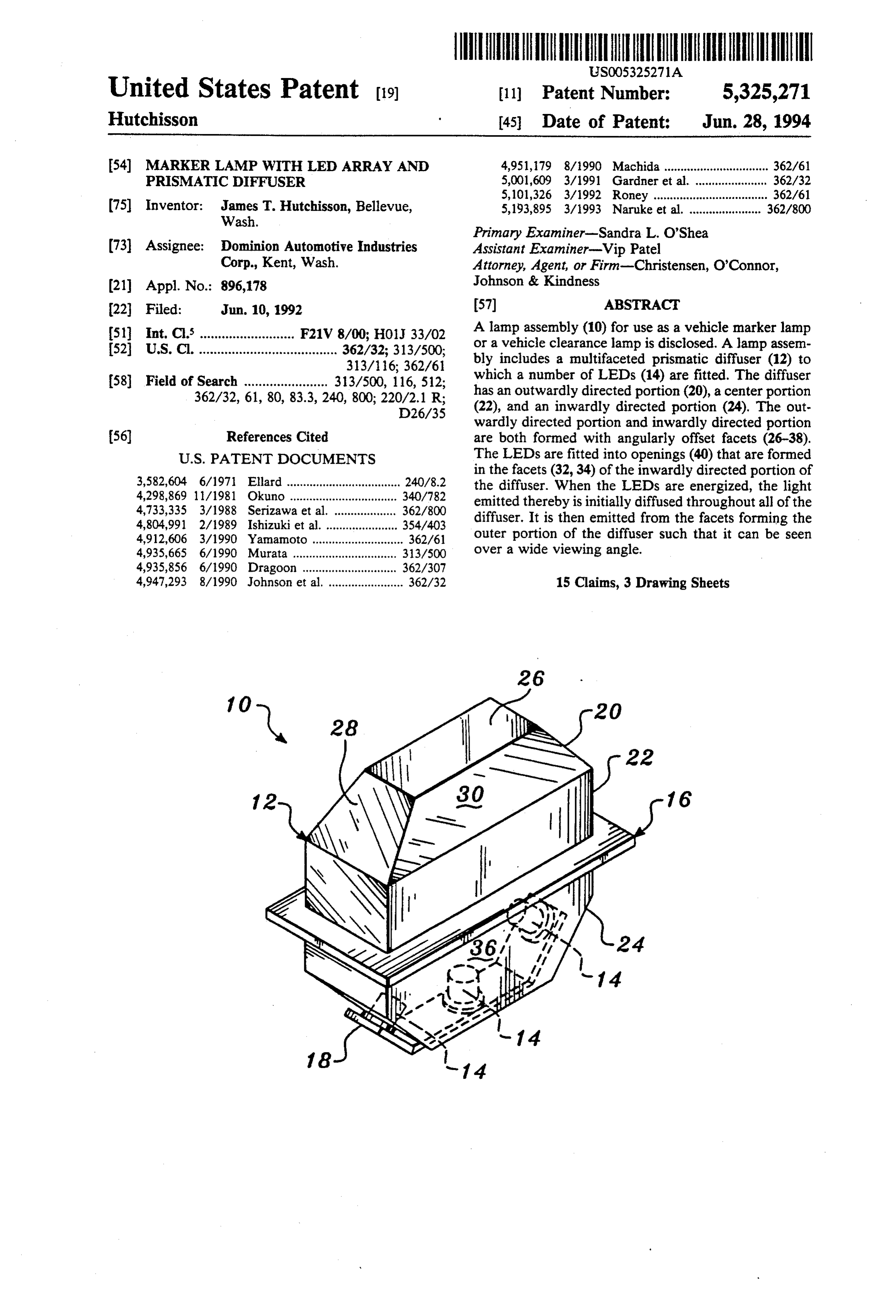
United States Patent (19) 11) Patent Number: 5,325,271 Hutchisson 45 Date of Patent: Jun. 28, 1994 54) MARKER LAMP WITH LED ARRAY AND 4,951,179 8/1990 Machida ................................ 362/61 PRISMATIC OFFUSER ::
Wis A2, Sir et alm
(75) Inventor: ins T. Hutchisson, Bellevue, 5,193,895 3/1993 Naruke et al. ...................... 362/800 ash. Primary Examiner-Sandra L. O'Shea (73 Assignee: Dominion Automotive Industries Assistant Examiner-Vip Patel Corp., Kent, Wash. Attorney, Agent, or Firm-Christensen, O'Connor, (21) Appl. No.: 896,178 Johnson & Kindness 22 Filed: Jun. 10, 1992 57) ABSTRACT 51 Int, C.5 F21V 8/00; H01J 33/02 A lamp assembly (10) for use as a vehicle marker lamp 52 U s Ci 8 a 8 d 4 uous so so a a saw 362/32. 313/500; or a vehicle clearance lamp is disclosed. A lamp assem Ohvo was veu so a was a so a sae as pses no so saw seasoo a 313/16. 362/61 bly includes a multifaceted prismatic diffuser (12) to (58) Field of Search 313/500 11 6, 512: which a number of LEDs (14) are fitted. The diffuser 362/32 61.30,833.240, 800; 320V3 1. R. has an outwardly directed portion (20), a center portion was wws wave rus y 9. b26/35 (22), and an inwardly directed portion (24). The out wardly directed portion and inwardly directed portion (56) References Cited are both formed with angularly offset facets (26-38).
pening (40) that are formed
DOCUMEN in the facets (32, 34) of the inwardly directed portion of
E. .., 3. Ea. w8 a u & w w w w w w w as w w a E.i the diffuser. When the LEDs are energized, the light saw uno ............................... emitted thereby is initially diffused throughout all of the E. As Ea. was a was a w8 as w w w ow :: diffuser. It is then emitted from the facets forming the 6266 5/66 .27 outer portion of the diffuser such that it can be seen 4,935,665 6/1990 Murata ................................ 337so over a wide viewing angle.
4,935,856 6/1990 Dragoon ............................. 362/307 4,947,293 8/1990 Johnson et al. ....................... 362/32 15 Claims, 3 Drawing Sheets
Page 2
Drawing sheet — no readable text.
Page 3
Drawing sheet — no readable text.
Page 4
Drawing sheet — no readable text.
Page 5
conventional incandescent bulb-type marker lamps. A
MARKER LAMP WITH LED ARRAY AND disadvantage of these assemblies is that a single LED PRISMATIC DIFFUSER does not emit light over a relatively wide arc. In order to provide an LED marker lamp assembly capable of
FIELD OF THE INVENTION emitting light over a wide viewing field, it has been This invention relates generally to lamp assemblies necessary to construct these assemblies using a number and, more particularly, to a marker lamp constructed of of spaced-apart LEDs. These assemblies are typically light-emitting diodes. too large to put in a vehicle body opening that are nor mally formed to accommodate marker lights. More
BACKGROUND OF THE INVENTION 10 over, the large number of LEDs that form a single lamp Marker lamps are frequently fitted to the outside of assembly collectively typically consume a relatively large vehicles, such as trucks, trailers, and recreational large amount of power.
vehicles. Marker lamps are installed on a vehicle to SUMMARY OF THE INVENTION provide an indication of its size, shape, and direction of 15 motion so that nearby motorists and pedestrians can This invention relates to a lamp assembly that is well quickly evaluate the characteristics of the vehicle and suited for use as a vehicle marker lamp or a vehicle take necessary steps to avoid an accident. Some vehi clearance lamp. The lamp assembly of this invention cles, such as large trailers, are provided with a set of top includes a prismatic diffuser that is illuminated by a set located marker lights, known as clearance lights. Clear of light-emitting diodes (LEDs). The prismatic diffuser ance lights are mounted on a vehicle in order to provide 20 of this lamp assembly has a number of inwardly directed a ready indication of whether or not the vehicle can facets that are located on the portion of the diffuser that drive under a low ceiling structure, such as a bridge or is mounted to the body to which the lamp assembly is a loading dock canopy. A typical marker lamp assembly attached. The prismatic diffuser also has a set of out comprises an incandescent light bulb that is encased wardly directed facets. These facets are the exposed inside a small housing. A colored lens, typically an 25 surfaces of the lamp assembly. The LEDs are mounted amber lens, forms the outer wall of the housing. The in the inwardly directed facets, so that there is at least amber wavelength light emitted by the bulb passes one LED mounted in two separate facets.
through and is diffused by the lens. This light is the light nearby motorists and pedestrians observe when they see tionWhen are the LEDs of the lamp assembly of this inven energized, the light emitted thereby is initially an illuminated marker light. 30 diffused
While conventional bulb-in-housing marker lamps ted from the assembly throughout the diffuser. The light is then emit have proved useful for providing an indication of the directed diffuser's facets,through so that the various outwardly it can readily be seen shape of the vehicle to which they are attached, they over a relatively wide viewing area.
are not without some limitations. The trucks, trailers, and other vehicles to which these lamps are mounted 35 notThe LEDs of the lamp assembly of this invention do often experience intense vibrations and/or vibrate con prone to any have fragile filaments or other members that are fracture when exposed to prolonged or ex stantly while in motion. The bulbs in these lamp assem blies contain thin, fragile filaments. Over time, the vi treme mechanical vibration. This makes the lamp as brations to which these bulbs are exposed cause the sembly well suited for installation on a trailer or other vehicle as a marker light or a clearance light. The pris filaments to break, resulting in burnout of the bulb. matic diffuser of this assembly collects ambient light Since many marker lamps are located on the top of the and vehicle to which they are attached, and can be 10 or Consequently, reflects the light back to the outside environment. more feet off the ground, removing and replacing the in bright, sunny environments the light is burned-out bulbs can be a laborious and time-consum emitted by this lamp assembly and is not appreciably ing task. Another disadvantage of these assemblies is 45 washed out. Moreover, the prismatic diffuser of this that in some environments the ambient light may be so The lamp assembly is formed from a solid section of plastic. intense that it washes out the light emitted by a marker diffuser thus has a relatively high degree of me-. light. This can make it difficult on a bright, sunny day, chanical strength that allows it to withstand being for example, to use the marker lights to evaluate struck by rocks and other foreign objects. Still another whether there is sufficient clearance for a truck trailer 50 advantage of the lamp assembly of this invention is that, to pass under a bridge or through a tunnel. in comparison to other LED-type lamp assemblies, it Moreover, the housing forming the body of a marker requires fewer LEDs to emit light over the same view lamp is simply a hollow body. The outer wall of this ing field.
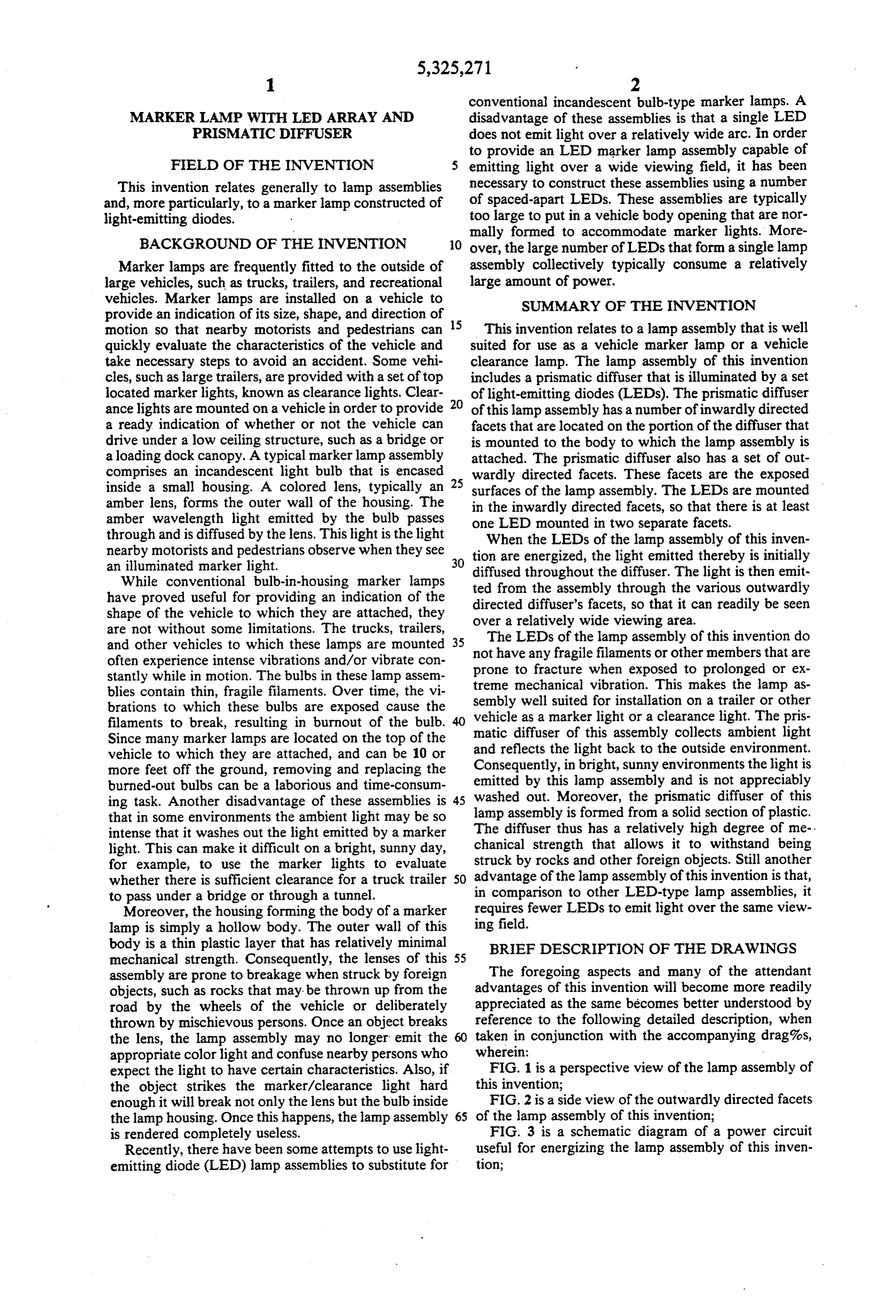
body is a thin plastic layer that has relatively minimal BRIEF DESCRIPTION OF THE DRAWINGS mechanical strength. Consequently, the lenses of this 55 assembly are prone to breakage when struck by foreign The foregoing aspects and many of the attendant objects, such as rocks that may be thrown up from the advantages of this invention will become more readily road by the wheels of the vehicle or deliberately appreciated as the same becomes better understood by thrown by mischievous persons. Once an object breaks reference to the following detailed description, when the lens, the lamp assembly may no longer emit the 60 taken in conjunction with the accompanying drag%s, appropriate color light and confuse nearby persons who wherein:
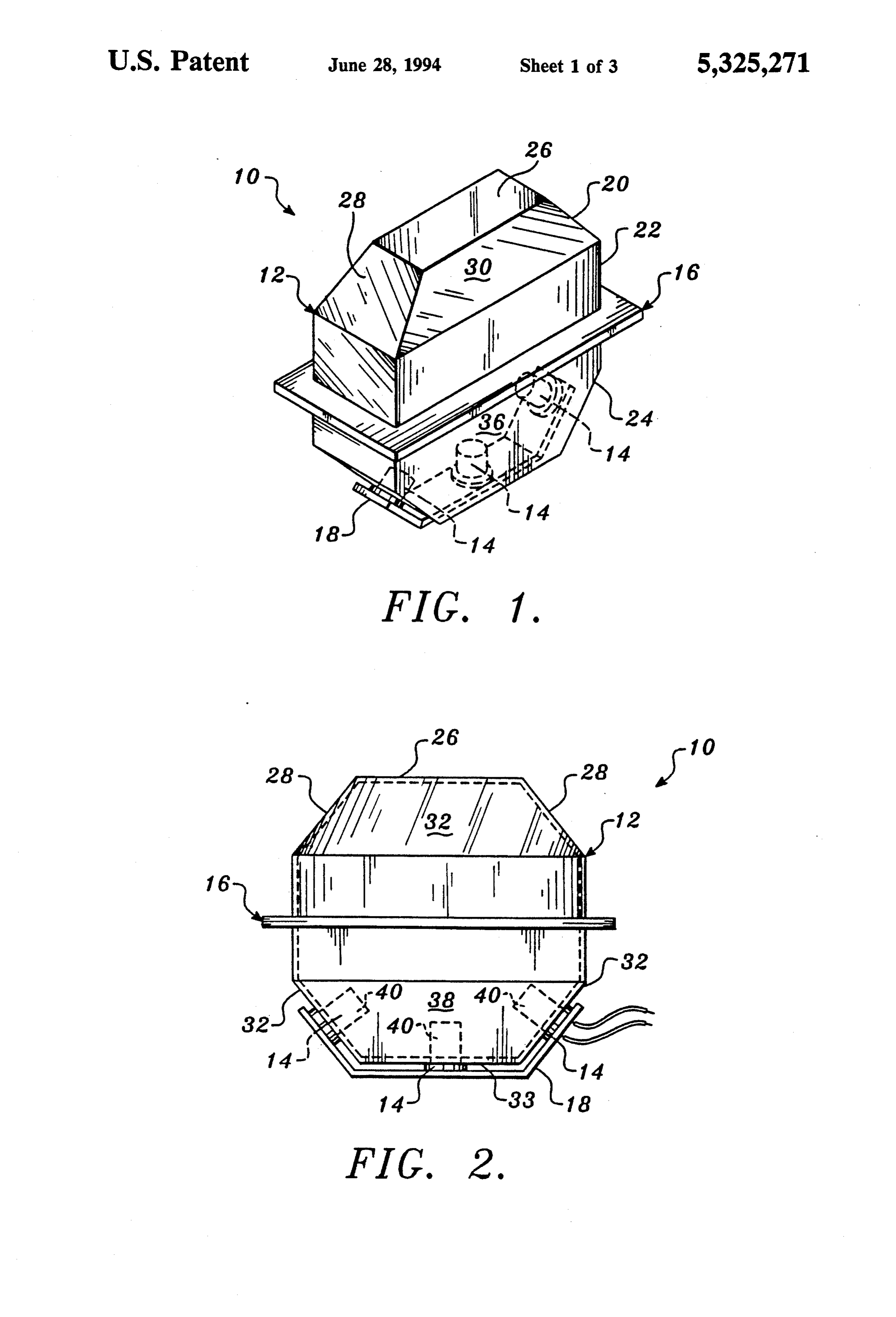
expect the light to have certain characteristics. Also, if FIG. 1 is a perspective view of the lamp assembly of the object strikes the marker/clearance light hard this invention;
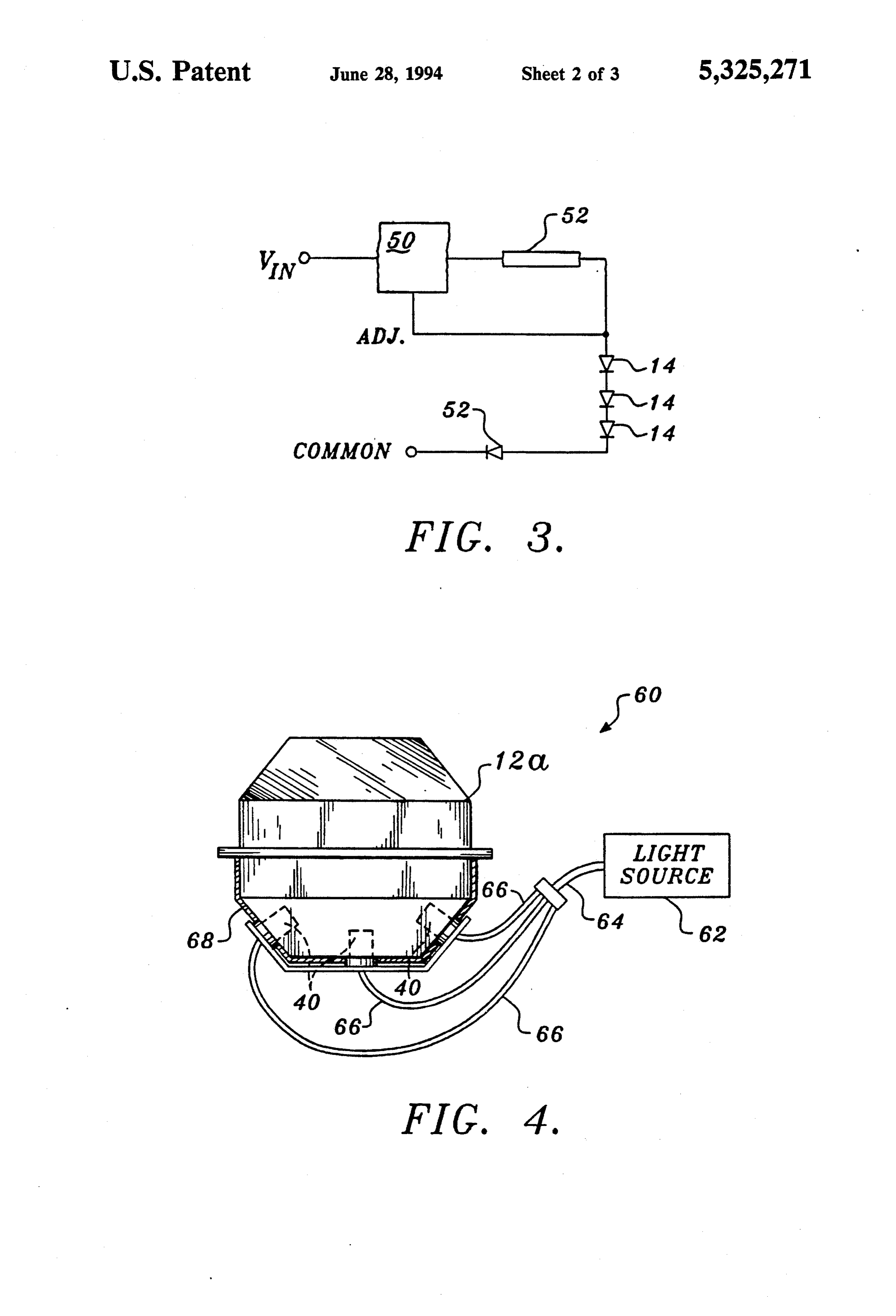
enough it will break not only the lens but the bulb inside FIG. 2 is a side view of the outwardly directed facets the lamp housing. Once this happens, the lamp assembly 65 of the lamp assembly of this invention; is rendered completely useless. FIG. 3 is a schematic diagram of a power circuit Recently, there have been some attempts to use light useful for energizing the lamp assembly of this inven emitting diode (LED) lamp assemblies to substitute for tion;
Page 6
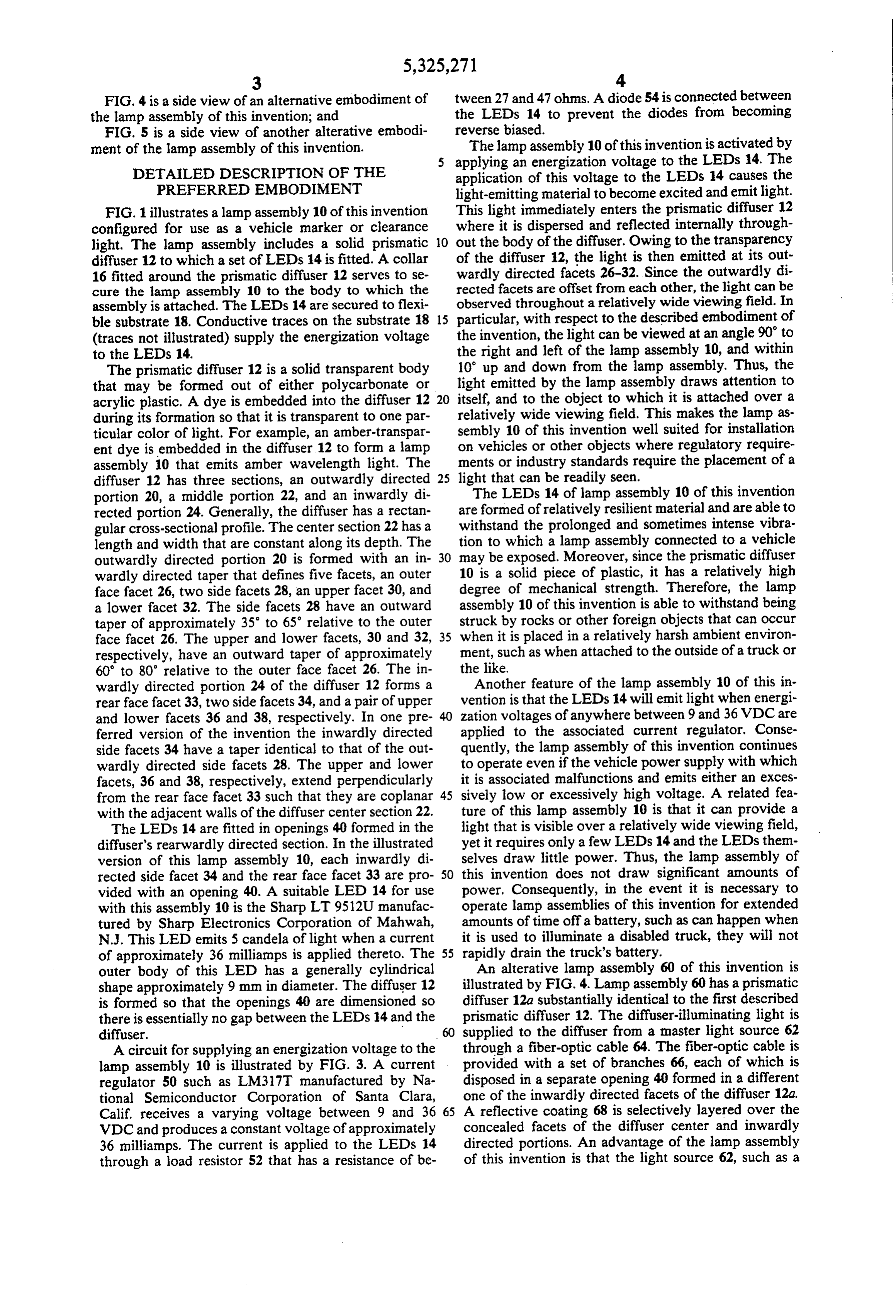
FIG. 4 is a side view of an alternative embodiment of tween 27 and 47 ohms. A diode 54 is connected between the lamp assembly of this invention; and the LEDs 14 to prevent the diodes from becoming FIG. 5 is a side view of another alterative embodi reverse biased.
ment of the lamp assembly of this invention. The lamp assembly 10 of this invention is activated by applying an energization voltage to the LEDs 14. The
DETALED DESCRIPTION OF THE application of this voltage to the LEDs 14 causes the PREFERRED EMBODIMENT light-emitting material to become excited and emit light. FIG. 1 illustrates a lamp assembly 10 of this invention This light immediately enters the prismatic diffuser 12 configured for use as a vehicle marker or clearance where it is dispersed and reflected internally through light. The lamp assembly includes a solid prismatic 10 out the body of the diffuser. Owing to the transparency diffuser 12 to which a set of LEDs 14 is fitted. A collar of the diffuser 12, the light is then emitted at its out 16 fitted around the prismatic diffuser 12 serves to se wardly directed facets 26-32. Since the outwardly di cure the lamp assembly 10 to the body to which the rected facets are offset from each other, the light can be assembly is attached. The LEDs 14 are secured to flexi observed throughout a relatively wide viewing field. In ble substrate 18. Conductive traces on the substrate 18 15 particular, with respect to the described embodiment of (traces not illustrated) supply the energization voltage the invention, the light can be viewed at an angle 90' to to the LEDs 14. the right and left of the lamp assembly 10, and within The prismatic diffuser 12 is a solid transparent body 10' up and down from the lamp assembly. Thus, the that may be formed out of either polycarbonate or light emitted by the lamp assembly draws attention to acrylic plastic. A dye is embedded into the diffuser 12 20 itself, and to the object to which it is attached over a during its formation so that it is transparent to one par relatively wide viewing field. This makes the lamp as ticular color of light. For example, an amber-transpar sembly 10 of this invention well suited for installation ent dye is embedded in the diffuser 12 to form a lamp on vehicles or other objects where regulatory require assembly 10 that emits amber wavelength light. The ments or industry standards require the placement of a diffuser 12 has three sections, an outwardly directed 25 light that can be readily seen.
portion 20, a middle portion 22, and an inwardly di The LEDs 14 of lamp assembly 10 of this invention rected portion 24. Generally, the diffuser has a rectan are formed of relatively resilient material and are able to gular cross-sectional profile. The center section 22 has a withstand the prolonged and sometimes intense vibra length and width that are constant along its depth. The tion to which a lamp assembly connected to a vehicle outwardly directed portion 20 is formed with an in 30 may be exposed. Moreover, since the prismatic diffuser wardly directed taper that defines five facets, an outer 10 is a solid piece of plastic, it has a relatively high face facet 26, two side facets 28, an upper facet 30, and degree of mechanical strength. Therefore, the lamp a lower facet 32. The side facets 28 have an outward assembly 10 of this invention is able to withstand being taper of approximately 35 to 65° relative to the outer struck by rocks or other foreign objects that can occur face facet 26. The upper and lower facets, 30 and 32, 35 when it is placed in a relatively harsh ambient environ respectively, have an outward taper of approximately ment, such as when attached to the outside of a truck or 60 to 80 relative to the outer face facet 26. The in the like.
wardly directed portion 24 of the diffuser 12 forms a Another feature of the lamp assembly 10 of this in rear face facet 33, two side facets 34, and a pair of upper vention is that the LEDs 14 will emit light when energi and lower facets 36 and 38, respectively. In one pre zation voltages of anywhere between 9 and 36 VDC are ferred version of the invention the inwardly directed applied to the associated current regulator. Conse side facets 34 have a taper identical to that of the out quently, the lamp assembly of this invention continues wardly directed side facets 28. The upper and lower to operate even if the vehicle power supply with which facets, 36 and 38, respectively, extend perpendicularly it is associated malfunctions and emits either an exces from the rear face facet 33 such that they are coplanar 45 sively low or excessively high voltage. A related fea with the adjacent walls of the diffuser center section 22. ture of this lamp assembly 10 is that it can provide a The LEDs 14 are fitted in openings 40 formed in the light that is visible over a relatively wide viewing field, diffuser's rearwardly directed section. In the illustrated yet it requires only a few LEDs 14 and the LEDs them version of this lamp assembly 10, each inwardly di selves draw little power. Thus, the lamp assembly of rected side facet 34 and the rear face facet 33 are pro 50 this invention does not draw significant amounts of vided with an opening 40. A suitable LED 14 for use power. Consequently, in the event it is necessary to with this assembly 10 is the Sharp LT9512U manufac operate lamp assemblies of this invention for extended tured by Sharp Electronics Corporation of Mahwah, amounts of time off a battery, such as can happen when N.J. This LED emits 5 candela of light when a current it is used to illuminate a disabled truck, they will not of approximately 36 milliamps is applied thereto. The 55 rapidly drain the truck's battery. outer body of this LED has a generally cylindrical An alterative lamp assembly 60 of this invention is shape approximately 9 mm in diameter. The diffuser 12 illustrated by FIG. 4. Lamp assembly 60 has a prismatic is formed so that the openings 40 are dimensioned so diffuser 12a substantially identical to the first described there is essentially no gap between the LEDs 14 and the prismatic diffuser 12. The diffuser-illuminating light is diffuser. supplied to the diffuser from a master light source 62 A circuit for supplying an energization voltage to the through a fiber-optic cable 64. The fiber-optic cable is lamp assembly 10 is illustrated by FIG. 3. A current provided with a set of branches 66, each of which is regulator 50 such as LM317T manufactured by Na disposed in a separate opening 40 formed in a different tional Semiconductor Corporation of Santa Clara, one of the inwardly directed facets of the diffuser 12a, Calif. receives a varying voltage between 9 and 36 65 A reflective coating 68 is selectively layered over the VDC and produces a constant voltage of approximately concealed facets of the diffuser center and inwardly 36 milliamps. The current is applied to the LEDs 14 directed portions. An advantage of the lamp assembly through a load resistor 52 that has a resistance of be of this invention is that the light source 62, such as a
Page 7
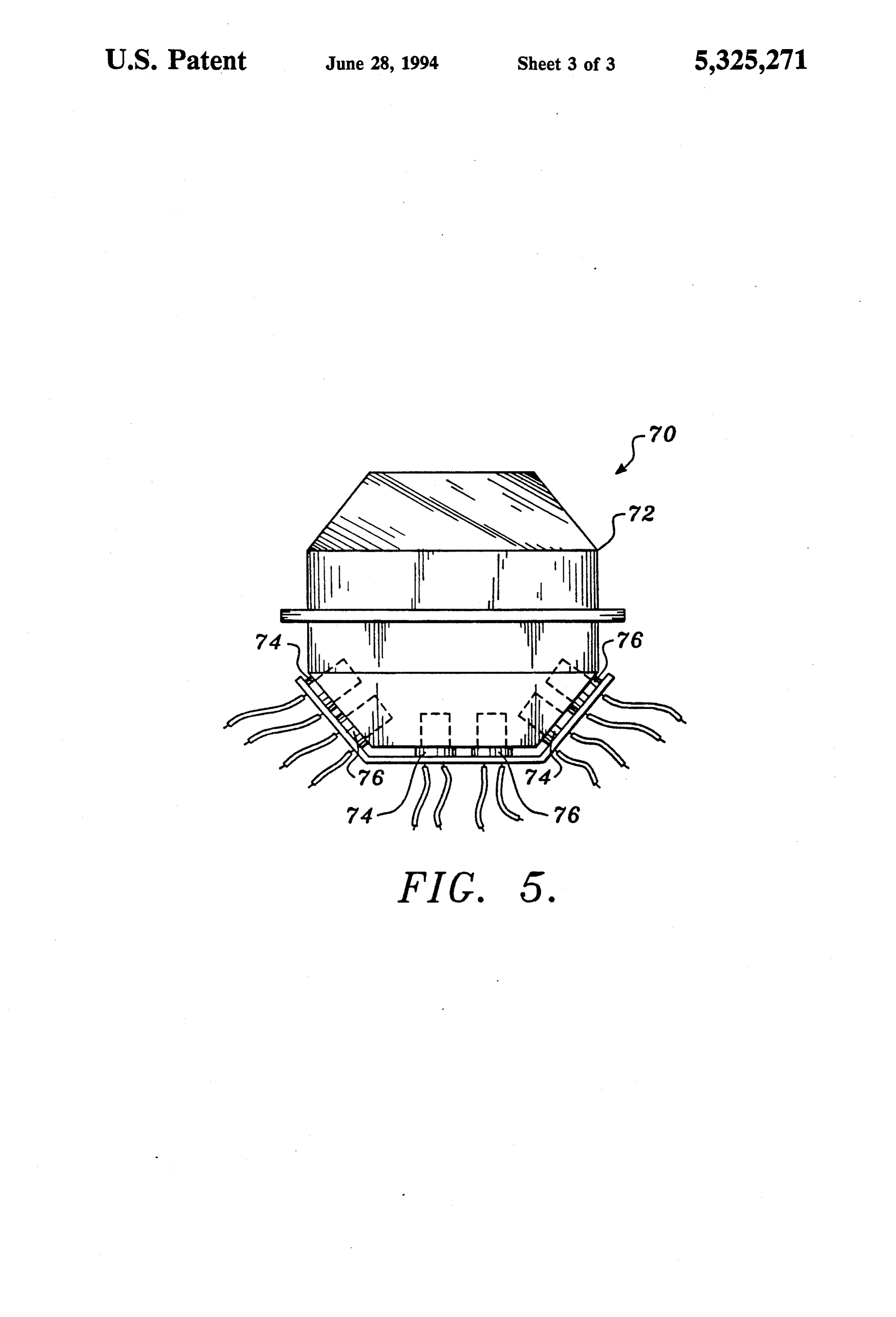
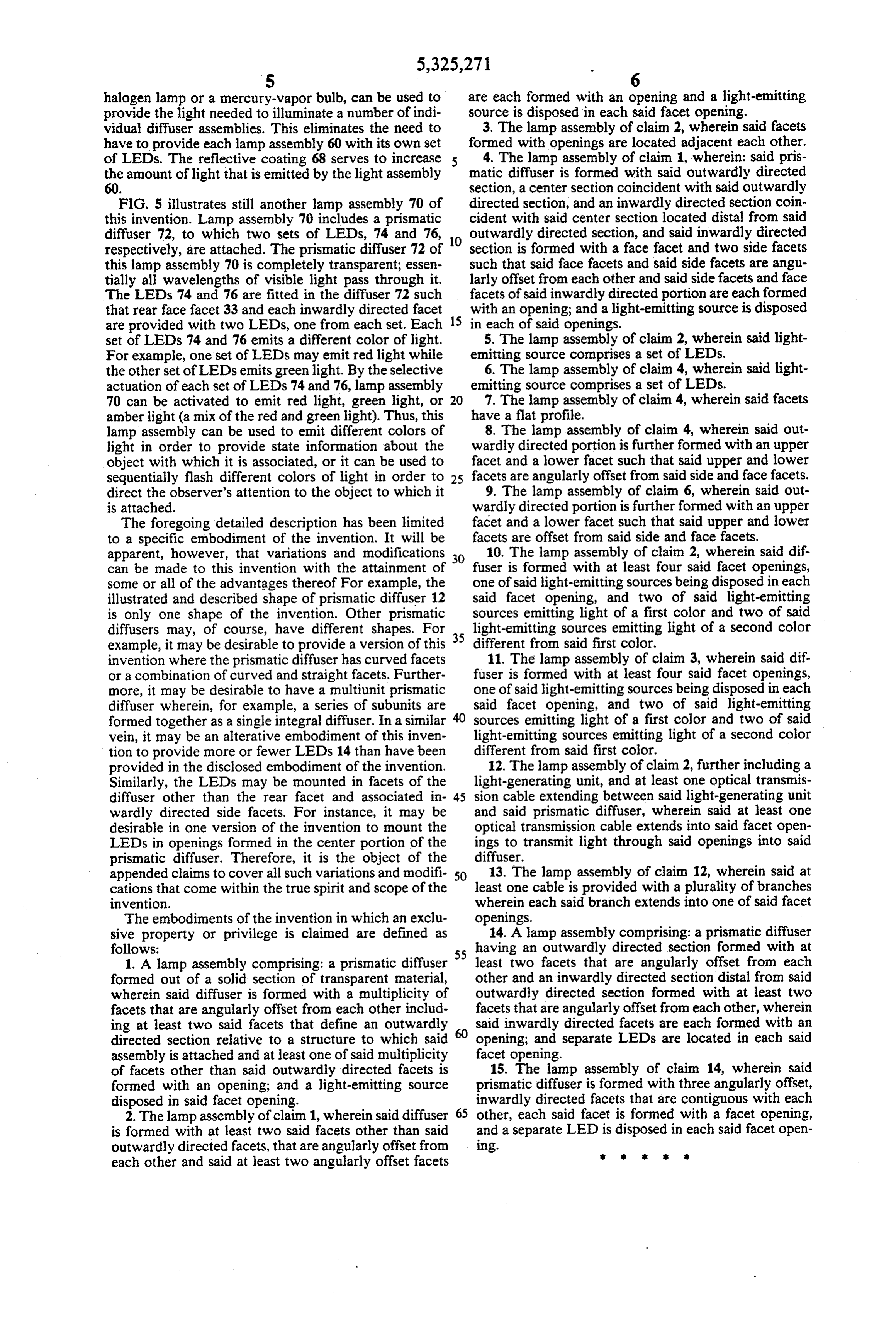
halogen lamp or a mercury-vapor bulb, can be used to are each formed with an opening and a light-emitting provide the light needed to illuminate a number of indi source is disposed in each said facet opening. vidual diffuser assemblies. This eliminates the need to 3. The lamp assembly of claim 2, wherein said facets have to provide each lamp assembly 60 with its own set formed with openings are located adjacent each other. of LEDs. The reflective coating 68 serves to increase 4. The lamp assembly of claim 1, wherein: said pris the amount of light that is emitted by the light assembly matic diffuser is formed with said outwardly directed 60. section, a centersection coincident with said outwardly FIG. 5 illustrates still another lamp assembly 70 of directed section, and an inwardly directed section coin this invention. Lamp assembly 70 includes a prismatic cident with said center section located distal from said diffuser 72, to which two sets of LEDs, 74 and 76, outwardly directed section, and said inwardly directed respectively, are attached. The prismatic diffuser 72 of 10 section is formed with a face facet and two side facets this lamp assembly 70 is completely transparent; essen such that said face facets and said side facets are angu tially all wavelengths of visible light pass through it. larly offset from each other and said side facets and face The LEDs 74 and 76 are fitted in the diffuser 72 such facets of said inwardly directed portion are each formed that rear face facet 33 and each inwardly directed facet 15 with an opening; and a light-emitting source is disposed are provided with two LEDs, one from each set. Each in each of said openings.
set of LEDs 74 and 76 emits a different color of light. 5. The lamp assembly of claim 2, wherein said light For example, one set of LEDs may emit red light while emitting source comprises a set of LEDs. the other set of LEDs emits green light. By the selective 6. The lamp assembly of claim 4, wherein said light actuation of each set of LEDs 74 and 76, lamp assembly emitting source comprises a set of LEDs. 70 can be activated to emit red light, green light, or 20 7. The lamp assembly of claim 4, wherein said facets amberlight (a mix of the red and green light). Thus, this have a flat profile.
lamp assembly can be used to emit different colors of 8. The lamp assembly of claim 4, wherein said out light in order to provide state information about the wardly directed portion is further formed with an upper object with which it is associated, or it can be used to facet and a lower facet such that said upper and lower sequentially flash different colors of light in order to 25 facets are angularly offset from said side and face facets. direct the observer's attention to the object to which it 9. The lamp assembly of claim 6, wherein said out is attached. wardly directed portion is further formed with an upper The foregoing detailed description has been limited facet and a lower facet such that said upper and lower to a specific embodiment of the invention. It will be facets are offset from said side and face facets. apparent, however, that variations and modifications 30 10. The lamp assembly of claim 2, wherein said dif can be made to this invention with the attainment of fuser is formed with at least four said facet openings, some or all of the advantages thereof For example, the one of said light-emitting sources being disposed in each illustrated and described shape of prismatic diffuser 12 said facet opening, and two of said light-emitting is only one shape of the invention. Other prismatic sources emitting light of a first color and two of said diffusers may, of course, have different shapes. For 35 light-emitting sources emitting light of a second color example, it may be desirable to provide a version of this different from said first color.
invention where the prismatic diffuser has curved facets 11. The lamp assembly of claim 3, wherein said dif. or a combination of curved and straight facets. Further fuser is formed with at least four said facet openings, more, it may be desirable to have a multiunit prismatic one of said light-emitting sources being disposed in each diffuser wherein, for example, a series of subunits are said facet opening, and two of said light-emitting formed together as a single integral diffuser. In a similar sources emitting light of a first color and two of said vein, it may be an alterative embodiment of this inven light-emitting sources emitting light of a second color tion to provide more or fewer LEDs 14 than have been different from said first color.
provided in the disclosed embodiment of the invention. 12. The lamp assembly of claim 2, further including a Similarly, the LEDs may be mounted in facets of the light-generating unit, and at least one optical transmis diffuser other than the rear facet and associated in 45 sion cable extending between said light-generating unit wardly directed side facets. For instance, it may be and said prismatic diffuser, wherein said at least one desirable in one version of the invention to mount the optical transmission cable extends into said facet open LEDs in openings formed in the center portion of the ings to transmit light through said openings into said prismatic diffuser. Therefore, it is the object of the diffuser.
appended claims to cover all such variations and modifi 50 13. The lamp assembly of claim 12, wherein said at cations that come within the true spirit and scope of the least one cable is provided with a plurality of branches invention. wherein each said branch extends into one of said facet The embodiments of the invention in which an exclu openings.
sive property or privilege is claimed are defined as 14. A lamp assembly comprising: a prismatic diffuser follows: having an outwardly directed section formed with at 1. A lamp assembly comprising: a prismatic diffuser 55 least two facets that are angularly offset from each formed out of a solid section of transparent material, other and an inwardly directed section distal from said wherein said diffuser is formed with a multiplicity of outwardly directed section formed with at least two facets that are angularly offset from each other includ facets that are angularly offset from each other, wherein ing at least two said facets that define an outwardly said inwardly directed facets are each formed with an directed section relative to a structure to which said opening; and separate LEDs are located in each said assembly is attached and at least one of said multiplicity facet opening.
of facets other than said outwardly directed facets is 15. The lamp assembly of claim 14, wherein said formed with an opening; and a light-emitting source prismatic diffuser is formed with three angularly offset, disposed in said facet opening. inwardly directed facets that are contiguous with each 2. The lamp assembly of claim 1, wherein said diffuser 65 other, each said facet is formed with a facet opening, is formed with at least two said facets other than said and a separate LED is disposed in each said facet open outwardly directed facets, that are angularly offset from ing. s sk each other and said at least two angularly offset facets
Page 8
UNITED STATES PATENT ANDTRADEMARK OFFICE
CERTIFICATE OF CORRECTION
INVENTOR(S) : J.T. Hutchisson it is certified that error appears in the above-indentified patent and that said Letters Patent is hereby Corrected as shown below:
2 60 "drag%s," should read-drawings.- 5 32 "thereof For" should read-thereof. For
Signed and Sealed this
Fourth Day of October, 1994
(a teen
BRUCELEMAN
Attesting Officer Commissioner of Patents and Trademarks
Provenance
- Collection
- Cited prior art
- Original PDF
- patentimages.storage.googleapis.com →
- Filed
- 1992-06-10
- Pages
- 8
- Method
- pdftotext (the PDF's own text layer) + pdftoppm 300dpi page scans
- Source
- Google Patents bibliographic record
- Granted
- 1994-06-28
- Inventors
- James T. Hutchisson; Dominion Automotive Industries Corp
- Transcribed from
- patentimages.storage.googleapis.com →