patent · US5140220
Light diffusion type light emitting diode
18 August 1992
Page 1 — bibliographic record
United States Patent (19) 11 Patent Number: 5,140,220 Hasegawa (45) Date of Patent: Aug. 18, 1992 (54) LIGHT DIFFUSION TYPE LIGHTEMITTING 3,875,456 4/1975 Kano et al. ......................... 33/501 DODE 3,900,863 8/1975 Kinn ....................................... 357/17 4,168,102 9/1979 Chida et al.......................... 313/512 75) Inventor: Yasuo Hasegawa, Shiga, Japan 4,191,943 3/1980 Cairns et al... 340/815.01 4,195,330 3/1980 Savage, Jr. .......................... 362/226 73 Assignees: Yumi Sakai; Masakatsu Uchiyama, 4,415,604 1/1983 Nativi ............ 525/455 X both of Kyoto, Japan 4,521,835 6/1985 Meggs et al. ....................... 362/83 21 Appl. No.: 240,416 4,603,496 8/1986 Latz et al. ....................... 313/500 X 22) Fied: Sep. 1, 1988 OTHER PUBLICATIONS
Visible Light-Emitting Diode by IBM, Authors Jaco
Related U.S. Application Data bus, Jr. and Stuby, vol. 10, #8, 1968, p. 1120.
63 Continuation of Ser. No. 936,831, Dec. 2, 1986, aban Optical Crystals, by Optovac, 1982, pp. 5-1-5-4. doned.
Primary Examiner-Donald J. Yusko 30) Foreign Application Priority Data Assistant Examiner-Michael Horabik
Dec. 2, 1985 JP Japan ........................... 60-186493U Attorney, Agent, or Firm-Price, Gess & Ubell 51) int. Cl. ................................................ HO1J 5/16 57 ABSTRACT 52 U.S. C. .................................... 313/512; 313/116; An improved light emitting diode housing member 313/499; 362/329; 362/800; 340/815.17 comprises a transparent housing that can extend over 58) Field of Search ............... 313/110, 116, 499, 500, the light emitting surface of the LED and can position 313/501, 512; 340/815.01, 815.15, 815.17; a plurality of granular optical particles, such as calcium
fluoride, over the source of light to provide a diffusion 56) References Cited of the emitted light, thereby increasing its viewing an
3,653,959 4/1972 Kehr et al. ........................ 357/72 X 12 Claims, 1 Drawing Sheet
Page 2
Drawing sheet — no readable text.
Page 3
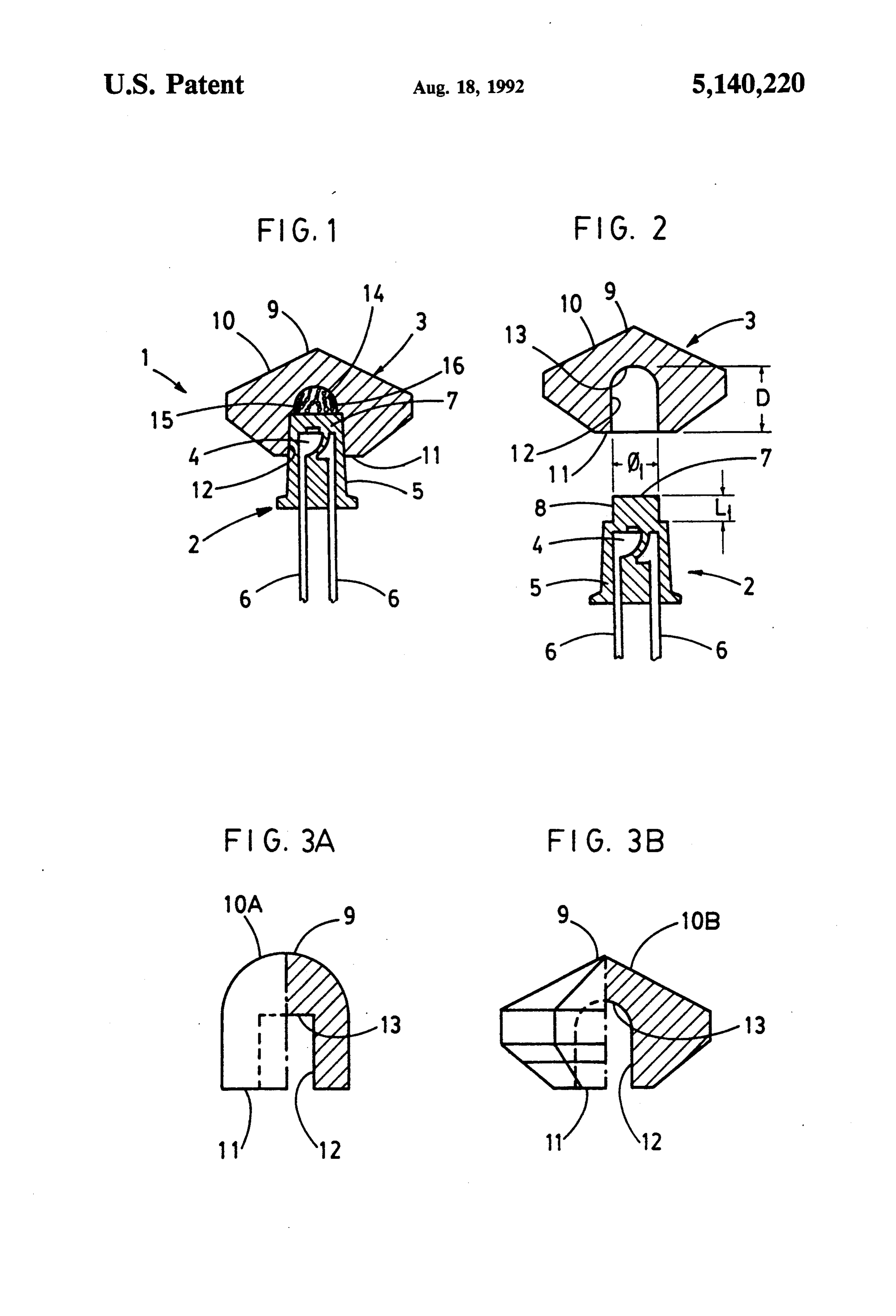
FIG. 2 is an exploded sectional elevation view of
LIGHT OFFUSON TYPE LIGHT EMITTING another form of the coupled portion between a light DODE emitting diode invention and a light diffusing member. FIGS. 3A and 3B are side views, half in cross section,
This is a continuation of application Ser. No. 936,831 5 of different forms of the light diffusing member. filed on Dec. 2, 1986 now abandoned. (1) . . . Light diffusion type light emitting diode unit (2) . . . Light emitting diode invention
BACKGROUND OF INVENTION (3) . . . Light diffusing member 1. Technical Field (7) . . . Light emitting end
The present invention relates to improvements in 10 (8) . . . Connecting portion photoelectric transfer devices such as light emitting (12) . .. .. Coupling (10). Light diffusedly-radiated surface hole diode (LED) devices, in which a light emitting semi conductor pellet is monolithically molded in the inner (15) . . . Space room portion thereof, particularly to light diffusion type light 15 (16) ... Transparent grains emitting diode units having light diffusing means at its DESCRIPTION OF INVENTION light-diffusing end. Now the present invention will be described in detail 2. Prior Art
It is well known that light emitting diodes are photoe followingtoexamples:
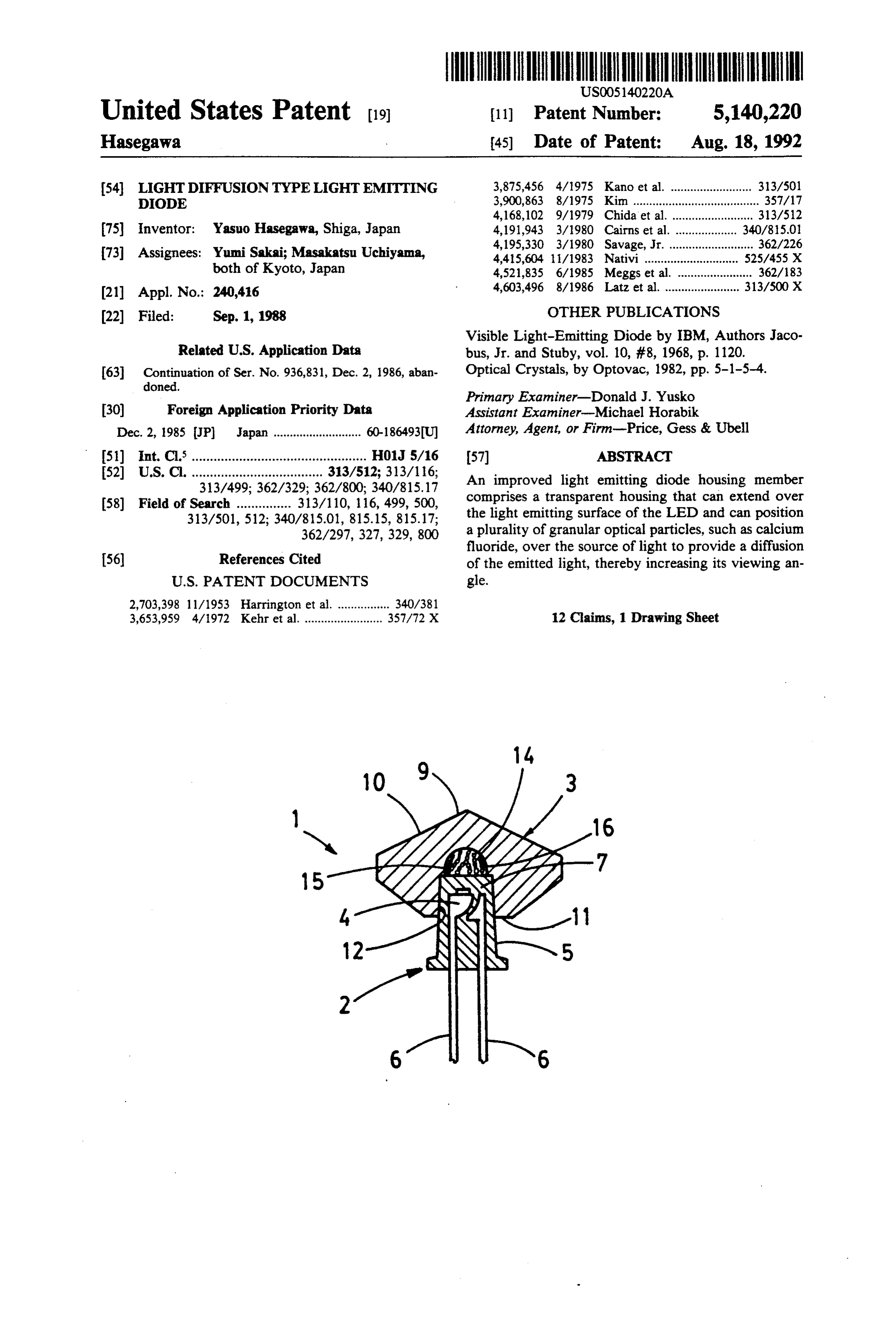
referring the drawings, and in connection with the lectric transfer devices which transmit light energy A light diffusion type light emitting diode unit 1 of converted from electrical energy, and are extensively the present invention comprises in its essential portion a employed as electronic circuit components which oper light emitting diode device 2 and a light diffusing mem ate effectively at lower voltages. The light emitting ber 3, both being coupled to each other. Said light emit diode is a device in which a semiconductor pellet is ting diode device 2 is fabricated by monolithically monolithically moided using highly transparent plastic 25 molding a semiconductor pellet portion 4 using a highly material, with its light emitting end being configured to transparent plastic material 5, such as acrylic resins, and serve as lens for enhanced directivity of radiated out includes a pair of lead portions 6 at one end and a light put. However, recent expansion of the semiconductor radiating end 7 at the other end. Said light radiating end crystal growth techniques has led to marked improve 7 in said light emitting device 2 need not have a lens-like ment in light emission efficiency; and hence, to design 30 configuration for enhanced directivity, but, as seen in said light emitting diode devices so as to allow light to the accompanying drawings, may be constructed to radiate in a wider angle without controlling the light in form a coupling portion 8 having an outer diameter di any specific direction, rather than to cause the light to and a length L1, which is to be fitted into the light closely follow a specified direction, results in expanded diffusing member 3 to be described subsequently. On applications of the present invention, thus making it 35 the other hand, said light diffusing member 3 is molded more advantageous. into various configurations with highly transparent plastics such as acrylic composite resins, as typically
OBJECT OF INVENTION represented by FIGS. 3A and 3B. In any of the exam Accordingly, it is the object of the present invention ples cited above, said light diffusing member has a light to provide a light diffusion type light emitting diode diffusedly-radiated surface 10 at one end, and a cou unit having an exceedingly simple structure in which a pling hole 12 at the other end. Said light diffusedly light diffusing means is provided at the light radiating radiated surface 10 is defined as spherical surface 10A as end of the light emitting device to form an integral unit, indicated in FIG. 3A, in one example, and as cut surface and offering higher efficiency in diffused radiation of 5 10, in another example, which is diamond-cut into a multifaceted configuration, as depicted in FIG. 3B. Said light.
coupling hole 12 extends from the end of the light dif
SUMMARY OF INVENTION fusing member 3 to said light diffusedly-radiated surface 10 and ends at a bottom wall 13. The depth D of said
Specifically, the present invention relates to a light coupling hole 12 is greater than the length L1 of the diffusion type light emitting diode comprising, for at 50 coupling portion with said light emitting diode device 2; taining the foregoing object, a light emitting diode de alternatively, a concave vice having the light emitting end capable of control can be provided in the portion 14 of reduced diameter ling the direction of outgoing rays, and a transparent pling hole 12 on the sidebottom of said surface 13 of the cou light diffusing member light diffusing member having a light diffusedly 3 so that the depth of insertion into said coupling hole radiated surface at one end, and at the other end a cou 55 12 equivalent to the length L1 of the coupling portion of pling hole which extends from said other end to said the light emitting diode device 2. In either case, it is surface and has its innermost portion formed as a granu acceptable as long as the coupling hole 12 is designed so lar housing; placing, gluing or planting grains in the that a space room 15 is created when the light emitting granular housing in said light diffusing member; and so end coupling portion 8 in said light emitting diode de constructed as to couple the light emitting end of said vice 2 is fitted into the coupling hole 12 of said light light emitting diode device to said grains through the diffusing member. Into said space room 15 there are coupling hole provided in said light emitting member, placed, glued or planted transparent grains 16 for light so that they face each other. diffusion before the said coupling hole 12 and the cou BRIEF DESCRIPTION OF THE DRAWINGS 65 pling portion of the light emitting diode device 2 are fitted together to form a coupling. Said grains 16 are
FIG. 1 is a sectional side elevation view of the basic made of, for example, a single-crystal material of cal structure of a light diffusion type light emitting diode cium fluoride (CaF2). Preferably, said grains 16 possess unit of the present invention; high transparency and refractive index, and are of the
Page 4
order of 20 to 30 mesh. Said grains 16 are placed, glued 7. An improved light diffusing light emitting diode or planted into the space room 15 in said light diffusing assembly comprising:
member 3. The grains can, for example, be "potted" by a light emitting base member having a light emitting adding methylene chloride to allow the wall of said device mounted in a transparent plastic housing space room 15 composed of acrylic resin to dissolve member, the base member including a light radiat itself, thereby locking the grains 16. ing end member and a coupling portion extending The light diffusion type light emitting diode unit adjacent to and around the light radiating end relating to the present invention and having the above member on the plastic housing member; mentioned construction provides a light diffusing means a light diffusing member of a hemispherical hollow in the light radiating portion of the light emitting diode, O core configuration is dimensioned to interface with thus making it possible to design a light emitting diode and is fixed to the coupling portion, and capable of effectively diffusing outgoing radiation, and a plurality of granular optical particles positioned also of checking for the light emitting diode being prop within the hollow core and extending between the erly lit from various angles. Accordingly, the light dif. light radiating end member and the light diffusing fusion type light emitting diode of the present invention 15 member, the granular optical particles having air is widely applicable and highly effective as accompany exposed surfaces within the hollow core of the ing light emitting device for indicator lamps in adver diffusing member for reflecting and refracting light tisement devices, signs and other equipment, and also projecting from the light radiating end and also for store decoration and display devices. having particle surfaces adhering to the housing Having described our invention as related to the ex 20 member to stationarily fix the optical particles. amples shown in the accompanying drawings, it is our 8. The diode assembly of claim 7 wherein the granu intention that the invention be not limited by any of the lar particles are calcium fluoride. details of description, unless otherwise specified, but 9. The diode assembly of claim 7 wherein the granu rather be construed broadly within its spirit and scope lar particles are approximately 20 to 30 mesh in particle as set out in the claims. 25 Sze.
What is claimed is: 10. The diode assembly of claim 7 wherein an exterior 1. An improved light diffusing light emitting diode envelope of the diffusing member has a multifaceted assembly comprising: configuration.
a light emitting device with a light radiating end 11. An improved light diffusing light emitting diode capable of controlling the direction of a radiated 30 assembly consisting of:
output of light; a single light emitting device with a transparent light a transparent hollow housing member mounted on radiating end positioned above the light emitting the light emitting device and extending over the device and capable of controlling the direction of a light radiating end, and radiated output of light;
a plurality of granular optical particles positioned 35 a coupling portion integrally positioned on the light within the transparent hollow housing member and radiating end;
extending between the light radiating end and the a transparent hollow housing member mounted on housing member, the granular optical particles the coupling portion of the light emitting device having exposed surfaces within the hollow portion and extending over the light radiating end, an exte of the housing member for reflecting and refracting rior surface of the housing member has a multifac light from the light radiating end and also having eted configuration, and particle surfaces adhering to the housing member a plurality of granular optical particles of approxi to stationarily fix those optical particles, whereby a mately 20 to 30 mesh in particles size are positioned diffusion of light can be accomplished. within the transparent hollow housing member and 2. The diode assembly of claim 1 wherein the granu 45 extend between the light radiating end and the lar particles are formed of calcium fluoride. housing member, the granular optical particles 3. The diode assembly of claim 1 wherein the granu having air exposed surfaces within the hollow por lar particles are approximately 20 to 30 mesh in particle tion of the housing member for reflecting and re SZe. fracting light from the light radiating end and 4. The diode assembly of claim 1 wherein the granu 50 some, but not all of the particles also having a lar particles are potted in methylene chloride within the portion of their particle surfaces adhering to the housing member. housing member to stationarily fix those optical 5. The diode assembly of claim 1 wherein the housing particles, whereby a diffusion of light can be ac member has a plurality of planar facets. complished.
6. The diode assembly of claim 4 wherein the granu 55 12. The diode assembly of claim 11 wherein the gran lar particles are formed of calcium fluoride and are ular particles are embedded into an interior surface of secured by methylene chloride within the housing the hollow housing member. k k k k k member.
Provenance
- Collection
- Cited prior art
- Original PDF
- patentimages.storage.googleapis.com →
- Filed
- 1988-09-01
- Pages
- 4
- Method
- pdftotext (the PDF's own text layer) + pdftoppm 300dpi page scans
- Source
- Google Patents bibliographic record
- Granted
- 1992-08-18
- Inventors
- Yasuo Hasegawa
- Transcribed from
- patentimages.storage.googleapis.com →