patent · US5567037
LED for interfacing and connecting to conductive substrates
22 October 1996
Page 1 — bibliographic record
United States Patent (19) 11) Patent Number: 5,567,037 Ferber (45) Date of Patent: Oct. 22, 1996 (54) LED FOR INTERFACING AND 5,113,325 5/1992 Eisenbraun .............................. 362/103 CONNECTING TO CONDUCTIVE 5,140,220 8/1992 Hasegawa ... ... 362/800 SUBSTRATES 5,160,200 11/1992 Cheselske .... ... 362,249 5,253,149 10/1993 Ostema et al. ... 362/104 (75) Inventor: Andrew R. Ferber, New York, N.Y. 5,278,734 1/1994 Ferber ...... ... 362,103 5,296,782 3/1994 Sawaii....... ... 313f499 (73) Assignee: Ferber Technologies, L.L.C., Roseland, 5,440,461 8/1995 Nadel et al. ............................ 362/103 N.J. Primary Examiner-Denise L. Gromada
Assistant Examiner-Sara Sachie Raab (21) Appl. No.: 434,370 Attorney, Agent, or Firm-Lerner, David, Littenberg, Krum holz & Mentlik (22 Filed: May 3, 1995 57) ABSTRACT
52 U.S. Cl. .......................... 362/104; 362/249; 362/800; An illumination device for enhancing the structural and 362/806; 63/1.1; 24/101 R; 2/905 aesthetic appearance of associated articles or substrates and (58) Field of Search ..................................... 362/103, 104, to provide operative coaction with conductive current paths 362/249, 800, 806; 2/243.1, 905; 313/512, made from conductive paints, inks and the like compositions on such articles and substrates is disclosed. The illumination 110; 63/1.1, 2, 26, 32; 24/101 R, 102 P. device comprises an LED having leads, the LED and at least
one portion of the leads are encapsulated within a substan 56 References Cited tially nonconductive relatively transparent or translucent housing. At least a second portion of the leads of the LED
3,609,475 9/1971 Kaposhillin .......................... 317,234 R flush along an exterior surface of the housing so that when 3,812,406 5/1974 Henri ......... 317/235 N the housing is connected by suitable connectors to the 4,047,075 9/1977 Schoberl ................................. 313/500 associated article or substrate, electrical communication 4,774,642 9/1988 Janko et al. 362A103 with an external power source can be established for oper 4.942,744 7/1990 Wei............................................ 63/1. ating and actuating the LED.
5,018,053 5/1991 Belknap et al. 362/04 5,066,889 11/1991 Edwards .................................. 313/52 19 Claims, 5 Drawing Sheets
Page 2
Drawing sheet — no readable text.
Page 3
Drawing sheet — no readable text.
Page 4
Drawing sheet — no readable text.
Page 5
Drawing sheet — no readable text.
Page 6
Drawing sheet — no readable text.
Page 7
LED FOR INTERFACING AND dolls, accessories for dolls or other accessories on which an CONNECTING TO CONDUCTIVE LED module may be affixed for decorative purposes. SUBSTRATES The present invention solves all of these shortcomings in the prior art and particularly provides an improved LED module encapsulated within a housing and which is intended
FIELD OF THE INVENTION to be secured, affixed or adhered to various types of apparel The present invention relates to light emitting diodes to create a design on or enhance the appearance of apparel, (LEDs). More particularly, the present invention relates to or to toys, dolls and other devices. LED modules disposed for providing illuminated decora SUMMARY AND OBJECTS OF THE tions, designs or assemblies on appare such as wearing 10 INVENTION apparel, decorative apparel, toys, clothing for dolls or acces sories and operatively associated with conductive paints, According to one aspect of the present invention, an inks and the like type of compositions on such articles for illumination device comprises an LED having a diode body and a pair of leads connected to the diode body. Each of the transmitting electrical current for the operation and actuation 15 leads of such LED modules. includes a first portion extending along a first plane away from the diode body. Encapsulating material is pro vided which forms a housing which completely surrounds
BACKGROUND OF THE INVENTION the diode body and defines external walls having predeter mined boundaries such that the first portion of the leads
The use of LED modules for decorating various articles, 20 extends along the first plane and through at least one of the such as wearing apparel or accessories, is well known in the external walls formed by the encapsulating material. Each of apparel industry. Such LED modules are also connected to the leads also includes a second portion which extends many types of articles, the structure of the LED modules and outside of the housing along a second plane generally the means for connecting the LED modules to an associated transverse to the respective first portion of the leads so as to article varies depending upon the structure of the article to 25 lie substantially flush against the external wall of the hous which the LED modules are affixed and the means for ing through which the first portion extends. The second conducting the current for operating and actuating Such LED portion of the leads preferably terminates at a location modules. within the boundary defined by the external wall along Although the prior art discloses LED modules that are which the respective second portion of the leads extends. connected to various types of articles such as clothing, 30 Preferably, the respective second portion of the leads footwear, sunglasses, etc. and to electrical circuitry thereon begins at a location after the associated first portion of the generally utilizing hard wire conductors for operating and leads exits the housing. In one preferred embodiment, the actuating the LED modules, there is no teaching or sugges second portion of the leads extends substantially to the tion as to how to affix LED modules to electrically conduc boundary of the external wall. tive paths, such as conductive paint, arranged on the asso 35 The encapsulating housing of the illumination device may ciated apparel, footwear, toys, etc. comprise various shapes and sizes. In a preferred embodi U.S. Pat. No. 5,278,734 discloses a creative structure ment, the housing includes facets thereon which act to which utilizes cooperating threads to attach LED modules to enclose the diode body of the LED within a jewel-like various articles including wearing apparel such as Sweat casing.
shirts and the like. 40
The illumination device may also comprise a connector
The prior art also discloses encapsulated LEDs for various means for affixing the housing to a given piece of apparel or purposes. For example, U.S. Pat. No. 5,018,053 discloses a other substrate. The connector means may comprise a coact partially encapsulated LED within a non-conductive ing socket for removably engaging the housing with the enamel-like material for use as jewelry. U.S. Pat. No. 45 apparel or other substrate to which the housing is being 3,812,406 discloses a crystal on which a large number of affixed. Alternatively, a suitable connector on the housing electroluminescent diodes are manufactured to display an can extend through the apparel, toy, doll or other substrate alphanumeric letter. The crystal is made of a semi-conductor or device. Any of the connector means for such illuminating material and is protected by a transparent resin. device act to enable the leads on the illumination device to None of the aforementioned patents disclose an LED 50 be brought into operative association with the conductive encapsulated within a housing made of non-conductive paints, inks or the like compositions on the apparel, toys, material wherein the leads of the LED extend outside of the dolls and other devices for delivering the current for oper housing and are bent or formed for placement substantially ating and actuating the encapsulated LED. flush against the housing wall through which they extend. The apparel used in connection with the illumination This arrangement is a significant improvement over known 55 device in accordance with the present invention may com LED modules as it provides a structure suitable for electrical prise wearing apparel, decorative articles, clothing for dolls, connection to conductive paint paths, and other electrically accessories for dolls and humans, etc. The apparel may conductive paths, arranged on an associated article or Sub include a first surface and a second surface and may have Strate.
current conducting means arranged on the first surface for
Further, there is a need in the prior art for providing an 60 transmitting current from a power source to the associated efficient arrangement for connecting an LED module to an LED module or modules as the case may be. In this associated article, such as clothing for humans or dolls or embodiment, the second portion of the leads is arranged other accessories wherein the LED module can be affixed to adjacent to the first surface of the apparel for electrical the apparel in an aesthetically pleasing manner. communication with the current conducting means. The The term apparel as used in the present application is 65 socket may be arranged adjacent the second surface of the intended to encompass various types of articles including apparel in alignment with the housing so that it can be wearing apparel, decorative articles, footwear, clothing for brought into engagement therewith.
Page 8
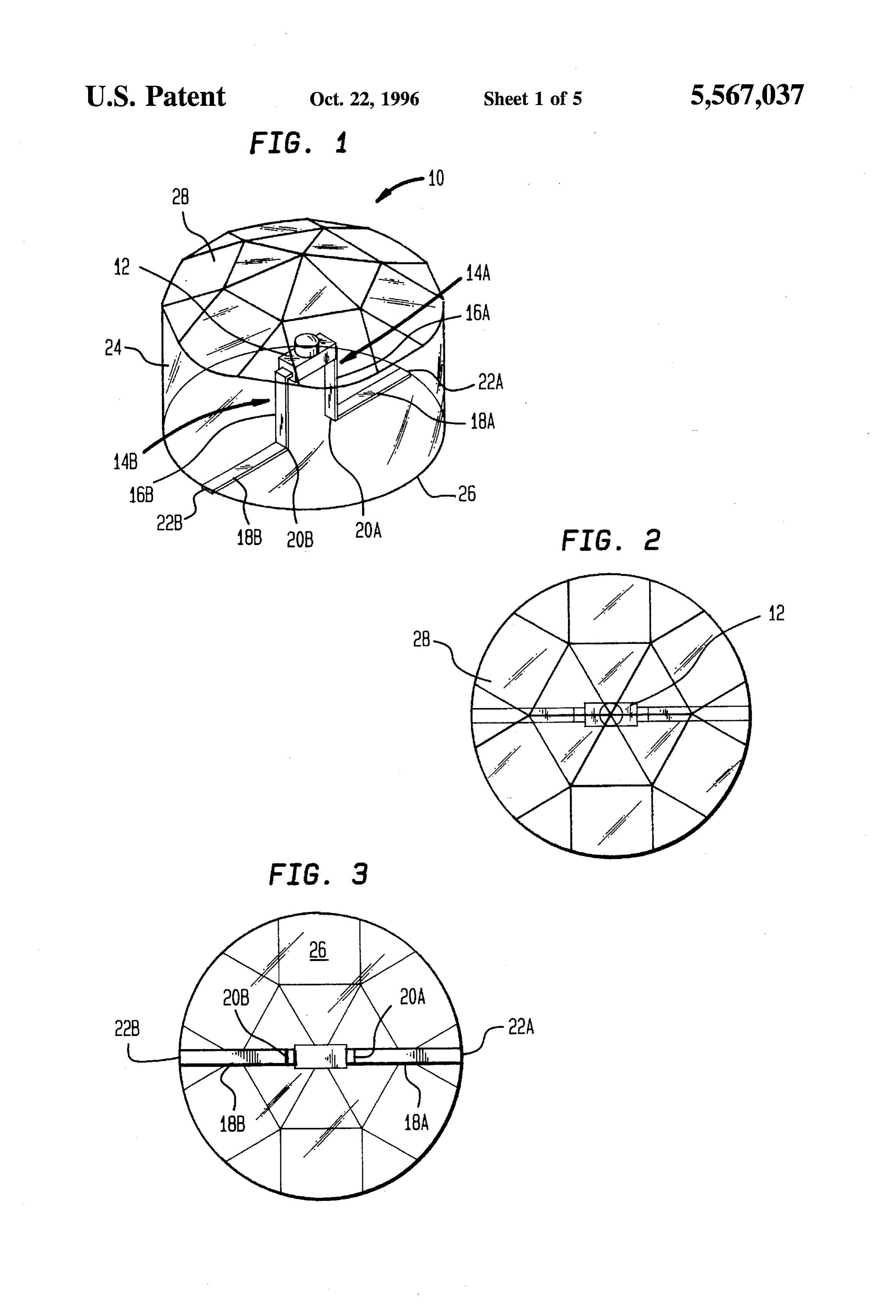
The engagement between the socket and the housing may disposed in electrical communication with the conductive be enhanced by adhering or gluing the housing to the first composition path on the apparel. surface of the apparel and alternately or selectively adhering or gluing the socket to the second surface of the apparel. DETAILED DESCRIPTION OF THE Where the connector means extends through the apparel, 5 PREFERRED EMBODIMENTS toy, doll or other substrate or device, a suitable removable In accordance with one embodiment of the invention, and independent locking means can be provided for engag FIGS. 1, 2 and 3 show an illumination device generally ing and holding each respective LED module or modules in designated 10. The illumination device 10 includes an assembled position, as the case may be.
10 internally arranged diode forming an LED 12 having a pair
The present invention is also directed toward a decorative of conductive leads 14A and 14B.
article of apparel in combination with the illumination Each of the leads 14A and 14B include a first vertically or device discussed above. Preferably, the decorative article of longitudinally extending portion 16A and 16B. The leads apparel includes current conducting path thereon for per 14A and 14B also include a second portion 18A and 18B mitting current to flow from a power source to an associated 15 which extend generally transverse or even substantially LED module. The current conducting path may comprise perpendicular to the vertically extending portions 16A and conductive paint, ink or other conductive compositions. 16B, all of which is shown in FIG. 1 of the. drawings. It may be desirable for the decorative article to include a The LED body 12 and a portion of the leads 14A and 14B switch which controls the flow of current from the power are encapsulated within a housing 24, preferably made of a source to the illumination device of the present invention. 20 non-conductive relatively transparent or translucent mate Various switches or the like devices may be used. Alterna rial. Suitable materials for this purpose are well known in the tively, a human finger, or other body part, may act as a art. Those skilled in the art will recognize that the particular switch when placed across a conductive path so that current material used to form the housing 24 which encapsulates the is momentarily permitted to flow from the associated power LED body 12 and the portion of the leads 14A and 14B is source to the LED module or modules, thus permitting the 25 not critical. Thus, in addition to the materials above illus associated or desired LED module or modules to be momen trated, housing 24 may be made of many different types of tarily and selectively activated. materials that can provide a supporting structure and may be Other objects, features and advantages of the present formed, molded, cast and fabricated to provide a desired invention will be more fully understood with reference to the aesthetically pleasing appearance. following detailed description of the preferred embodiments 30 Preferably, the encapsulating housing material is sufi when taken in conjunction with the accompanying drawings. ciently transparent or translucent to allow light on operation of the LED 12 to be transmitted therethrough. The housing
BRIEF DESCRIPTION OF THE DRAWINGS 24 includes a bottom surface 26, which may be substantially flat. This arrangement will permit sufficient contact to result
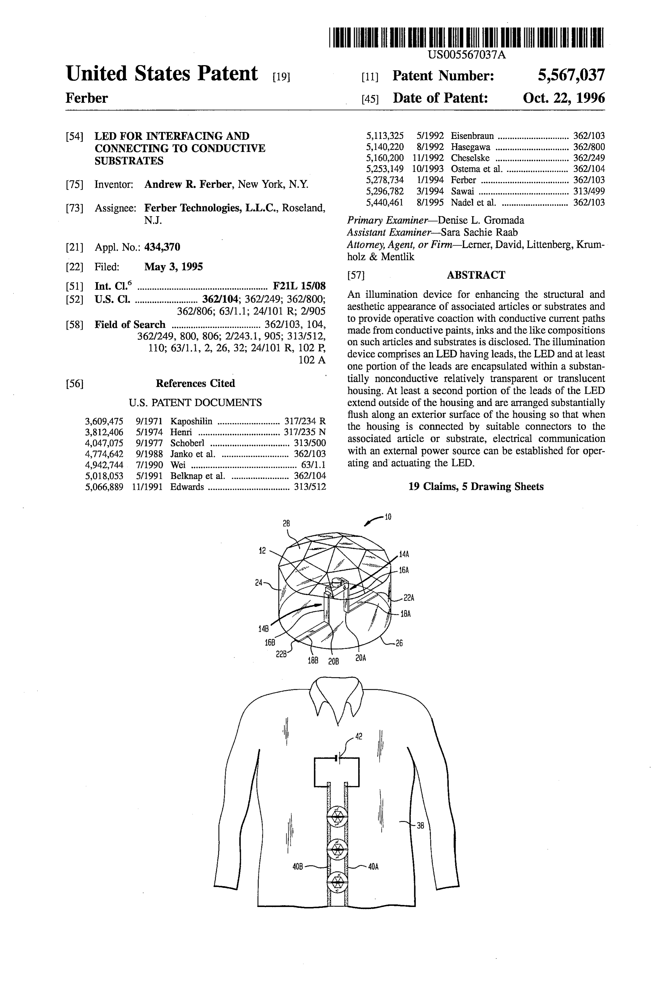
FIG. 1 is a perspective view of an illumination device in 35 between the second portion 18A and 18B of the leads 14A accordance with the present invention. and 14B and the associated conductive paint paths or other FIG. 2 is a top plan view of the illumination device shown materials used to form electrically conductive paths. in FIG. 1.
As further illustrated in FIGS. 1 and 2, the housing 24 also
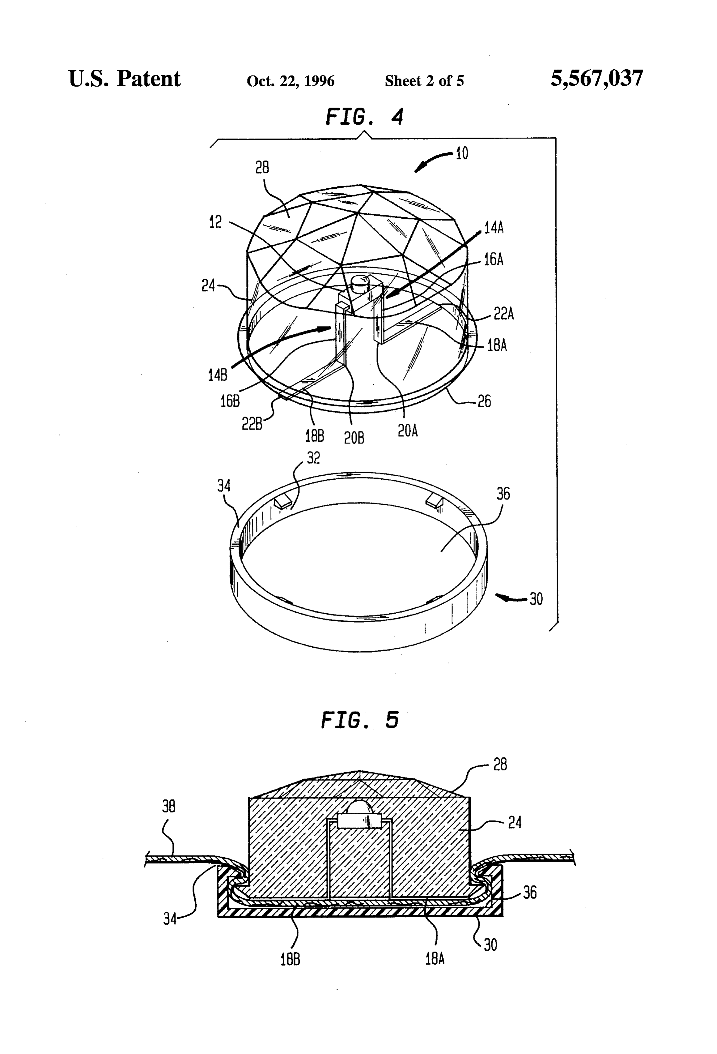
FIG. 3 is a bottom plan view of the illumination device includes a top section 28 which may have a pleasing shown in FIG. 1. 40 ornamental design including facets thereon. The facets may FIG. 4 is an exploded perspective view of a second appear similar to facets which are often cut into gem stones embodiment of an illumination device in accordance with or cosmetic jewelry. This aspect of the present invention will the present invention including one form of connecting provide the illumination device 10 with a creative aesthetic assembly. appearance when it is used to decorate an associated article.
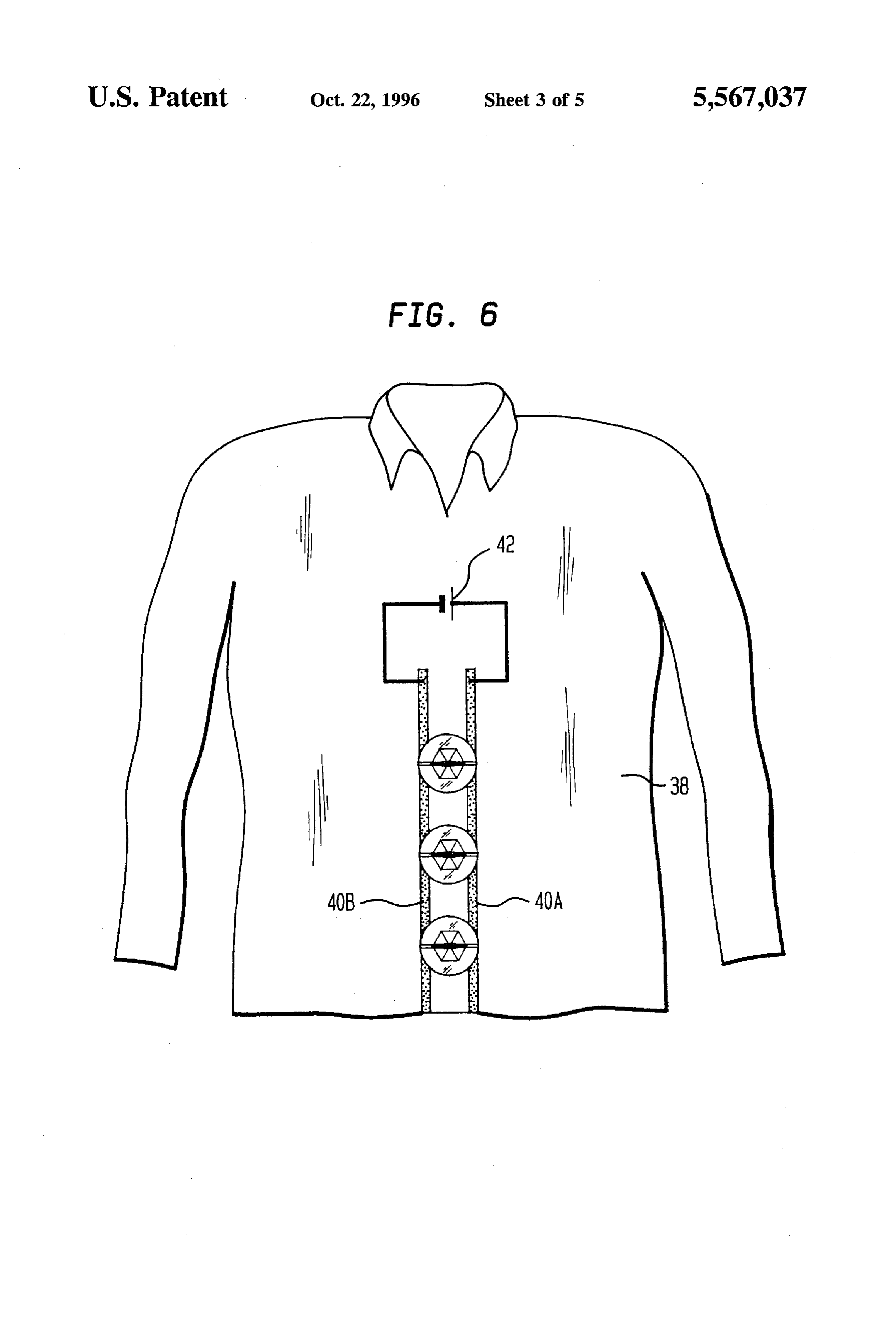
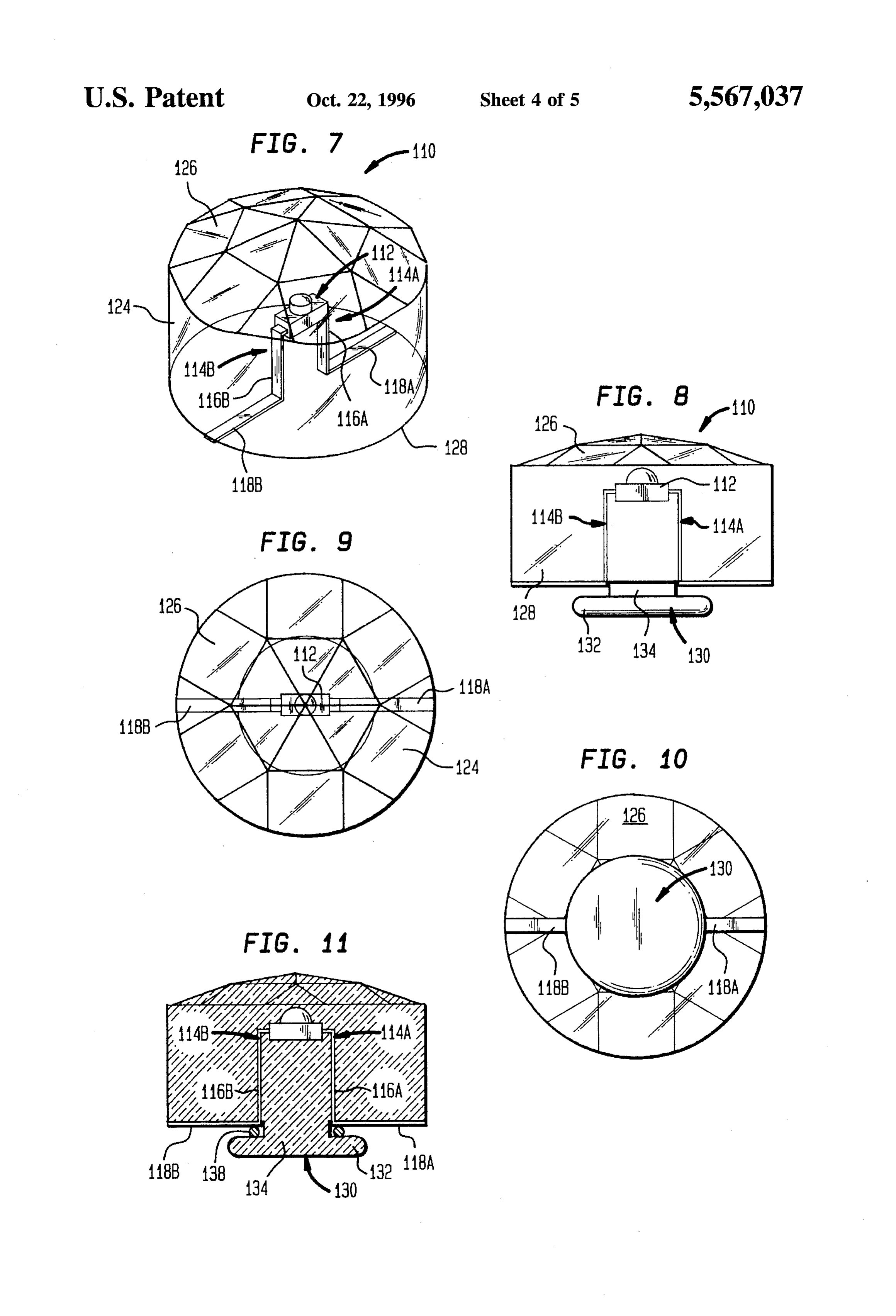
FIG. 5 is a cross-sectional view of the illumination device Referring further to FIGS. 1 and 3, the respective second shown in FIG. 4 in assembled position on an article of portions 18A and 18B of the leads 14A and 14B extend apparel. substantially flush along the external side of the bottom FIG. 6 is a perspective view of the illumination device of surface 26 of housing 24. Although the bottom surface 26 is FIGS. 1 or 4 shown in assembled position on an article of 50 illustrated in FIGS. 1 and 3 as being substantially flat, it may wearing apparel. have alternate shapes without departing from the scope of FIG. 7 is a perspective view of a third embodiment of the the present invention. However, regardless of the shape of illumination device in accordance with the present invention the bottom surface 26, it is important that the respective including another form of connecting assembly. second portion 18A and 18B of the leads 14A and 14B FIG. 8 is a side view of the illumination device shown in 55 extend along the external side of the bottom surface 26 to FIG. 7. establish the necessary electrical communication between the leads 14A and 14B to achieve the desired operation and
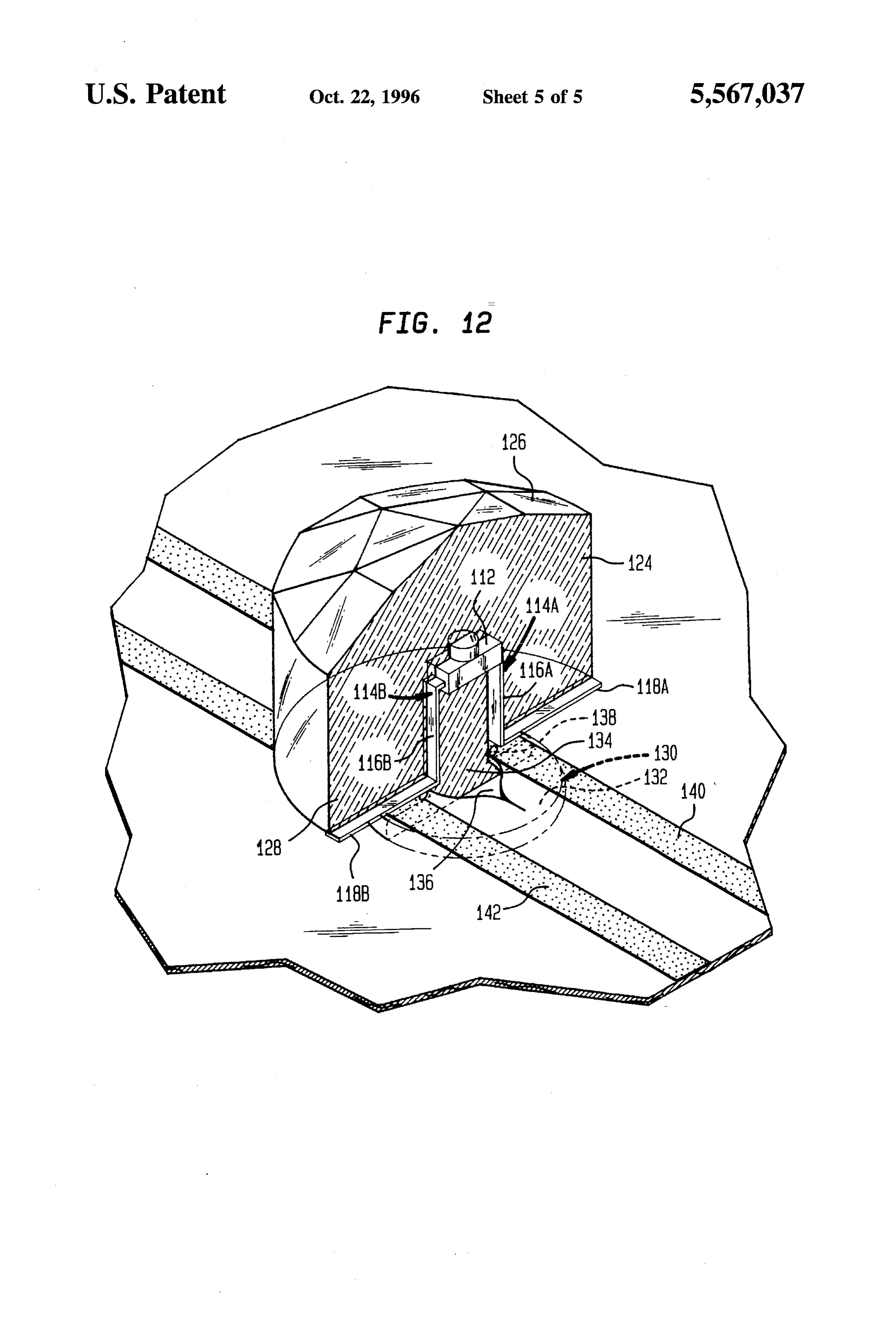
FIG. 9 is a top plan view of the illumination device shown activation of the LED 12 in the illumination device in in FIG. 7. accordance with the present invention. FIG. 10 is a bottom plan view of the illumination device 60 A transitional connecting portion 20A and 20B of the shown in FIG. 7. leads 14A and 14B as shown in FIGS. 1, 3 and 4 exists FIG. 11 is a cross-section taken on line 11-11 of FIG. 9, between the first portion 16A and 16B and the second and portion 18A and 18B at the point where leads 14A and 14B FIG. 12 is an enlarged perspective view partly in vertical emerge from the encapsulating material which forms hous section of the illumination device shown in FIGS. 7 to 11 of 65 ing 24.
these drawings in assembled position on an article of apparel In a preferred embodiment, the second portion of the leads having the externally exposed second portion of the leads 18A and 18B terminates at a location designated 22A and
Page 9
22B substantially adjacent to the outermost or peripheral The conductive paths may include conductive paints, inks or boundary of the bottom surface 26. This aspect of the present the like compositions such as the first and second conductive invention is best shown in FIG. 3. In alternate embodiments, paint paths 40A and 40B shown on a sweatshirt 38 in FIG. the second portion 18A and 18B of the leads 14A and 14B 6. As can be appreciated with reference to FIGS. 5 and 6, the may not extend to the peripheral boundary defined by the substantially flush arrangement of the second portion 18A bottom surface 26. However, it is important that a sufficient and 18B of the leads 14A and 14B with respect to the bottom length of the respective second portion 18A and 18B of the surface 26 of the housing 24 will facilitate electrical con leads 14A and 14B extend along the bottom surface 26 so nection between conductive paint paths 40A and 40B and that electrical contact can be made with electrically conduc the second portion 18A and 18B of the leads. Further, the tive paths arranged on an article or substrate such as an 10 outermost ends 22A and 22B of the second portion 18A and article of apparel, as shown in FIG. 6. 18B of the leads are shown in FIG. 6 as being in electrical FIG. 4 illustrates a second embodiment of the present contact with corresponding first and second conductive paint invention wherein the illumination device 10' includes a paths 40A and 40B. In order to enhance the ornamental sockets-type connector generally designated 30 that may be appearance of the present invention, and to prevent struc used to facilitate connecting the illumination device 10' to 15 tural defects, it is preferable that the outermost ends 22A and the surface of an article, such as clothing for people or dolls 22B of the second portion 18A and 18B of the leads 14A and or accessories therefor. 14B are terminated within the boundaries defined by the Socket 30 is preferably made of a nonconductive material bottom surface 26 of the housing 24.
which will minimize the risk of shorting the illumination The use of conductive paint paths 40A and 40B in device 10 when it is in electrical communication with the combination with LEDs is a novel concept which has many desired current conducting paints, inks and the like compo different practical uses. For purposes of the present inven sitions defining the current conducting paths for operating tion, it is not necessary to consider the current conducting the LED 12 encapsulated in the housing 24. In this regard, capabilities of various types of conductive paints, inks and the socket 30 is preferably made of a plastic material or other the like compositions. However, it should be appreciated material that is compatible with the housing 4. However, if 25 that suitable examples of conductive paints include compo desired, the socket 30 may also be made of a conductive sitions or paints which permit sufficient current to flow material provided that the article to be arranged between the therethrough so that the illumination device 10 can be socket 30 and the second portion 18A and 18B of the leads selectively activated. The conductive paints may include 14A and 14B does not permit current to flow therebetween. different colors and may have a composition that can be As best illustrated in FIGS. 4 and 5, the socket30 includes 30 washed along with an associated article without causing a recessed area 32 designed to receive the housing 24. The degradation of the current carrying capability thereof. recessed area 32 may be sized to accommodate a press fit A If further detailed description of conductive compo engagement with the side walls of the housing 24. A sitions that may be used in connection with the present shoulder 34 is arranged along the boundary of the socket 30 invention, there are is describe more fully) in U.S. Pat. to clearly define the recessed area 32. Optionally, the socket 35 No. 5,455,749 co-pending application U.S. application Ser. 30 may include a bottom surface 36. However, in alternate No. 08/229,359 filed Apr. 15, 1994), the disclosure of which embodiments, the bottom surface 36 may be eliminated and is incorporated by reference herein. the socket 30 may merely comprise an annular ring. In such A power source designated by battery 42 is shown in FIG. embodiments, the annular ring is preferably sized and 6 as being associated with the sweatshirt 38. It may be shaped to accommodate a frictional engagement to the preferable to place the power source 42 in a pocket or on the housing 24 and the article on which the illumination device inner surface of an article of apparel to make the outer 10 is mounted. appearance of the apparel or article as attractive as possible. In the embodiment shown in FIGS. 4 and 5, the shoulder In order to prevent light from being continuously transmitted 34 protrudes further toward the center of the recessed area 45 from the LED 12, the present invention may utilize various 32 than do the side walls of the socket 30. This is another types of LEDs or switches to control when current from the optional feature of the present invention which is designed battery source 42 will be transmitted along the conductive to accommodate a lip 24A arranged on the housing 24 paint, inks or other compositions defining the current con adjacent the bottom surface 26. In assembled position, the ductive paths 40A and 40B and ultimately to associated LED lip 24A on the housing 24 may extend beneath the protrud 50 or LEDs 12.
ing shoulder 34 to assure that the illumination device 10 is A human finger, or other body part, may be sufficient to securely affixed in assembled position as shown in FIG. 5. activate the illumination device 10 of the present invention. FIG. 5 further shows that inwardly extending lugs 32A As such, the placement of a human finger across both of the can be provided on the wall of the recess 32 for operative conductive paint paths 40A and 40B at the same time may association with the lip 24A to prevent separation of the 55 act as a switch so that current is permitted to momentarily housing 24 from the socket 30 when in assembled position flow to the associated LED within the housing 24 so that on the apparel or other article. light can be transmitted from the LED 12. When the present In operation, the illumination device 10 is used to enhance invention is used in this manner, an open circuit condition the decorative appearance of an article such as wearing will exist between the battery source 42 and the conductive apparel or accessories for toy dolls. The encapsulating 60 paint, inks or other composition paths 40A and 40B. The act housing material 24 may be designed in the shape of a jewel, of placing a human finger across the conductive paths 40A or it may have a less ornate appearance. In either case, it is and 40B will thus serve as an additional conductive path so preferable for the housing material 24 to be relatively that current from the battery source 42 will be permitted to transparent or translucent so that light from the LED 12 can flow through a circuit formed by conductive path 40A, lead be transmitted therethrough. 65 14A, LED 12, lead 14B and conductive path 40B. The illumination device 10 or 10' is particularly suited to In order to facilitate securing of the illumination device 10 be secured to an article having conductive paths thereon. on an article of apparel, such as the sweatshirt 38, it may
Page 10
desirable to use an external connecting means, such as the effect when the illumination device 110 is used for decora socket 30 illustrated in FIGS. 4 and 5. In this regard, the tion purposes.
associated article of apparel, such as the sweatshirt 38, As in the earlier embodiments, the outer surface of bottom should be sufficiently flexible so that it can be press-fitted section 128 is shown as substantially flat with a defined outer along with the housing 24 within the recessed area 32 of border or periphery, it may have any desired shape so that socket 30. The socket 30 may be designed to securely affix when the housing 124 is connected or affixed in assembled the housing 24 in assembled position on an article of apparel position, the outer surface of the bottom section 128 will be due to frictional forces. Alternatively, an adhesive compo disposed for operative contact with the outer surfaces of sition can be used to secure the bottom surface 26 to an apparel, toys, dolls, and other substrates or devices on which article of apparel in such a manner that the second portion 10 the conductive paints, ink, or other compositions are of the leads 18A and 18B are arranged in proper position in applied. The leads 114A and 114B as in the earlier embodi conjunction with the first and second conductive paint, ink ments above described have the first portions 116A and or other composition paths 40A and 40B so that electrical 116B extending through the bottom section 126 to the outer communication can be achieved. An adhesive composition surface and the second portions 118A and 118B continuous can also be used in conjunction with the socket 30 to assure with the first portions of the leads lie generally flush with the that the illumination device 10 is secured in a particularly 15 outer surface of the bottom section 128 and extend from the stable manner on an associated article. In this regard, an point where the first portion of the leads exit onto the outer adhesive composition may be placed between the bottom surface of the bottom section 128 preferably up to the outer surface 26 and the surface of an article of apparel so that a periphery of the bottom section or at least a sufficient bond is obtained therebetween. The socket 30 may then be distance along the bottom section to enable the second press-fitted onto both the article of apparel and the housing 20 portions to make electrical contact with the conductive 24 so that the bottom surface 26 extends beneath the paints, inks or other compositions providing the conductive shoulders 34. Still further, the bottom surface 36 of the paths for the current for operating and actuating the LED socket 30 may be glued to the opposing side of an article of 112.
apparel, such as sweatshirt 38. When the bottom surface 26 In this embodiment of the illumination device 110, hous is adhesively bonded to the opposite surface of the sweat 25 ing 124 is further provided with a releasable connecting shirt 38 in such a manner, the second portion of the leads means as shown by a centrally disposed collarbutton shaped 18A and 18B should be arranged in electrical contact with connecting member 130 projecting from the outer surface of the conductive paint paths 40A and 40B. the bottom section 128 along the longitudinal line of the FIGS. 7 to 12 of the drawings show a still further housing in a direction generally opposite from the top embodiment of an illumination device generally designated 30 section 126 of the housing 124. Collarbutton connecting 110 in accordance with the present invention. Illumination member 130 includes a flange 132 and an elongated inner device 110 differs from the embodiments of the present aspect 134 which is connected between the outer surface of invention as above described because it illustrates another the bottom section 128 and the flange 132 to hold the flange means for releasably connecting the illumination device into a predetermined distance from the bottom section 128. assembled position on an article of apparel, toys, dolls and 35 Collarbutton shaped connecting member 130 is adapted to other substrates and devices to provide operative connection fit through a suitable aperture 136 in the apparel, toy, doll or with the conductive paint, ink or other composition current other substrate or device and, when so assembled, can conducting paths on such apparel, toys, dolls and other receive a suitable resilient element such as an o-ring as at substrates and devices. 138 about the elongated inner aspect 134 to hold the housing Thus, illumination device 110 includes an internally dis 40 124 and the illumination device 110 in assembled position posed LED 112 having a pair of current conducting leads on the apparel, toy, doll or other substrate or device to bring 114A and 114B. Leads 114A and 114B respectively include the second portions 118A and 118B into electrical commu a first portion as at 116A and 116B extending generally nication with the conductive paint, inks or other composi vertically or along the longitudinal line of the illumination 45 tions defining the conductive current paths as at 140 and device 110. Continuous with the respective first portions 142, all of which is shown in FIG. 12 of the drawings. 114A and 114B is a second portion as at 118A and 118B, In operation, at any suitable aperture 136 in an apparel, generally transverse or perpendicular to the longitudinal toy, doll or other substrate or device about which the lines of the respective first portions and disposed relative to conductive communication paths 140 and 142 have been each other, to extend preferably in opposite directions. 50 established or applied, the collarbutton connecting member
As in the above described embodiments, the LED 112 and 130 for the housing 124 is inserted into aperture 136 until the the first portions 116A and 116B of the leads 114A and 114B second portions 118A and 118B of the leads 114A and 114B are encapsulated within a housing generally designated 124 are in communication with the conductive current paths 140 made from non-conductive preferably translucent or trans and 142. The resilient element 138 is then affixed to the inner parent material capable of supporting the LED 112 and 55 aspect 136 of the collarbutton connecting member 130 to capable of being formed, molded, cast or fabricated to releasably hold the housing in assembled position. provide both the alternative connecting means for connect The switch or other means provided in the current con ing the illumination device 110 in assembled position on ducting system as above described can now be used to apparel, toys, dolls and other devices and to achieve where operate and actuate the LED 112 of the illumination device desirable an aesthetic appearance for the illumination device 60 110.
Thus various embodiments of improved LED modules for
Thus, as in the form of the housing above described for use on and in connection with apparel, toys, dolls and other illumination device 10 or 10' housing 124 includes a top substrates or devices having conductive current paths made section 126 and a bottom section 128 with a defined outer of conductive paints, inks or other compositions have been periphery. 65 disclosed in accordance with the present invention. The top section 126 may have an ornamental design While the foregoing description of the illustrated figures including, for example, faceted surfaces to create a jewelry of the drawings are directed toward the preferred embodi
Page 11
ments in accordance with the present invention, those skilled assembled position on the apparel to which said housing is in the art will appreciate that numerous modifications can be being affixed.
made to various aspects of the present illumination device. 7. The illumination device of claim 6 wherein the apparel Indeed, such modifications are encouraged by the descrip has, an opening extending therethrough, a first surface and tion to be made in the materials, structure and arrangement a second surface adjacent said opening, and current con of the disclosed embodiments without departing from the ducting means arranged on the first surface for transmitting spirit and scope of the same. Thus, the foregoing description current from a power source to said LED, said second of the preferred embodiment should be taken by way of portion of said leads arranged in assembled position adjacent illustration rather than by way of limitation with respect to said first surface of said apparel for electrical communica the present invention which is defined by the claims set forth 10 tion with said current conducting means, said projection disposed in assembled position for engagement with the below.
I claim: opening in the apparel whereby the bottom section of the 1. An illumination device comprising: housing is disposed for contact with the current conducting
An LED having a diode body and a pair of leads con 8. A decorative article of apparel having a first surface and nected to maid diode body maid lead having a first 15 a current conducting path arranged on the first surface portion extending along a first plane away from said comprising, an illumination device including, an LED hav diode body, encapsulating material forming a housing ing a diode body and a pair of leads connected to said diode having external walls defining boundaries, said housing body, a first portion of said leads extending along a first completely surrounding said diode body, said first plane away from said diode body; encapsulating material portion of said leads extending along said first plane 20 forming a housing made of encapsulating material com and being arranged within said housing, each of said pletely surrounding said diode body and having external leads having a second portion extending outside of said walls defining boundaries, said first portion of said leads housing and being arranged substantially flush against extending along said first plane arranged within said hous one of said external walls of said housing and extend ing, each of said leads having a second portion extending ing along a second plane substantially transverse to said 25 outside of said housing and being arranged substantially first plane, said second portion of said leads terminating flush against one of said external walls of said housing and at a location within the boundary defined by said along a second plane which extends substantially transverse external wall along which said second portion of said to said first plane; and connector means for affixing said leads extend and connector means for affixing said housing to said first surface of said apparel in a position where said second portion of said leads are arranged in housing to a given piece of apparel, said connector 30 electrical means comprising a socket having means for engaging communication with said current conducting path. 9. The decorative article of claim 8 wherein said diode said housing and the apparel to which said housing is body includes a top side and a bottom side, said first plane being affixed, said apparel having a first surface and a extending through said top and bottom sides, said first second surface and current conducting means arranged portion of said leads extending from said bottom side along on said first surface for transmitting current from a 35 said first plane and being disposed substantially entirely power source to said LED, said second portion of said within said housing formed by said encapsulating material, leads being arranged adjacent said first surface of said said second portion of said leads beginning at a location apparel for electrical communication with said current substantially immediately after said leads exit said housing. conducting means, said socket being arranged adjacent 10. The decorative article of claim 9 wherein said con said second surface of said apparel in alignment with 40 nector means comprises a socket having means for engaging said housing and being in engagement therewith. said housing and said second surface of said decorative 2. The illumination device of claim 1 wherein said hous article of apparel.
ing includes a top section and a bottom section, said first 11. The decorative article of claim 9 wherein said second plane extending along a longitudinal direction within said portion of said leads extends substantially to the boundary of housing, said first portion of said leads extending from said 45 said external wall along which said leads extend. diode body along said first plane and being disposed sub 12. The decorative article of claim 8 wherein said con stantially entirely within said housing formed by said encap nector means comprises, a projection having one end con sulating material, said second portion of said leads begin nected to a bottom section of the housing and a flange means ning at a location substantially immediately after the first at the end of the projection remote from the connected end, portion of said leads exit said housing. 50 and means operatively and removably connectable to the 3. The illumination device of claim 1 wherein said hous projection to hold the illumination device in assembled ing includes facets thereon to give the illumination device a position on the apparel to which said housing is being jewel-like appearance. affixed.
4. The illumination device of claim 2 wherein said second 13. The decorative article of claim 8 having at least one portion of said leads extends substantially to the peripheral 55 opening extending therethrough and a first surface adjacent boundary of said external wall along which said leads said opening, current conducting means arranged on the first extend. surface for transmitting current from a power source to said 5. The illumination device of claim 1 wherein the engage LED, said second portion of said leads arranged in ment between said socket and said housing is enhanced by assembled position adjacent said first surface of said deco gluing said housing to the first surface of said apparel and 60 rative article for electrical communication with said current gluing said socket to the second surface of said apparel. conducting means, said projection disposed in assembled 6. The illumination device of claim 1 wherein said con position for engagement with the opening in the apparel nector means comprises, a projection having one end con whereby a bottom section of the housing is disposed for nected to the bottom section of the housing and a flange contact with the current conducting means. means at and end of the projection remote from the con 65 14. The decorative article of claim 8 wherein said housing nected end, and means operatively and removably connect includes facets thereon enclosing said diode body within a able to the projection to hold the illumination device in jewel-like casing.
Page 12
15. The decorative article of claim 8 wherein said current portion of said leads extending along said first plane conducting path comprises conductive paint. and being arranged within said housing, each of said 16. The decorative article of claim 15 further comprising leads having a second portion extending outside of said switch means for selectively permitting current to flow from housing and being arranged substantially flush against said power source means to said illumination device. one of said external walls of said housing and extend 17. The decorative article of claim 8 further comprising ing along a second plane substantially transverse to said power source means for providing current to said current first plane, said second portion of said leads terminating conducting path and said illumination device. at allocation within the boundary defined by said exter 18. The decorative article of claim 8 wherein said second nal wall along which said second portion of said leads portion of said leads terminated at a location within the 10 extend; and a projection having one end connected to a boundary defined by said external walls. bottom section of the hosing and a flange at an end of 19. An illumination device comprising: the projection remote from the connected end, and An LED having a diode body and a pair of leads con means operatively and removably connectable to the nected to said diode body, said leads having a first projection to hold the illumination device in assembled portion extending along a first plane away from said 15 position of the apparel to which said housing is being diode body; encapsulating material forming a housing affixed.
having external walls defining boundaries, said housing completely surrounding said diode body, said first
Page 13
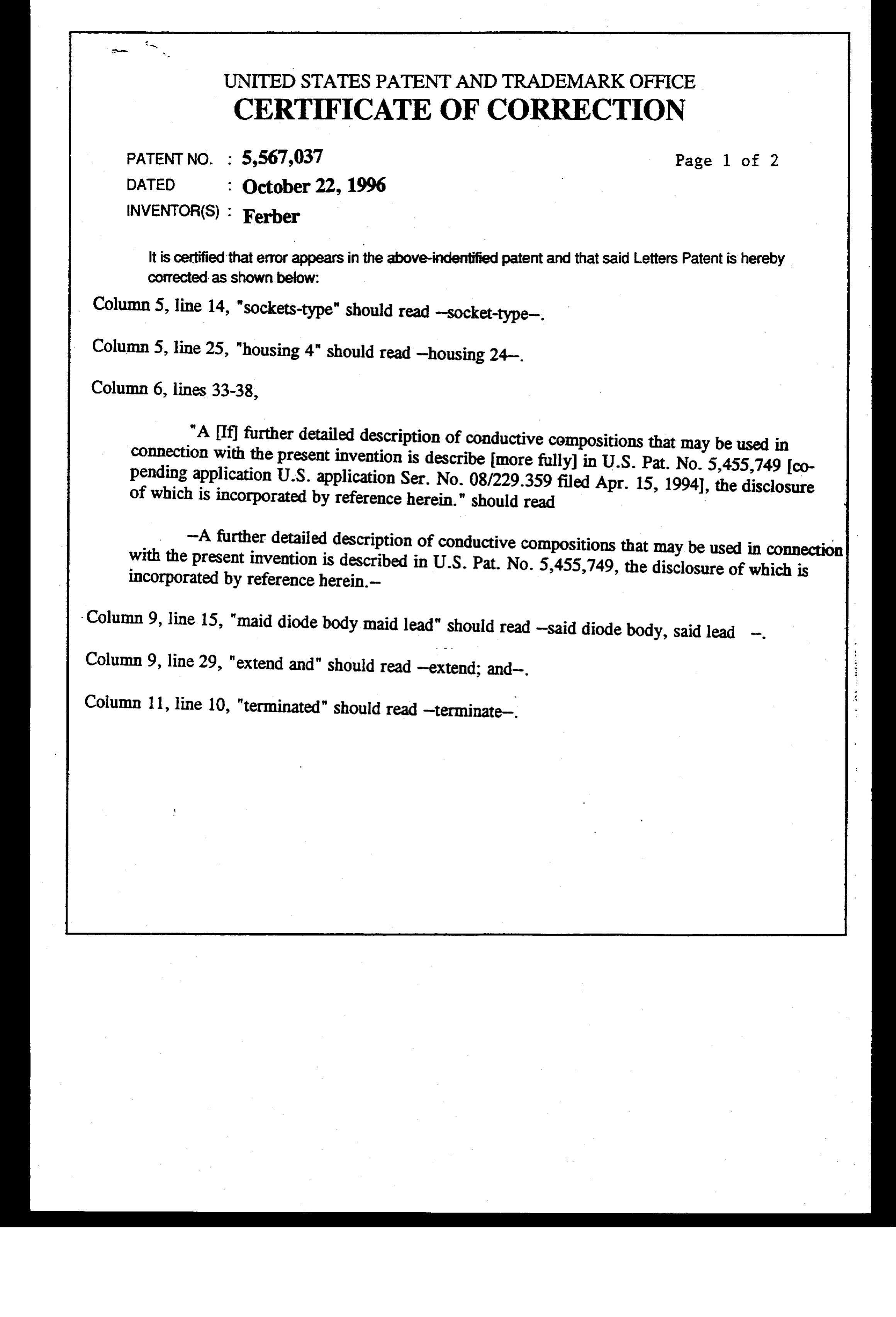
UNITED STATES PATENT ANDTRADEMARK OFFICE
CERT FICATE OF CORRECTION
PATENT NO. : 5,567,037 Page 1 of 2
INVENTOR(S) : Ferber
It is certified that error appears in the above-indentified patent and that said Letters Patent is hereby corrected as shown below:
Column 5, line 14, "sockets-type" should read -socket-type-.
Column 5, line 25, "housing 4" should read -housing 24-.
Column 6, lines 33-38,
"A Diffurther detailed description of conductive compositions that may be used in connection with the present invention is describe more fully in U.S. Pat. No. 5,455,749 co Pending application U.S. application Ser. No. 08/229.359 filed Apr. 15, 1994), the disclosure of which is incorporated by reference herein." should read
Column 9, line 15, "maid diode body maid lead" should read-said diode body, said lead -. Column 9, line 29, "extend and" should read-extend; and
Column 11, line 10, "terminated" should read-terminate
Page 14
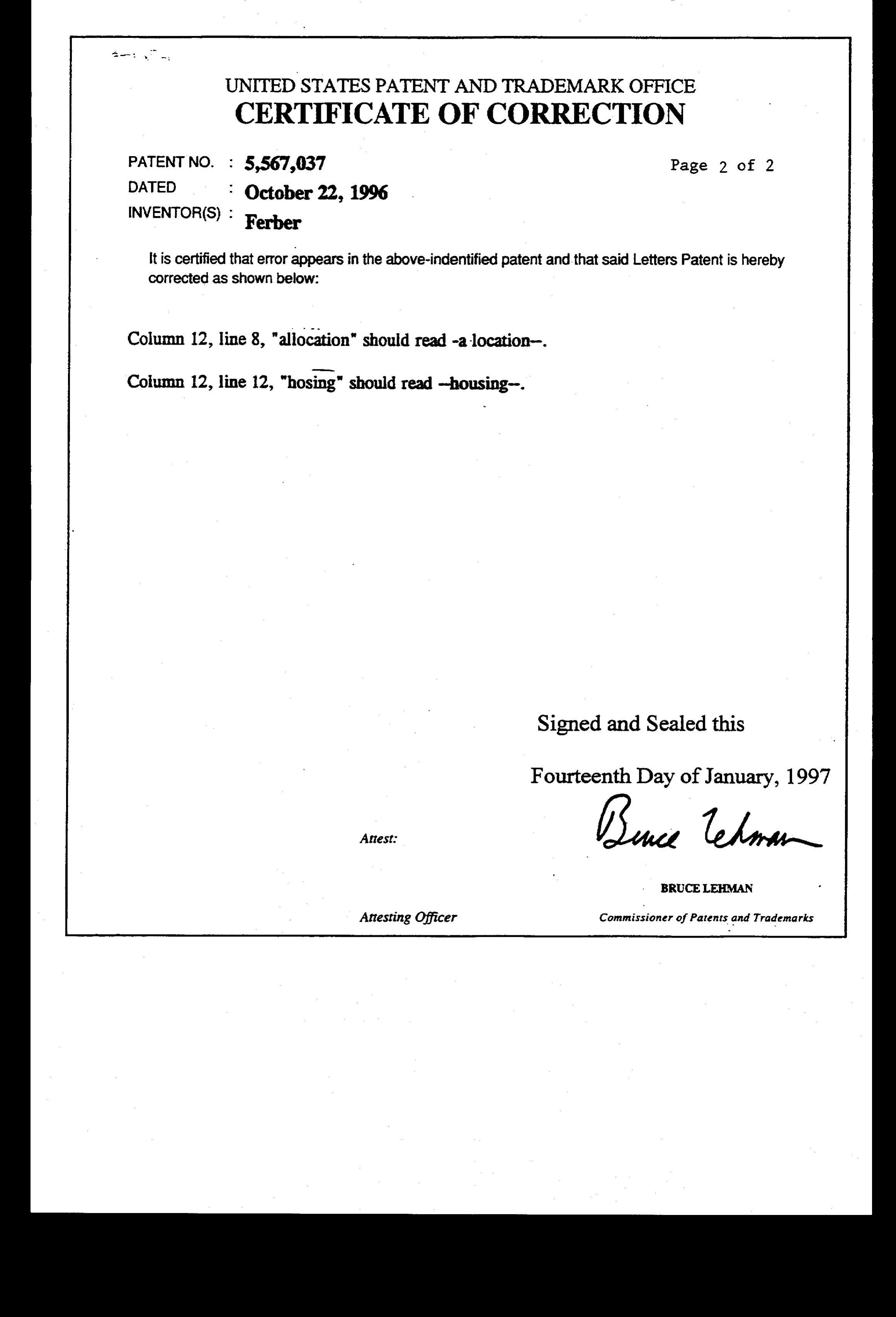
UNITED STATES PATENT ANDTRADEMARK OFFICE
CERTIFICATE OF CORRECTION
PATENT NO. : 5,567,037 Page 2 of 2
it is Certified that error appears in the above-indentified patent and that said Letters Patent is hereby Corrected as shown below:
Column 12, line 8, "allocation" should read-alocation
Column 12, line 12, "hosing" should read-housing
Signed and Sealed this
Fourteenth Day of January, 1997
(a tea
Attesting Officer Commissioner of Patents and Trademarks
Provenance
- Collection
- Cited prior art
- Original PDF
- patentimages.storage.googleapis.com →
- Filed
- 1995-05-03
- Pages
- 14
- Method
- pdftotext (the PDF's own text layer) + pdftoppm 300dpi page scans
- Source
- Google Patents bibliographic record
- Granted
- 1996-10-22
- Inventors
- Andrew R. Ferber; Ferber Tech LLC
- Transcribed from
- patentimages.storage.googleapis.com →