patent · US4124017A
Collimating solar radiation collector
7 November 1978
Page 1 — bibliographic record
35) a 96 a 2 3R
United States Patent (19) 11) 4,124,017 Paul 45 Nov. 7, 1978 (54) COLLIMATING SOLAR RADIATION lector which passively concentrates the rays of the sun. COLLECTOR The collector comprises a transparent cover which 75) Inventor: James B. Paul, Andover, Mass. collimates incident rays of light and directs such colli mated sunlight towards an absorbing target wherein the 73 Assignee: James B. Paul & Co., Inc., Boston, radiation's energy is received and utilized. The trans Mass.
parent collector cover consists of a lamination of trans (21) Appl. No.: 807,537 parent plastic or glass elements. Sunlight incident on the 22 Filed: Jun. 17, 1977 cover over a range of angles is reflected internally be tween the sides of the elements. These elements are so 51) Int. Cl.’................................................. F24J 3/02 shaped that internal reflections result in the sunlight 52 U.S. Cl. .................................... 126/270; 126/271; becoming collimated. Specifically, the elements are 350/96.12 curved so that the horizontal distance between the sides 58) Field of Search ................ 126/270, 271; 350/211, of adjacent elements remains constant whereas the 350/213,96 WG, 286 length of a normal between the sides increases along the (56) References Cited path of incident light. The effect of these apparently
reflection at a particular internal surface to occur at a 3,970,070 7/1976 Meyer et al.......................... 126/271 successively lower angle of incidence, thus tending to 3,985,116 10/1976 Kapany ................................ 126/271 collimate the light's rays. The resulting collimated rays Primary Examiner-Kenneth W. Sprague are then reflected upon leaving the bottom of the col Attorney, Agent, or Firm-Cooper, Dunham, Clark, lector cover in such a way that they are directed Griffin & Moran towards the absorbing target.
This invention describes an improved solar energy col 15 Claims, 3 Drawing Figures
Page 2
Drawing sheet — no readable text.
Page 3
indirect sunlight and for concentrating solar energey in
COLLMIATING SOLAR RADATION amounts sufficient for heating and/or cooling buildings. COLLECTOR It is another object of the invention to provide an BACKGROUND OF THE INVENTION improved solar energy collector having a new and use 5 ful system of curved, laminated transparent elements for
Solar radiation has long been recognized as an energy collimating solar radiation and concentrating solar en source with many potential applications. However, ergy by directing collimated radiation upon an absorb until recently the ease of recovery and relatively low ing target.
cost of fossil fuels have resulted in the postponement of It is a further object of the invention to provide an efforts to utilize this virtually limitless and non-pollut 10 improved device for concentrating solar energy which ing energy source. Present concern over the depletion does not require an expensive and complicated tracking of fossil fuels has now brought about renewed interest in mechanism.
tapping the energy inherent in the sun's radiation. SUMMARY OF THE INVENTION Flat-plate solar collectors are commonly used for hot water and space heating. However, flat-plate collectors 15 The invention, accordingly, comprises one or more possess certain inherent disadvantages which deter transparent collecting covers, each formed from thin wider application. Specifically, flat-plate collectors lose strips of a transparent material, such as acrylic or glass. efficiency as the collector temperature increases over These strips of transparent material, hereinafter called the temperature of the ambient atmosphere. Since the 20 elements, are laminated together. In section, the long entire upper surface area of the collector is available for edges of the elements, curved in the form of a parabloid, transferring heat to the outside, heat loss increases as are contiguous. Their length coincides with the thick the temperature of the collector rises. Not only does ness of the cover. The short edge of the element, again this heat loss problem reduce the collector's efficiency, in section, is flat on its upper surface and coincides with it also imposes a practical limit on the temperature to 25 the upper surface of the collecting cover. The bottom which a fluid interfacing the collector can be raised. edge of the element is sharply angled in order to refract Hence, flat-plate collectors have only been used for collimated light in the direction of an absorbing target. relatively low temperature heat applications, such as receive the below
Positioned the collecting cover in a position to concentrated solar radiation is it is refracted space heating, and have not been suitable for higher from temperature fluid applications, such as absorption cool 30 targetthecapablelower angled edge of the cover is an absorbing of transforming the radiation into ther ing and other thermodynamic cycles. An additional mal or some other form of energy. disadvantage associated with flat-plate collectors is the cost of the relatively large surface area of materials collecting cover at an angleupon
Solar radiation incident less the upper edge of the than the critical angle required to absorb incident light. for the material of which the cover is composed enters In order to attain higher temperatures than possible 35 the elements. It is reflected downward with flat-plate collectors, concentrating collectors have surface by the edges of the elements from and the upper collimated been developed. Such devices concentrate incident because of the shape of the elements. The resulting solar radiation upon a relatively small absorption area, collimated solar radiation is refracted upon leaving the typically by some type of imaging process. Although angled higher temperatures have been obtained with such con towards bottom edge of the element and directed the absorbing target.
centrating collectors, they too have certain deficiencies.
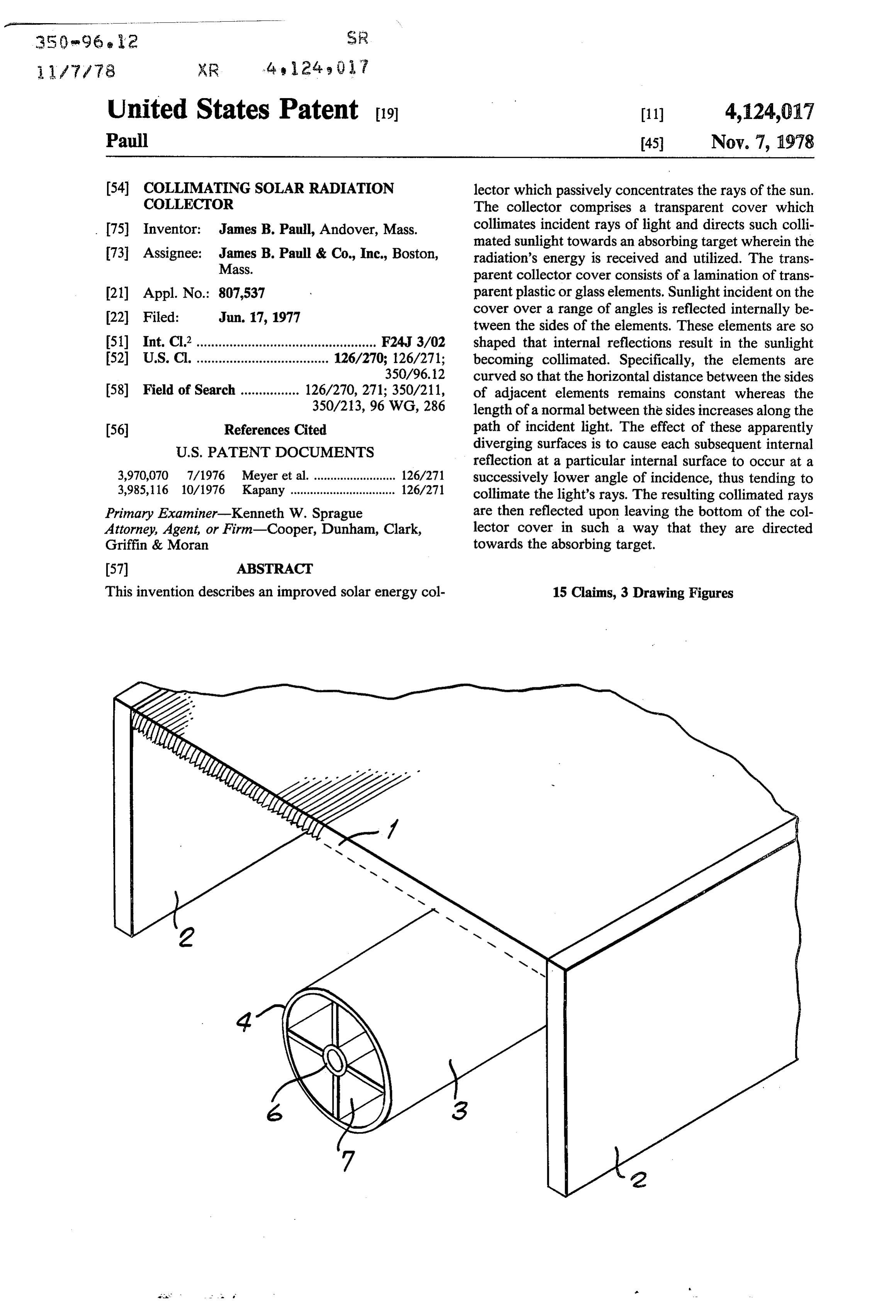
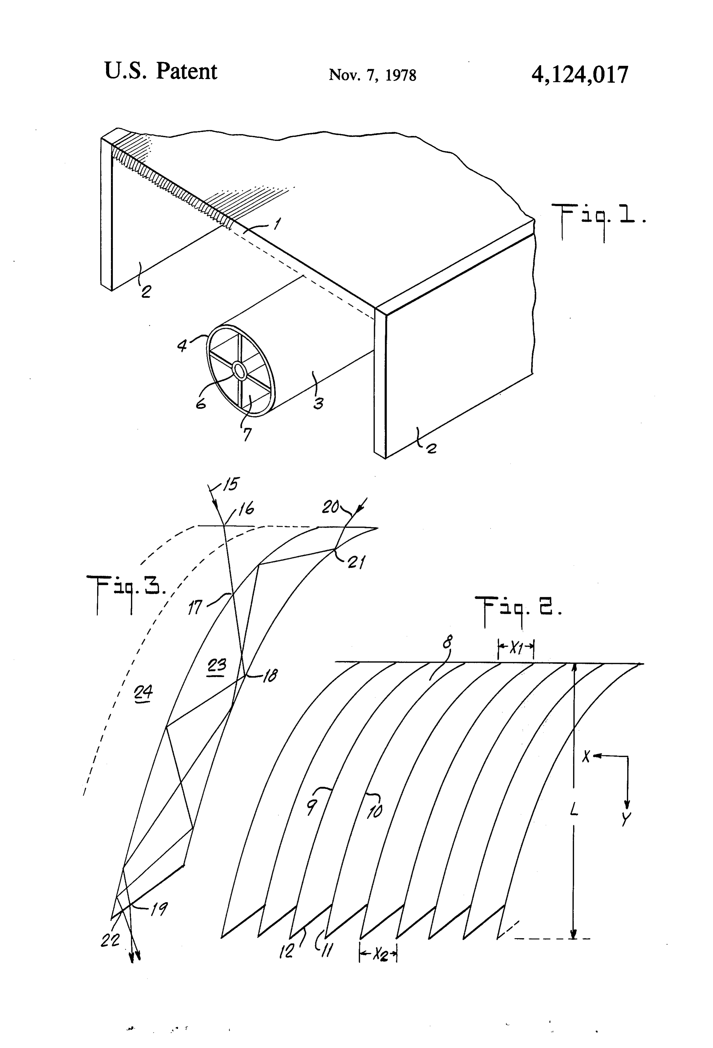
In particular, in order to capture solar radiation they BRIEF DESCRIPTION OF THE DRAWINGS must at least roughly track the path of the sun. This FIG. 1 is an isometric view of a representative solar requires a complicated mechanism for moving the con energy collector assembly, including transparent col centrating collector which adds a substantial expense to 45 lecting cover, supports, and absorbing device. the overall device and involves regular maintenance FIG. 2 is a section through the collecting cover, and the possibility of mechanical failure. Furthermore, showing the general arrangement of the contiguous because these concentrating collectors are designed for elements.
capturing direct sunlight, much of the diffuse sunlight FIG. 3 is an expanded view, in section, of one element goes uncollected. As a result, on overcast days, and in 50 showing several possible paths of light. northern latitudes where a large percentage of incident sunlight is diffuse, such collectors are not optimally SPECIFIC DESCRIPTION OF THE INVENTION functional. Referring to the several drawings in detail, FIG. 1 One solution to the problems inherent with both flat shows a representative solar energy collector assembly plate and concentrating collectors is to passively con 55 comprising a transparent collecting cover 1, base sup centrate incident sunlight, both direct and diffuse, with ports 2 upon which said cover is mounted, and a solar out the aid of a tracking mechanism. Several of these absorbing device 3 such as exists in the art. It is possible non-tracking solar concentrating collectors exist in the to utilize a wide range of absorber designs. This particu prior art, such as those of U.S. Pat. Nos. 3,915,148; lar design is merely set forth by way of example. In the 3,923,381; 3,964,464 and 3,780,722. However, unlike the 60 design shown, absorber 3 consists of a cylindrical glass invention disclosed herein, none of these devices colli outer surface 4 which admits the collimated solar radia mate the sun's rays which they collect. Such collimation tion directed upon the absorber from the lower surface permits improved concentration upon an absorbing of the cover and prevents heat loss from the collector, target by a simple and relatively inexpensive collector metal surfaces 7 which absorb the solar radiation and possessing a number of novel and advantageous features 65 convert it to thermal energy, and metal conduit 6 to as revealed in the following disclosure. which said metal surfaces are attached. Conduit 6 func The principal object of this invention is to provide a tions to carry a fluid which receives and transports the new and useful device for collecting both direct and collected thermal energy.
Page 4
Cover 1 and absorber 3 function optimally when approximate the range of angles of the light being re aligned along a North-South axis. Solar radiation inci flected from surface 10 at about the bottom of element dent upon the cover is collimated and refracted upon 8. Without providing this geometry, collimated light is leaving the bottom surface of the cover in such a way generally reflected in two directions: from surface 9 and that the collimated sunlight is directed upon absorber 3. from surface 10. With this geometry a very high per It is known that light incident upon one of two con centage of the total light is ultimately reflected from verging reflective surfaces reflects between the surfaces surface 9.
such that the angle of incidence increases for each sub The second function of angled edge 12 is to refract sequent reflection. Conversely, the angle of incidence the light emanating from the bottom of element 8 so that of light reflecting between two diverging surfaces pro O there is little interference with the lower edge of adjoin gressively decreases, such reflected light tending to ing element 11.
approach the angle of a line equidistant from the two The third function of angled bottom edge 2 is to surfaces. The number of reflections between surfaces refract the collimated light towards an absorbing target. can be increased if the diverging surfaces are curved, The angle of edge 12 can be increased to varying angles since light travels in a straight path. As a result, the light 15 above that necessary to eliminate interference and to is collimated between the diverging surfaces. direct the collimated light from the element toward the In the presently preferred embodiment of this inven target.
tion, the curved diverging surfaces used to collimate the Light incident at an angle on the surface of cover 1 light are the sides of a solid transparent element com will be refracted to a steeper angle as it passes into a posed of a material such as acrylic or glass. The collima 20 more dense medium. For purposes of illustrating, con tion is effected by internal reflections of light from the sider sunlight incident over a range of 90 degrees, corre sides of the element. sponding to the range of the apparent motion of the sun To better understand this phenomenon reference is over a period of approximately (6) hours. Assuming the made to FIG. 2, a sectional view through the collecting material of the cover is acrylic with a refractive index of cover, which depicts a plurality of contiguous elements 25 1.49, the total range of angular incidence is reduced to 8. Elements 8 are curved and of constant thickness, i.e. a total of 54 upon entering the cover. the distance between the surfaces 9 and 10 of element 8 FIG.3 depicts two of the many possible paths of light is constant (X =X2). Because of the curved shape, through the elements of collecting cover i. In one ex however, a normal from a point on the surface of one ample, a path of light 15 enters cover 1 at 16 and is side of the element to the other side of the same element 30 refracted to a steeper angle. At 17, the light reaches the increases as said point on the surface becomes more side of particular element 24. As the angle of incidence distant from the upper surface of the element along the with the side is greater than the critical angle of the Y-axis. Thus, light entering a particular element 8 will material for internal reflection, the light passes through be reflected internally within the element by sides 9 and the interface between the elements into adjoining reflec 10. Each subsequent reflection from a side will occur at 35 tive element 23. At the opposite edge of element 23, the a lower angle of incidence, thereby collimating the angle of incidence at 18 is less than the critical angle, light. and the light is reflected internally. The light continues There are several general considerations regarding to be reflected internally between the sides of element the shape and dimensions of the elements. As mentioned 23, until it exits the element and is refracted at 19. above, the elements should be of constant width As a second example, light path 20 enters cover 1 and (X=X2) along the X-axis. The greater the variation is refracted. Upon reaching the side of particular ele from constant width the greater the curvature in the ment 23 at 21, the angle of incidence is less than the cover and the poorer the performance of the collector. critical angle, and the light is reflected internally. As in The shape of sides 9 and 10 of the elements are of the the previous example, the light continues to be reflected general form Y = X, X 2 0. Practical limitations sug 45 internally until it exits element 23 and is refracted at 22. gest an in 2 1.7, with the best performance in the range Other configurations of the device of this invention 2 is n is 3.5. Practical considerations also suggest that are possible. More than one collecting cover may be the initial X be chosen for the curve such that 0 is used to increase efficiency. Light collimated in an upper dy/dx is 1.3. collecting cover then enters a second collecting cover The maximum slope, s, of the curve of the long edge 50 below, where further collimation is achieved. The should be such that s > 8. Such a steep slope is neces lower edges of the last of a series of collecting covers sary to insure that light incident on the sides of the are angled to refract the light to the target. elements at high incident angles reaches a point where In another embodiment of the invention, light is not the incident angle is less than the critical angle of the refracted to the absorbing target by the lower edges of material, at which point the light is reflected internally. 55 the collecting cover. Instead, the collimated light is Another important consideration in the design of the reflected to the target by a reflecting surface below the shape of the elements is the ratio of length L to width collector.
X1. This ratio is important for two reasons. First, L/X1 In a further embodiment of the invention, the surface must be large enough to cause a number of reflections of the collector cover is angled such that the side edges sufficient to achieve a satisfactory degree of light colli 60 of the elements can be described by the curves Y=X mation. Secondly, L/X1 must be large enough so that and (y-r)=X", where r is the vertical rise of the sur incident light cannot pass through the element without face of the collector with respect to the width of an being reflected at least once by the sides of the element. element X1.
The sharp angle of bottom edge 12 of the elements 8 In still another embodiment of the invention a reflec serves three functions. In element 8, for example, the 65 tive material is placed at the interface of the elements. angle of edge 12 ensures that light or solar energy is Collimation then no longer depends on internal reflec ultimately reflected from surface 9 before leaving ele tions within the elements but results from simple reflec ment 8. For this to occur, the angle of edge 12 should tions from adjacent reflective surfaces.
Page 5
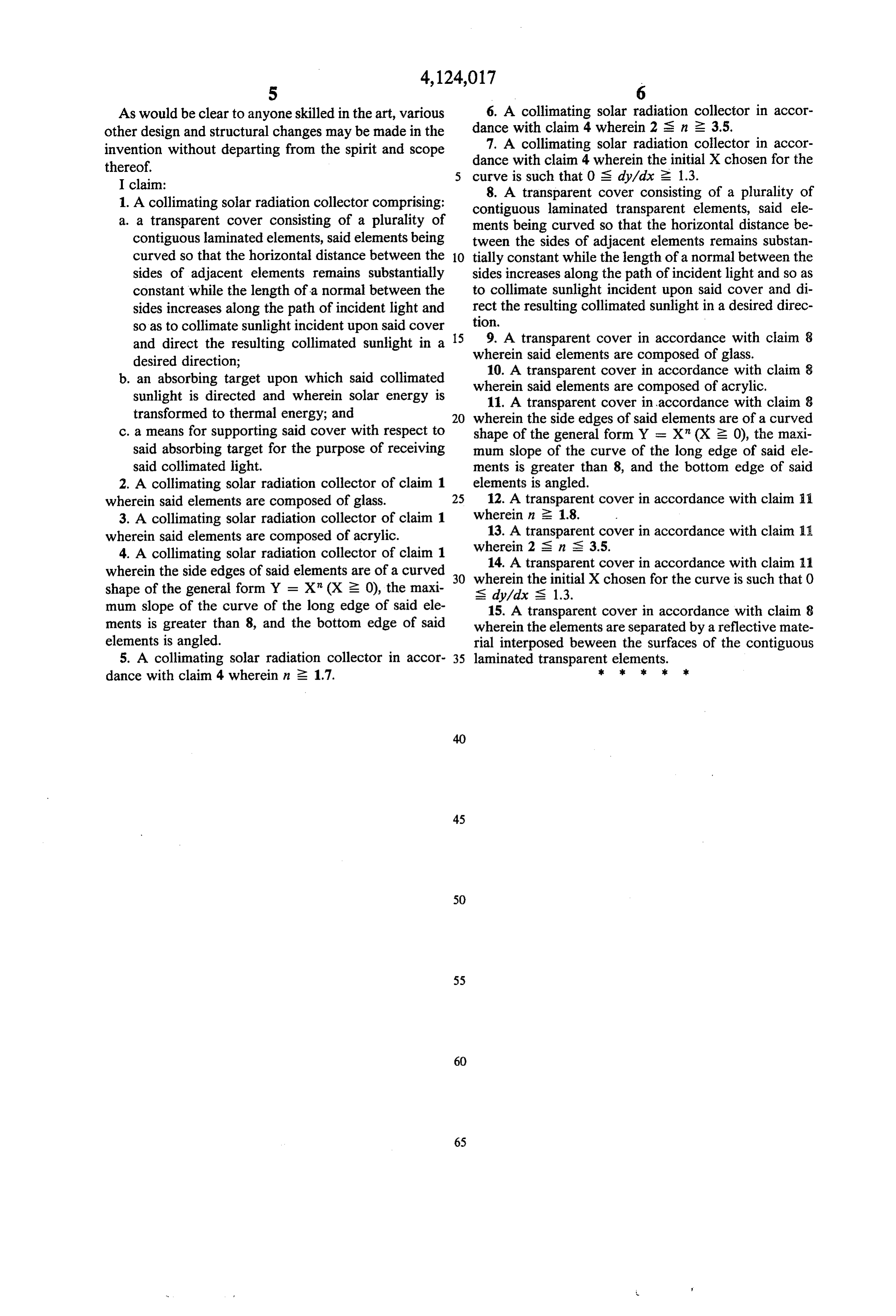
As would be clear to anyone skilled in the art, various 6. A collimating solar radiation collector in accor other design and structural changes may be made in the dance with claim 4 wherein 2 S. n 2 3.5. invention without departing from the spirit and scope dance 7. A collimating solar radiation collector in accor thereof. with claim 4 wherein the initial X chosen for the I claim: curve is such that 0 is dy/dx 2 1.3. 1. A collimating solar radiation collector comprising: contiguous laminatedcover 8. A transparent consisting of a plurality of transparent elements, said ele a. a transparent cover consisting of a plurality of ments being curved so that the horizontal distance be contiguous laminated elements, said elements being tween the sides of adjacent elements remains substan curved so that the horizontal distance between the 10 tially constant while the length of a normal between the sides of adjacent elements remains substantially sides increases along the path of incident light and so as constant while the length of a normal between the to collimate sunlight incident upon said cover and di sides increases along the path of incident light and rect the resulting collimated sunlight in a desired direc so as to collimate sunlight incident upon said cover tion.
and direct the resulting collimated sunlight in a 15 9. A transparent cover in accordance with claim 8 wherein said elements are composed of glass.
desired direction; 10. A transparent cover in accordance with claim 8 b. an absorbing target upon which said collimated wherein said elements are composed of acrylic, sunlight is directed and wherein solar energy is 11. A transparent cover in accordance with claim 8 transformed to thermal energy; and wherein the side edges of said elements are of a curved c. a means for supporting said cover with respect to shape of the general form Y = X" (X 2 0), the maxi said absorbing target for the purpose of receiving mum slope of the curve of the long edge of said ele said collimated light. ments is greater than 8, and the bottom edge of said 2. A collimating solar radiation collector of claim 1 elements is angled.
wherein said elements are composed of glass. 25 12. A transparent cover in accordance with claim a 3. A collimating solar radiation collector of claim 1 wherein in 2 1.8.
wherein said elements are composed of acrylic. 13. A transparent cover in accordance with claim 1 wherein 2 S in S 3.5.
4. A collimating solar radiation collector of claim 1 14. A transparent cover in accordance with claim 11 wherein the side edges of said elements are of a curved 30 wherein the initial X chosen for the curve is such that 0 shape of the general form Y = X" (X 2 0), the maxi S dy/dx is 1.3.
mum slope of the curve of the long edge of said ele 15. A transparent cover in accordance with claim 8 ments is greater than 8, and the bottom edge of said wherein the elements are separated by a reflective mate elements is angled. rial interposed beween the surfaces of the contiguous 5. A collimating solar radiation collector in accor 35 laminated transparent elements.
dance with claim 4 wherein in 2 1.7.
Page 6
UNITED STATES PATENT AND TRADEMARK OFFICE
CERTIFICATE OF CORRECTION
INVENTOR(S) : James B. Paull
It is certified that error appears in the above-identified patent and that said Letters Patent are hereby Corrected as shown below:
Column 2, line 20, the word "reflected" should read -- refracted-- ;
Column 2 line 28, the word "is" should read
Claim 6, Column 6, line 2, before 3.5, the symbol
Claim 7, Column 6 line 5, before 1.3, the symbol
eigned and Sealed this
Twentieth D ay of February 1979
SEAL
Attest:
DONALD W. BANNER
RUTH C. MASON
Attesting Officer Commissioner of Patents and Trademarks

Provenance
- Collection
- Patents citing this work
- Original assignee
- JAMES B PAULL AND CO Inc
- Pages
- 6
- Method
- pdftotext (the PDF's own text layer) + pdftoppm 300dpi page scans
- Patent office record
- patents.google.com →
- Source
- Google Patents citing-documents table
- Inventors
- James B. Paull; JAMES B PAULL AND CO Inc
- Published
- 1978-11-07
- Transcribed from
- patentimages.storage.googleapis.com →