patent · US5001609
Nonimaging light source
19 March 1991
Page 1 — bibliographic record
United States Patent (19) 11 Patent Number: 5,001,609 Gardner et al. 45 Date of Patent: Mar. 19, 1991 (54) NONIMAGING LIGHT SOURCE 4,651,261 3/1987 Szekacs ........................... 362/.336 X 4,684,919 8/1987 Hihi.............. ... 362/307 X 75 Inventors: Robert C. Gardner; David E. 4,698,730 10/1987 Sakai et al. ... 362/800X Silverglate; Greg P. Smestad; George 4,742,432 5/1988 Thillays .......................... 362/800X E. Smith, all of San Jose; John F. FOREIGN PATENT DOCUMENTS
Snyder, Sunnyvale, all of Calif.
73 Assignee: Hewlett-Packard Company, Palo 6045452 9/1983 Japan.
Alto, Calif.
OTHER PUBLICATIONS
(22) Filed: Oct. 5, 1988 Von M. Ploke, Carl Zeiss; "Lichtfuhrungseinrichtun gen mit starker Konzeutrationswirkung", 10/1967.
51 int. Cli................................................ F2V 7/09 X. Ning, R. Winston, J. O'Gallagher; "Dielectic totally 52 U.S. C. ...................................... 362/32; 362/297; internally reflecting concentractors", Applied Optics, 362/346; 362/347; 362/800; 357/17; 357/70 15 Jan. 1987, p. 300-305.
58) Field of Search ............... 357/17, 69, 70; 362/32, "Aperture without Restricting Angular Acceptance', 362/297, 298,302, 346, 347, 800, 336,337,338, The Enrico Fermi Institute, Apr. 8, 1968. 339 H. Hinterberger and R. Winston, "Efficient Light Cou (56) References Cited pler for Threshold Cerenkov Counters,', Enrico Fermi
Primary Examiner-Stephen F. Husar 3,609,475 9/1971 Kaposhilin ...................... 313/108 D Assistant Examiner-Peggy A. Neils 3,780,357 12/1973 Haitz ............ ... 33/108 D 3,821,775 6/1974 Biard ..................................... 357/17 57 ABSTRACT 3,875,456 4/1975 Kano et al... . 357/17 X The principles of non-imaging optics, rather than imag 3,923,381 12/1975 Winston .............................. 350/293 3,957,031 5/1976 Winston ... ... 350/293 ing optics, are used to provide a high power LED illum 4,002,499 1/1977 Winston ... ... 250/228 ination lamp that has a specified limited viewing angle. 4,003,638 1/1977 Winston ... ... 350/293 A compound parabolic flux extractor extracts and con 4,045,246 8/1977 Miavsky ... ... 126/270 centrates light emitted by an LED chip and a light pipe 4,114,592 9/1978 Winston ....... ... 350/293 continues the concentration into the specified viewing 4,130,10712/1978 Rablet al. ... 350/293 angle. A lens or a diffusant may be used to modify the 4,230,095 10/1980 Winston ... 350/293 light output of the lamp. A light constructed as an array 4,237,332 12/1980 Winston ... ... 136/259 of the lamps is suitable for use as an automobile external 4,240,692 12/1980 Winston ... ... 126/438 4,359,265 11/1982 Winston ... ... 350/246 light such as a center high mounted stop light. 4,387,961 6/1983 Winston ... ... 350/296 4,483,007 ll/1984 Winston ................................ 372/72 21 Claims, 9 Drawing Sheets
Page 2
Drawing sheet — no readable text.
Page 3
Drawing sheet — no readable text.
Page 4
Drawing sheet — no readable text.
Page 5
Drawing sheet — no readable text.
Page 6
Drawing sheet — no readable text.
Page 7
Drawing sheet — no readable text.
Page 8
Drawing sheet — no readable text.
Page 9
Drawing sheet — no readable text.
Page 10
Drawing sheet — no readable text.
Page 11
light. A bulk diffusant may be located within the struc
NON MAGNG LIGHT SOURCE ture of the lamp itself or a diffusing layer may be posi tioned over the lamp. The diffusant operates to increase
BACKGROUND AND SUMMARY OF THE the apparent size of the illuminated area, to decrease the INVENTION 5 brightness of the lamp and to increase the flux diver Light emitting diodes (LEDs) are becoming increas gence the to an approximately Lambertian distribution at diffusant surface.
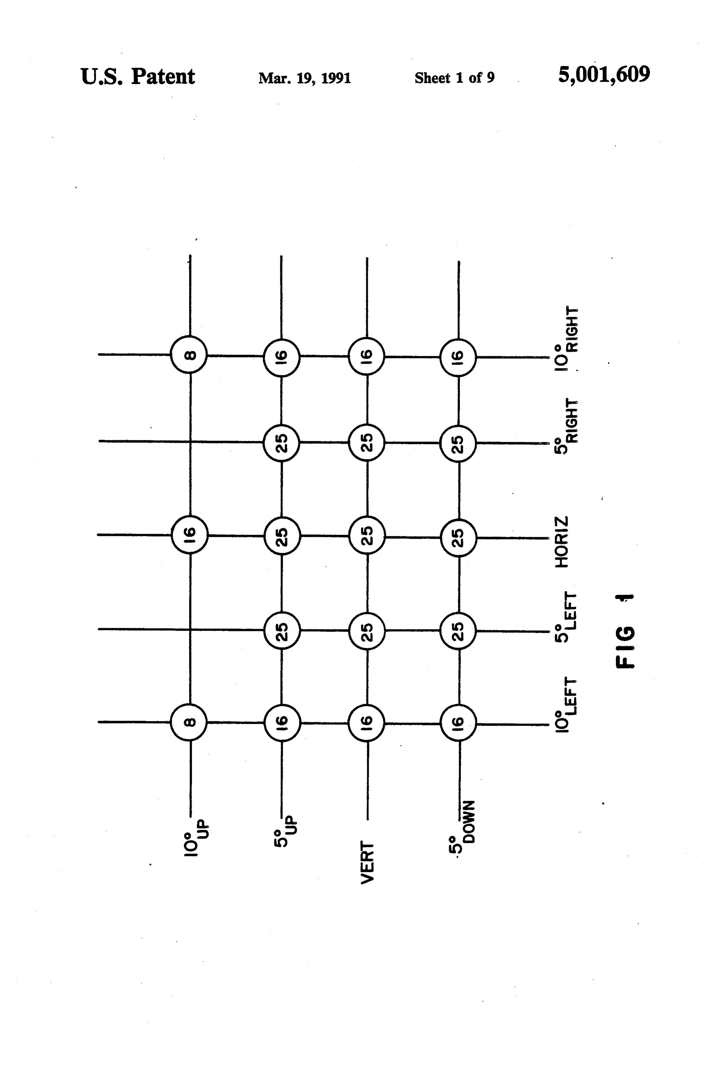
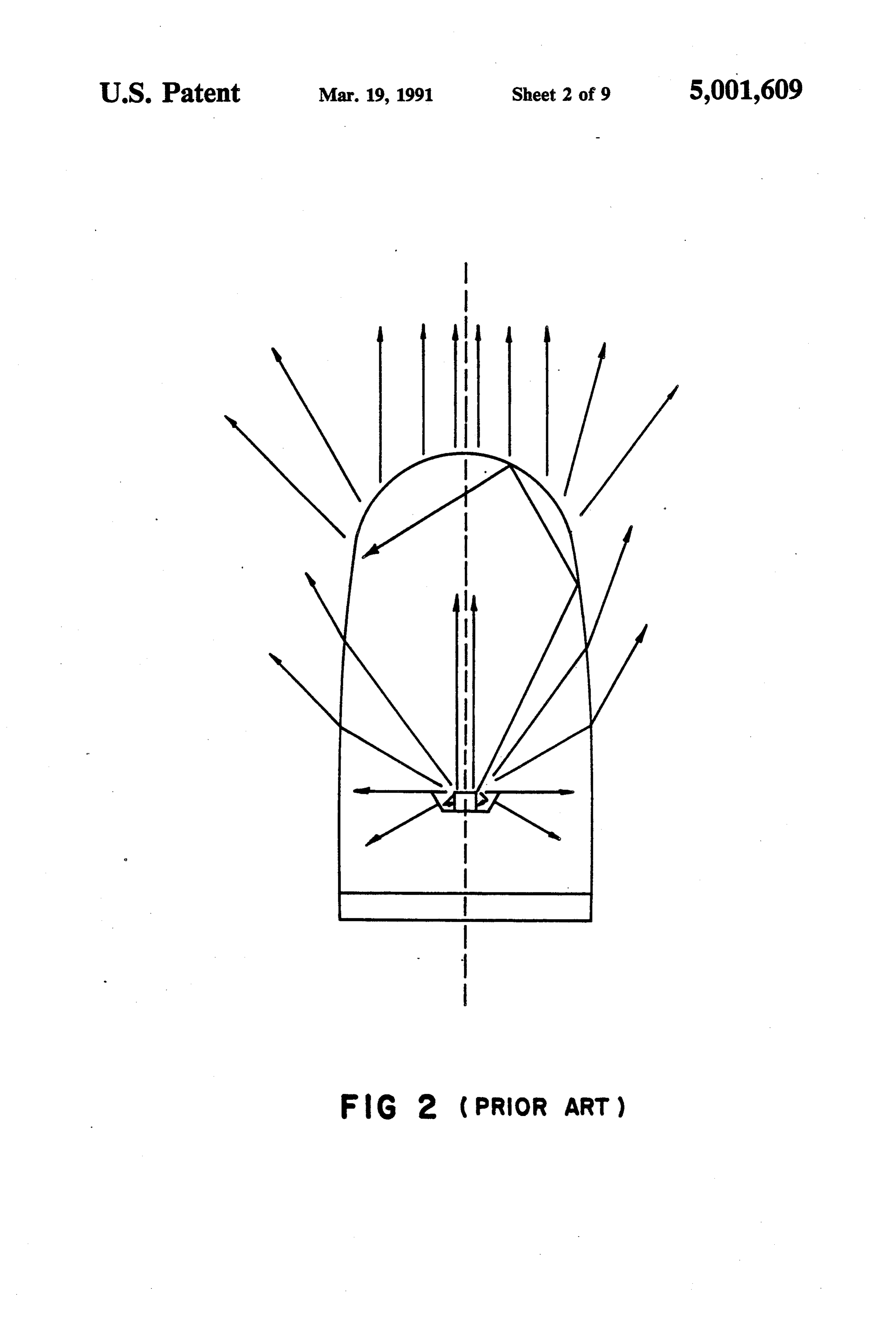
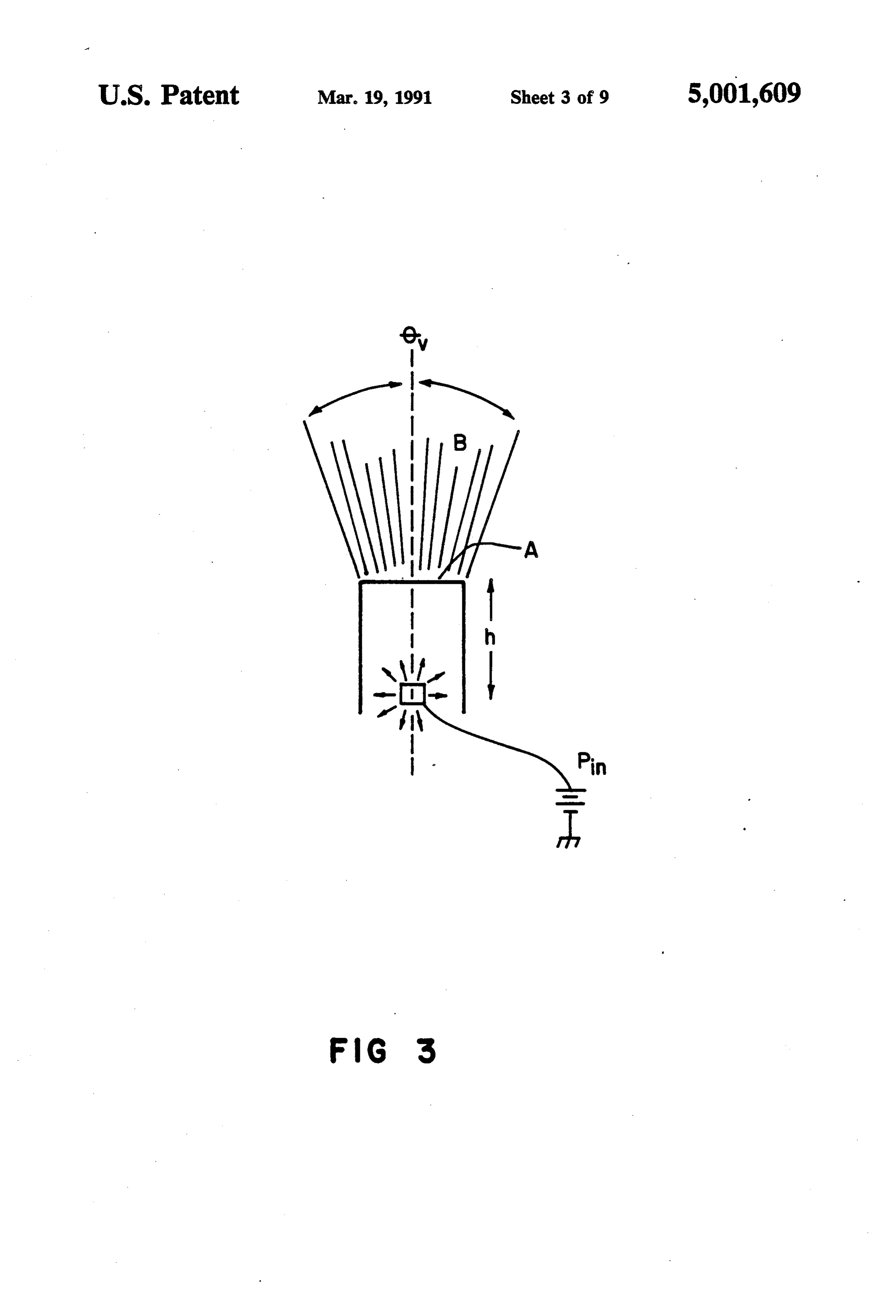
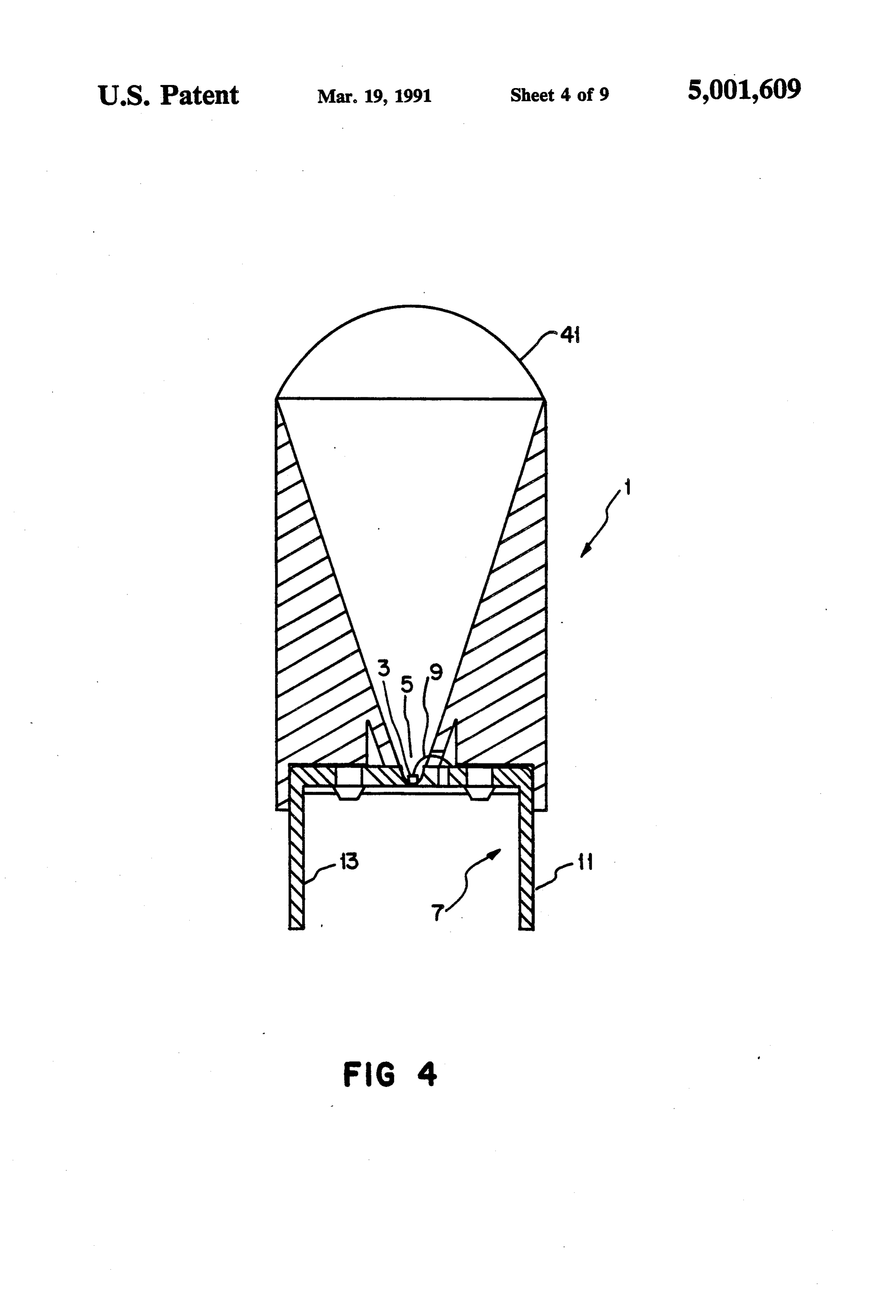
ingly widely used in automobile design because of their longer lives and lower cost compared to the incandes BRIEF DESCRIPTION OF THE DRAWINGS cent bulbs they replace. Present day automotive design 10 ers are specifying LEDs not only for indicator lamps FIG. 1 shows the U.S. federal specification for the and alphanumeric digits but also for high power illumi brightness of an LED automobile center high mounted nation lamps such as center high mounted stop lights. stop light as a function of viewing angle. LED stop lights require very high brightness, but often FIG. 2 shows a prior art LED lamp designed accord only over a very limited viewing angle. FIG. 1 shows ing to the principles of imaging optics the current U.S. federal standard for LED center high FIG. 3 shows various design parameters that are mounted stop light brightness in candela as a function of important to the design of an LED illumination lamp. viewing angle. FIG. 4 shows an LED illumination lamp that is con In order to be cost competitive with incandescent structed in accordance with a preferred embodiment of bulbs, an LED stop light must contain only a minimum 20 the present invention.
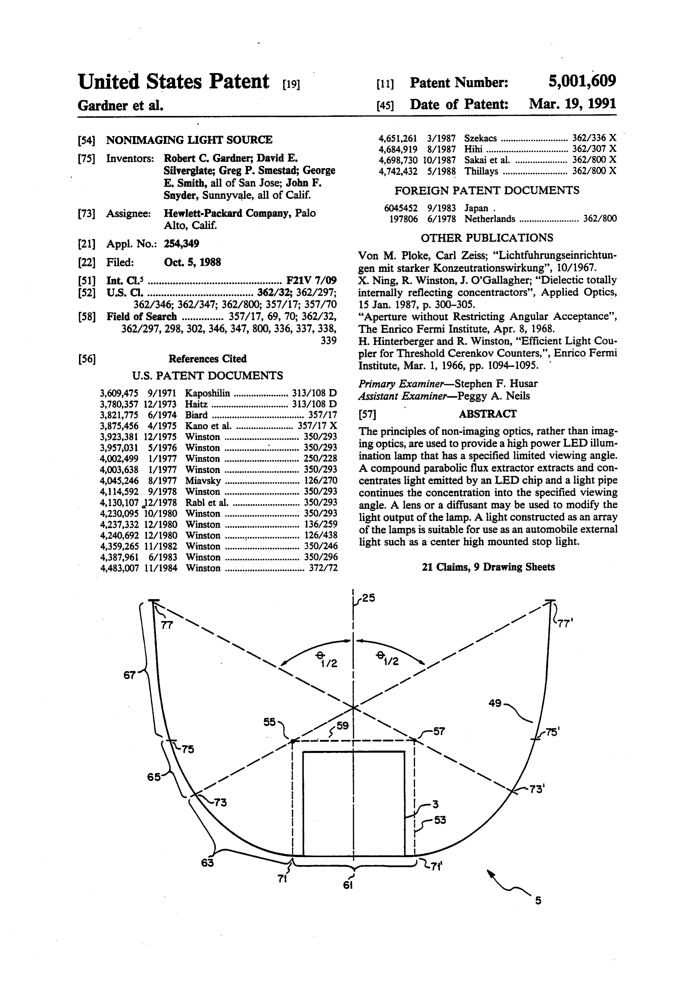
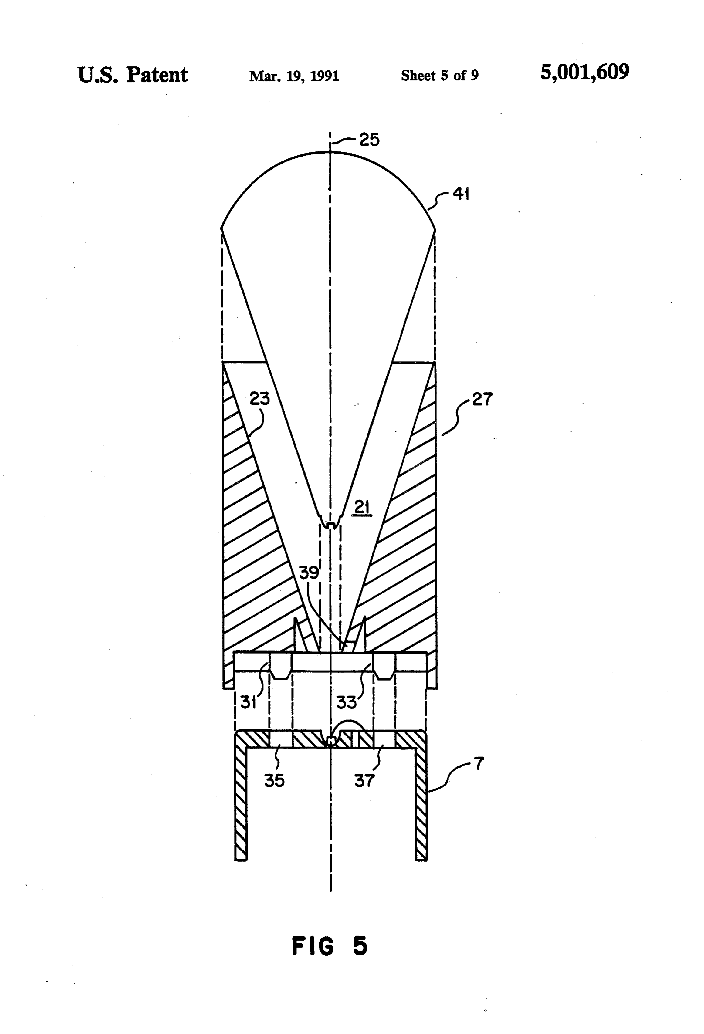
number of individual LED lamps. The number of indi FIG. 5 is an exploded view of the LED illumination vidual lamps can only be minimized if each lamp ex lamp shown in FIG. 4.
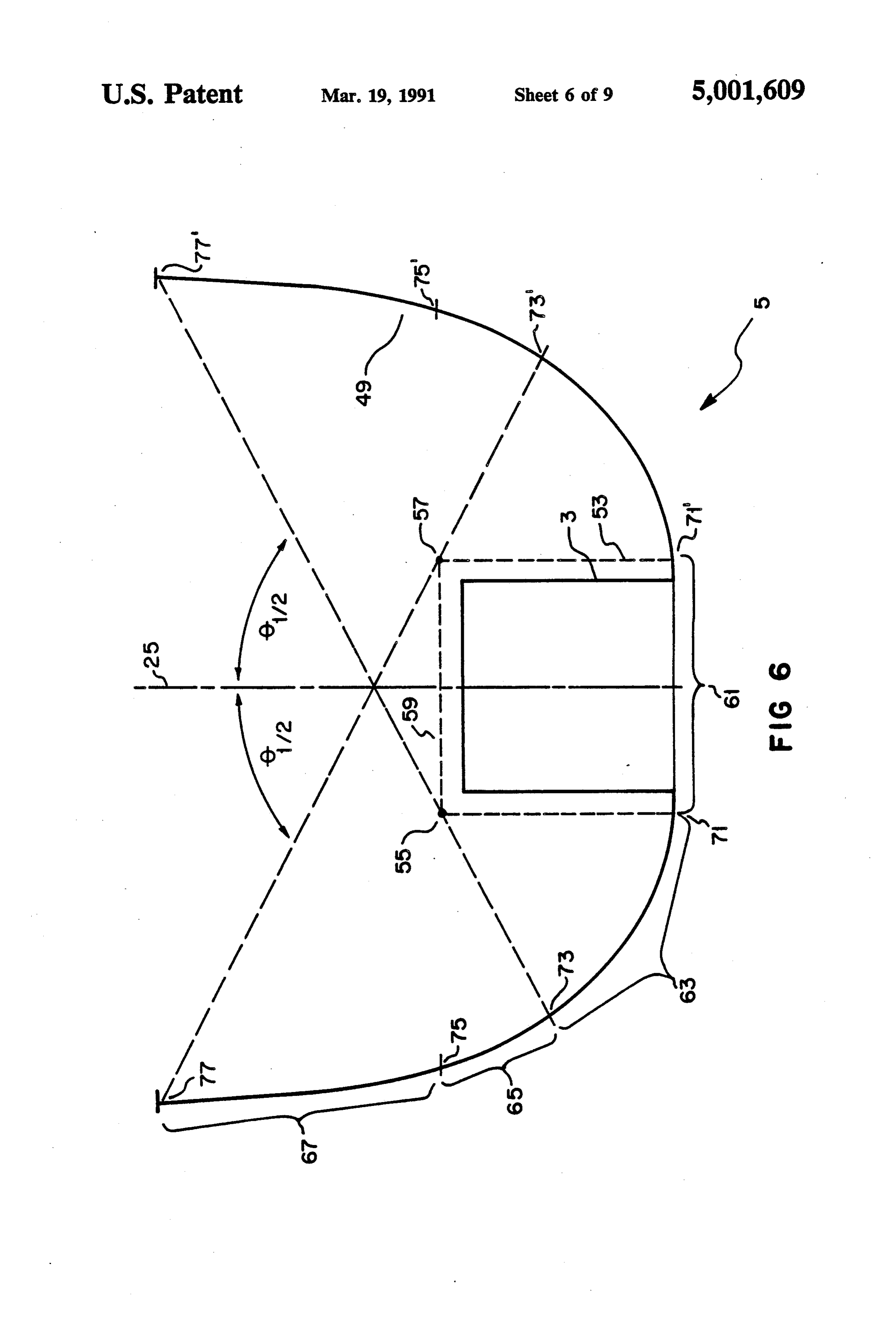
tracts substantially all of the light flux from the LED FIG. 6 is a detail view of the flux extractor shown in chip and concentrates the light within the useful view FIG. 4.
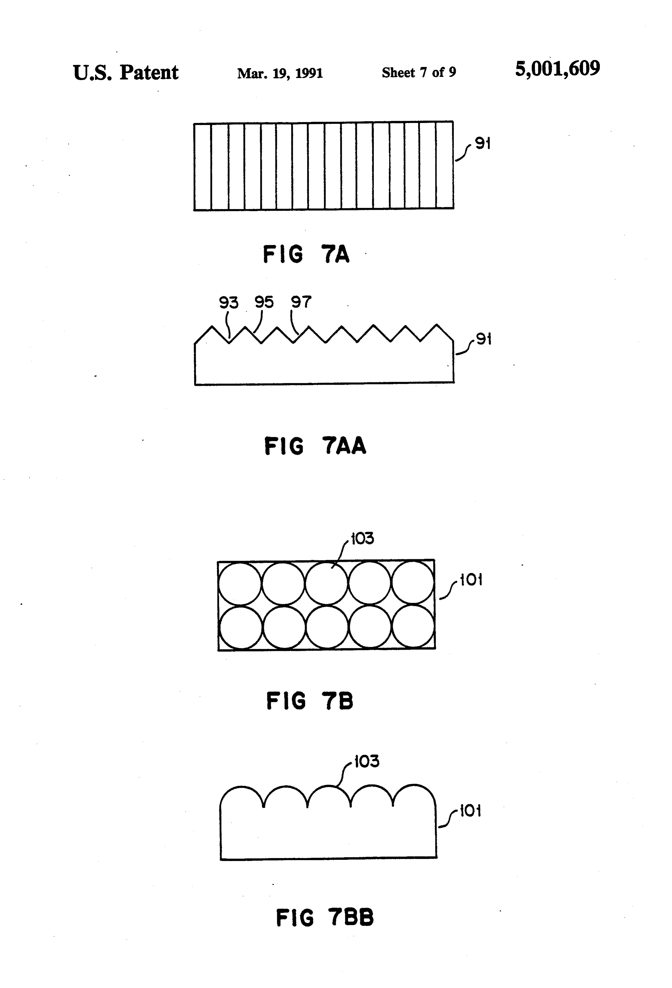
ing angle. Light flux outside of the viewing angle is FIGS. 7A-B show a number of lenses that may be wasted and might have been available to increase 25 used in the lamp shown in FIG. 4.
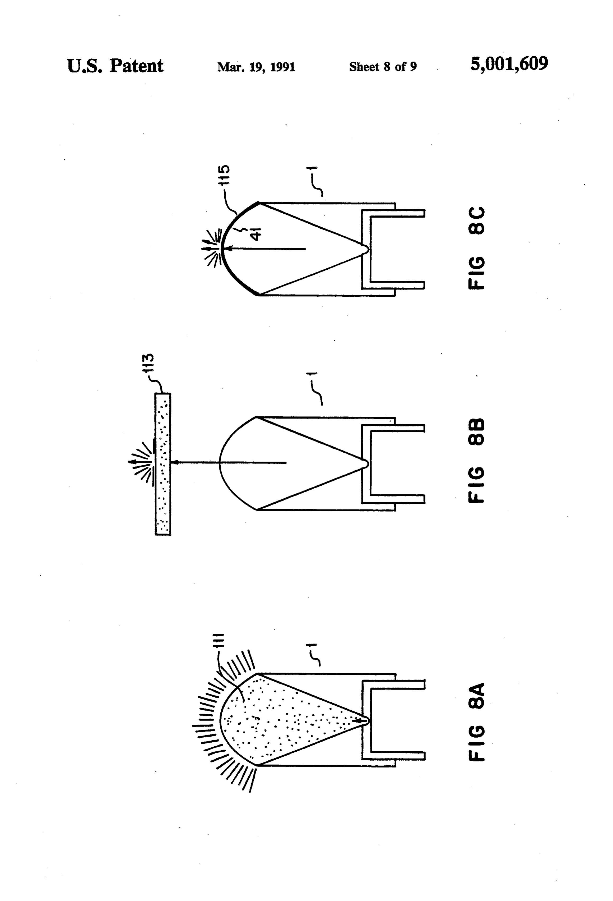
brightness within the viewing angle. Commercially FIGS. 8A-C show the use of diffusant with the lamp available indicator lamps, which are designed according shown in FIG, 4.
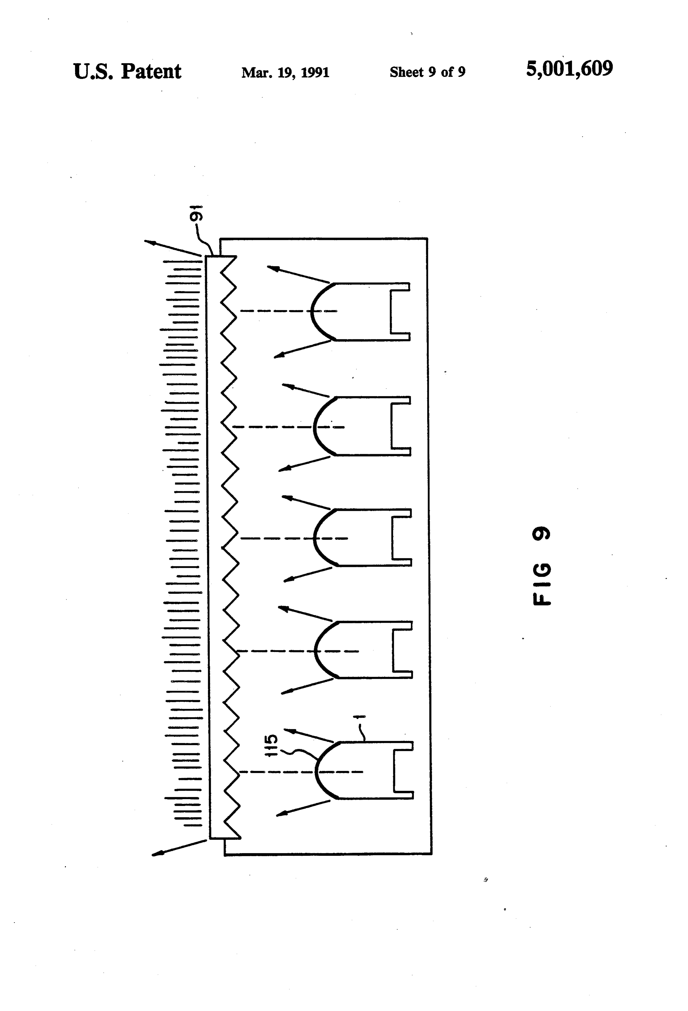
to the principles of imaging optics and standard manu FIG. 9 shows a center high mounted stop light con facturing techniques, fail to concentrate sufficient light structed as an array of the lamps shown in FIG. 4. flux within the narrow required viewing angle. The 30 imaging optics design constraint that the emitting sur DETALED DESCRIPTION OF THE face is imaged onto the viewing plane makes design of a PREFERRED EMBODIMENTS cost effective LED illumination lamp using imaging FIG. 1 shows the current U.S. federal specification optics very difficult.
An alternative design approach known as non-imag- 35 center high mountedinstop for the brightness, candela, of an LED automobile light as a function of horizon ing optics has been used successfully in the design of tal and vertical viewing angle.
high efficiency solar collectors An additional degree of is at a maximum within 5 of The required brightness design freedom is available in non-imaging optics since creases as the angle increases.the optical axis and de Light flux beyond 10 there is no requirement that the emitting surface be imaged onto the viewing plane. An informative discus- 40 above the optical axis, 5 below the optical axis, or 10 to either side of the optical axis is not required and is, sion of non-imaging optics may be found in the textbook therefore, wasted.
"The Optics Of Nonimaging Concentrators' by W. T.
Welford and R. Winston Specific examples of the use of FIG. 2 shows a schematic cross section of a prior art non-imaging optics in solar collectors may be found in CompanyLED indicator lamp, such as the Hewlett-Packard the U.S. patents (e.g., U.S. Pat. Nos. 3,923,381 and 45 that is constructedmodel HLMP-3570 ultrabright LED lamp, 3,957,031) issued to Dr. Roland Winston. according to the principles of imag In accordance with the illustrated preferred embodi ing optics. Since this device is not optimized for extract ments of the present invention, the inventors have used ing and concentrating a maximum amount of light flux, the concepts of non-imaging optics to provide a high a significant portion of the total LED chip light flux efficiency LED illumination lamp that is well adapted 50 either exits the lamp at high angles from the optical axis for use in an external automobile light such as a stop or is reflected back into the LED chip and absorbed light. The lamp, which produces a very bright output FIG.3 shows a number of the design parameters that over a preselected limited viewing angle, consists of are important in the construction of an LED illumina two primary stages plus an optional lens stage. The first tion lamp. Modern LED chips may be fabricated from stage is a flux extractor which supports the LED and 55 GaAs, GaAsP, AlGaAs or other compounds and may concentrates the three dimensional light flux into a use either absorbing or transparent substrates. Many of desired angle, such as ta-5, relative to the optical axis. these chips are capable of emitting a Lambertian distri The second stage is a light pipe which continues the bution of light flux from most, if not all, of the chip concentration to a final desired viewing angle. By using surfaces. To minimize input electrical power (Pin) and this second stage, instead of continuing the flux extrac to optimize efficiency, the lamp should extract and tor's compound parabolic shape, the inventors have concentrate substantially all of the light flux rather than greatly simplified manufacturing and improved the cost just that portion emitted by the LED top surface. In and reliability of the lamp. One of a number of lenses order to meet brightness and angular viewing require may be used to increase the apparent illuminated area of ments, such as those shown in FIG. 1, light flux of a the lamp or to allow a decrease in the physical height of 65 certain brightness (B) is concentrated within a specified the lamp. viewing angle (theta). In many applications the lamp In an alternative preferred embodiment of the present must provide an illuminated surface having a given area invention, a diffusant may be used to scatter the LED (A) and a specified uniformity of brightness. In addi
Page 12
tion, it is often necessary to limit the overall height (h) -continued of the lamp because of physical mounting constraints. In Depth Radius a typical illumination application there is no require .3456 1857 ment that the LED chip surface be imaged onto the 4349 1584 viewing plane. 4987 1391 As shown in FIG. 3, an optimal LED illumination .5488 .1239 lamp would concentrate all of the light flux from the 5905
LED chip to create a maximum brightness, B, within 6575 0907 the desired viewing angle, theta, and zero brightness .6849 .088 elsewhere. The sine-brightness equation, 10 .7090 0736
(AB)(sintheta)2(A,B)(sintheta), .7484
relates the area (Ac), brightness (B) and viewing angle .7886 .0413 (theta) at the LED chip to the area (A), brightness (B) 15 .7986 0370 and viewing angle (theta) at the lamp viewing plane. .8067
FIG. 4 shows an LED illumination lamp 1 that is .8169 0296 constructed in accordance with a preferred embodi .818.6 0290 ment of the present invention using the principles of non-imaging optics. The lamp is effective to conserve 20 brightness (Be=B) and to maximize intensity by cut without A lamp 1 may be constructed as shown in FIG. 4 ting off the flux at a desired angle (theta). An LED the addition of the lens 41 shown in FIGS. 4 chip 3 sits within a flux extractor cup 5 which is fabri and 5 and the light pipe 21 may be air filled for ease of manufacturing and improved thermal performance al cated within a lead frame 7. A bond wire 9 connects the anode of the LED chip 3 to an anode lead 11. The 25 though LED the epoxy provides a better optical match to the chip 3. One disadvantage of such a lens-less design cathode of the LED chip 3 is electrically connected to a cathode lead 13 by conductive epoxy adhesion to the is that the total height, h, of the lamp 1 is kept relatively interior surface of the cup 5. Leads 11 and 13 are electri large. Addition of the lens 41 to the lamp 1 allowed the cally isolated from each other. The lead frame 7 is fabri total height to be decreased from three inches to 0.813 cated in a conventional manner from a sheet of nickel 30 inch with substantially no change in brightness, By, and plated copper. A stripe of silver may be deposited on area, A, and at a constant viewing angle, theta, of the sheet in order to allow formation of the cup 5 as is 7.5".
more fully described with reference to FIG. 6. The lead FIG. 5 shows the immersion lens 41 which may be frame 7, after formation of the cup 5, has a thickness of 35 used with the lamp 1 to decrease total height. Lens 41 is approximately 0.035 inch. The leads 11, 13 may be bent of fabricated from an epoxy having an index of refraction and cut to a given length as desired. n=1.53 and is available commercially from Essex FIG. 5 shows an exploded view of the lamp 1 shown radius Polytech Company as "PT' epoxy. The lens 41 has a in FIG. 4. A light pipe 21 is formed by the conical wall of curvature of 0.4 inch and extends above the 23 of a second stage 27. The bottom opening of the light top of the second stage 27 a distance of 0.12 inch. pipe 21 is slightly larger than the top of the cup 5 to The entire lamp 1 may easily be constructed with minimize blocking any light exiting the cup 5 caused by reference to FIGS. 4 and 5 by performing the following steps:
misalignment during assembly. The oversize should be 1. Attach LED chip 3 inside cup 5 and attach bond kept as small as possible to avoid uniformity problems in wire 9 from the chip 3 to lead 11.
the light flux from the lamp 1. The lead frame 7 is at 45 2. Attach tached to the stage 27 by connection of lugs 31, 33 into lead frame 7 to the second stage 27 with the holes 35, 37 to ensure that the light pipe 21 and the cup optical axes aligned.
5 are aligned along the optical axis 25. An adhesive may 3. Inject epoxy into the light pipe 21 and the cup 5 be used to secure lead frame 7 to stage 27 and to mini and cure.
mize light leakage at the interface. A cutout 39 in the SO 4. shape
Inject epoxy into a mold cup having the desired for lens 41.
wall 23 allows connection of the bond wire 9 from the
LED chip 3 to the lead 11. 5. Attach the mold cup to the top of the second stage The second stage 27 may be fabricated from a metal 27 ensuring that the optical axes of the lens 41 and lizable plastic such as XHTA-150 which is a commer the light pipe 21 are aligned cially available thermoplastic copolymer manufactured 55 6. Cure the epoxy in the mold cup so that the lens 41 by Rohm & Haas Co. The wall 23 is coated with a is attached to the epoxy within the light pipe 21 without a reflective interface.
highly reflective metal such as aluminum or silver and is 7. Remove the mold cup and finish the surface of lens polished to a bright finish to provide a specularly re 41, if desired.
flecting surface. The light pipe 21 is 0.813 inches high A lamp 1 was constructed as described above using a and the contour of the wall 23 approximates a straight 16 mill square by 10 mill high absorbing substrate Al line and is defined by the following table which gives GaAs red LED chip 3. The total height of the lamp 1 radius (in inches) versus depth (in inches) from the top was approximately one inch and the total diameter was of the light pipe 21. Alternatively, the wall 23 may have 0.60 inch. Light flux generated by the LED chip 3 was a parabolic contour. three-dimensional (4 pisterradian) and the viewing 65 angle relative to the optical axis at the plane of connec
Depth Radius tion of the cup 5 to the second stage 27 was 60'. The O 2.944 viewing angle, theta, at the viewing plane at the sur 1976 23.9 face of the lens 41 was 7.5' and the illuminated area,
Page 13
A, was 0.28 square inches. The electrical input power, prism lens 91 increases the viewing angle in the direc Pin, to the LED chip 3 was 40 milliwatts and the bright tion normal to the direction of the grooves and, at a ness, B, of the lamp 1 was 2.4x10 candela/meter2 (for distance of 25 feet, the human eye is unable to resolve an intensity of 4.3 candela. the dark spots produced by the prism lens 91. The actual FIG. 6 shows a detailed cross-sectional view of the angular increase was -2.5.
cup 5 shown in FIGS. 4 and 5. The cup 5 is formed FIG. 7B shows top and side views of a fly's eye lens within the lead frame 7 as described above and may be 101 that may be used to increase the viewing angle in silver coated to provide a specularly reflecting inner two axes. Fly's eye lens 101 is fabricated from a sheet of surface 49. Light emitted by the LED chip 3 exits the optically transmissive material such as acrylic and half cup 5 within a cup viewing angle theta about the opti 10 round domes 103 are formed on the surface of the mate cal axis 25. The cup 5 includes four separate sections 61, rial. Differential angular increases could be obtained by 63, 65, 67 which are axially symmetric about the optical making the domes 103 elliptical or some other non-cir axis 25. Formation of these four sections is described cular shape.
only with respect to the left half of the cup 5 shown in FIGS. 8A-C show three types of diffusant that may FIG. 6. Formation of an actual three-dimensional cup 5 5 be used with the lamp 1 shown in FIG. 4. Use of a could be accomplished by rotation of this planar repre diffusant causes statistical light scattering and creates a sentation about the optical axis 25. The LED chip 3 is Lambertian light distribution since each diffusant parti attached to a flat bottom section 61 of the cup 5 using an cle acts as a light scattering center and approximates a electrically conductive silver epoxy. The flat bottom Lambertian source. Thus, use of a diffusant allows an section 61 is normal to the optical axis 25 and is slightly 20 increase in viewing angle without an increase in bright larger than the actual dimensions of the LED chip 3 to ness variation which may occur with the use of a prism allow for dimensional tolerances and slight manufactur or fly's eye lens.
ing misalignment within an envelope 53. In order to FIG. 8A shows a bulk diffusant incorporated within avoid discontinuities, the projection of the envelope 53 the epoxy used to form the light pipe 21 and lens 41 onto the bottom of the cup 5 is circular even though the 25 shown in FIG. 4. The bulk diffusant may be made by actual projection of the LED chip 3 is square. The adding titanium dioxide to the epoxy. Of course, each envelope is cylindrical with a height of the LED chip 3 particle absorbs light and the light loss increases as the plus the tolerances and a diameter equal to the width of amount of diffusant increases. Light loss may approach the LED chip 3 times 1.414 plus the tolerances. 50% at an acceptable viewing angle. FIG. 8B shows a A circular section 63 extends from a point 71 at the 30 diffusant sheet 113 located above the lamp 1. The sheet edge of flat bottom section 61 to a point 73. This point 113 may be made as a sheet of the same epoxy/titanium 73 is determined as the projection of the cup viewing dioxide mixture used in FIG. 7A and also creates a angle through the nearest top edge point 55 of the enve Lambertian light distribution at its surface. Since the lope 53. Between points 71 and 73, the surface of cup 5 sheet 113 may be made thin, the amount of light loss forms a segment of a circle having a constant radius and 35 may be minimized. FIG. 8C shows a diffusant layer 115 a center at the nearest top edge point 55 of the envelope that is fabricated on the surface of the lens 41 and causes 53. Since the envelope 53 projection is circular, the section 63 is axially symmetric about the optical axis 25. only a minimum of light loss. Layer 115 may easily be fabricated by sandblasting lens 41 or by other tech
A lower parabolic section 65, which is axially syn niques of roughening or by applying a matte finish to metric about the optical axis 25, extends from the point lens 41. - 73 to a point 75. The point 75 is located on the inner FIG. 9 shows a portion of a 2x10 array of lamps surface 49 of the cup 5 at the same distance above the fabricated on, e.g., a printed circuit board to meet the flat bottom section 61 as the top surface 59 of the enve specification lope 53. The lower parabolic section 65 is formed as a each lamp 1 shown in FIG. 1. The viewing angle at was 7.5' and the 5 prism lens 91 was parabola having its vertex at point 73, its axis projecting 45 used to increase the angle in one axis to -10. through point 73 and near edge point 55, and a focus at We claim:
the near edge point 55 of the envelope 53. 1. A flux extractor cup for supporting a light source An upper parabolic section 67, which is also axially centered on an optical axis within a virtual positioning symmetric about the optical axis 25, extends from the envelope and for directing light emitted by the source point 75 to a point 77. The point 77 is determined as the within a solid
cup angle of the optical axis, the cup projection of the cup viewing angle through the far being rotationally symmetric about the optical axis and edge point 57 onto the inner surface 49 of the cup 5.
Thus, the cup viewing angle could be decreased by comprising in cross-section: a flat section, located at the bottom of the cup and extending the height of the upper parabolic section 67.
The upper parabolic section 67 is formed as a parabola 55 normal to the optical axis, for attachment of the having an axis extending through the far edge point 57 light source, the flat section having a diameter and parallel to the axis of the lower parabolic section 65. equal to a diameter of the positioning envelope; The focus of the upper parabolic section 67 is located at a circular section, extending from the flat section to a the far edge point 57. lower point located at an intersection with a pro FIGS. 7A-B show two alternative lenses that could jection of the cup angle through a nearest edge be used above the lamp 1 shown in FIG. 4. FIG. 7A point of a top surface of the positioning envelope, shows top and side views of a prism lens 91 that may be the circular section having a constant radius and a used to increase the viewing angle in a single direction, center at the nearest edge point; i.e., along a single axis. Prism lens 91 is fabricated from a lower parabolic section, extending from the lower a sheet of optically transmissive material such as 0.200 point to an upper point located at an intersection inch thick acrylic. Triangular grooves 93 at an angle of with a projection of the top surface of the position 5 are cut into the material on, e.g., 100 mil centers, to ing envelope, the lower parabolic section having a form the faces 95, 97 of the prism lens 91. Use of the vertex at the lower point, an axis projecting
Page 14
through the nearest edge point and the lower point, an upper parabolic section, extending from the upper and a focus at the nearest edge point; and point to a top point located at an intersection with an upper parabolic section, extending from the upper a projection of the cup angle through a farthest point to a top point located at an intersection with edge point of the top surface of the positioning a projection of the cup angle through a farthest 5 envelope, the upper parabolic section having a edge point of the top surface of the positioning vertex at the top point, an axis extending through envelope, the upper parabolic section having a the farthest edge point and parallel to the axis of vertex at the top point, an axis extending through the lower parabolic section, and a focus located at the farthest edge point and parallel to the axis of the farthest edge point, and the lower parabolic section, and a focus located at 10 wherein the cup has an interior surface that is specu the farthest edge point; larly reflective such that a substantial portion of the wherein the cup has an interior surface that is specu light emitted by the light source is directed within larly reflective such that a substantial portion of the the solid cup angle.
light emitted by the light source in any direction is 7. A lamp as in claim 6, wherein: directed within the solid cup angle. 15 the light source is an LED;
2. A cup as in claim 1, wherein the cup angle is be the support frame is a lead frame; and tween 45' and -90'. the cup is fabricated within the lead frame. 3. A cup as in claim 2, wherein the light source is an 8. A lamp as in claim 7, wherein the second stage LED. includes one or more mounting lugs for connection 4. A cup as in claim 3, wherein the cup is fabricated 20 with associated receptors in the lead frame such that the within a metallic lead frame. lead frame and second stage are thereby attached and 5. A cup as in claim 4, wherein the cup has an interior the cup and the second stage are thereby aligned along surface that is coated with a layer of silver. the optical axis.
6. A lamp for emitting light within a solid viewing 9. A lamp as in claim 8, wherein the exit contour of angle of an optical axis, the lamp comprising: 25 the cup is parabolic and the contour of the second stage a support frame; is parabolic.
a flux extractor cup connected to the frame and hav 10. A lamp as in claim 8, wherein the exit contour of ing an exit contour at an exit aperture, the flux the cup is parabolic and the contour of the second stage extractor cup being centered on, and rotationally is substantially straight and aligned with the exit con symmetric about, the optical axis within a virtual 30 tour of the cup.
positioning envelope and being operative for sup 11. A lamp as in claim 8, wherein: porting a light source and for directing light emit the cup angle is between -t-45' and 90'; ted by the light source through the exit aperture the second angle is less than the cup angle; and within a solid cup angle of the optical axis; and the viewing angle is less than or equal to the second a contoured second stage, alignable to the optical axis 35 angle and less than 10. by attachment to the frame, for receiving the light 12. A lamp as in claim 8, wherein the second stage is from the cup at an entrace aperture and for direct airfilled and the lamp further comprises lens attached to ing the light within a solid second angle less than the second stage and aligned with the optical axis. the cup angle and greater than or equal to the view 13. A lamp as in claim 8, further comprising an opti ing angle; cally transmissive light pipe within the second stage. wherein the second stage entrance aperture is slightly 14. A lamp as in claim 13, wherein the light pipe larger than the cup exit aperture such that transi comprises a solid filling the second stage and the cup. tion between the cup contour and the second stage 15. A lamp as in claim 14, wherein an upper surface of contour is smooth and light loss at the transition is the light pipe is formed into a lens aligned with the small; and 45 optical axis.
wherein the flux extractor cup comprises in cross 16. A lamp as in claim 15, further comprising diffu section: sant particles located within the light pipe such that a flat section, located at the bottom of the cup and light striking a particle is scattered. normal to the optical axis, for attachment of the 17. A lamp as in claim 16, wherein the diffusant parti light source, the flat section having a diameter 50 cles comprise titanium dioxide.
equal to a diameter of the positioning envelope; 18. A lamp as in claim 15, wherein the lens surface is a circular section, extending from the flat section to a roughened such that the roughened surface scatters lower point located at an intersection with a pro light.
jection of the cup angle through a nearest edge 19. A lamp as in claim 15, further including a matte point of a top surface of the positioning envelope, 55 finish on the lens surface such that the matte finish the circular section having a constant radius and a scatters light.
center at the nearest edge point; 20. A lamp as in claim 18, further comprising a prism a lower parabolic section, extending from the lower lens connected to and over the lens, such that the view point to an upper point located at an intersection ing angle is increased in a first direction. with a projection of the top surface of the position 60 21. A lamp as in claim 18, further comprising a fly's ing envelope, the lower parabolic section having a eye lens connected to and over the lens, such that the vertex at the lower point, an axis projecting viewing angle is increased in first and second orthogo through the nearest edge point and the lower point, nal directions. s and a focus at the nearest edge point; and
Provenance
- Collection
- Cited prior art
- Original PDF
- patentimages.storage.googleapis.com →
- Filed
- 1988-10-05
- Pages
- 14
- Method
- pdftotext (the PDF's own text layer) + pdftoppm 300dpi page scans
- Source
- Google Patents bibliographic record
- Granted
- 1991-03-19
- Inventors
- Robert C. Gardner; David E. Silverglate; Greg P. Smestad; George E. Smith; John F. Snyder; Hewlett Packard Co
- Transcribed from
- patentimages.storage.googleapis.com →