patent · US5018053
Illuminated jewelry
21 May 1991
Page 1 — bibliographic record
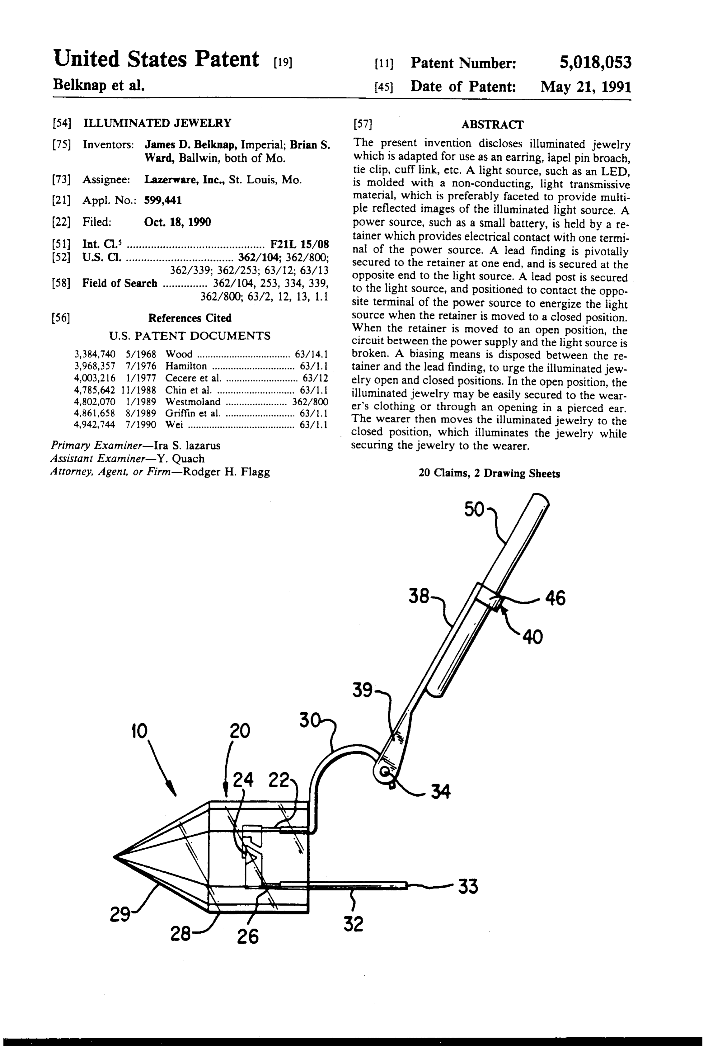
United States Patent (19) (11) Patent Number: 5,018,053 Belknap et al. (45) Date of Patent: May 21, 1991 (54) ILLUMINATED JEWELRY (57) ABSTRACT (75) Inventors: James D. Belknap, Imperial; Brian S. The present invention discloses illuminated jewelry Ward, Ballwin, both of Mo. which is adapted for use as an earring, lapel pin broach, tie clip, cufflink, etc. A light source, such as an LED, (73) Assignee: Lazerware, Inc., St. Louis, Mo. is molded with a non-conducting, light transmissive (21) Appl. No.: 599,441 material, which is preferably faceted to provide multi pie reflected images of the illuminated light source. A (22) Filed: Oct. 18, 1990 power source, such as a small battery, is held by a re 51) Int. Cl. .............................................. F21L 15/08 tainer which provides electrical contact with one termi 52 U.S. Cl. .................................... 362/104; 362/800; nal of the power source. A lead finding is pivotally secured to the retainer at one end, and is secured at the 362/339; 362/253; 63/12; 63/13 opposite end to the light source. A lead post is secured 58) Field of Search ............... 362/104, 253, 334, 339, to the light source, and positioned to contact the oppo 362/800; 63/2, 12, 13, 1.1 site terminal of the power source to energize the light (56) References Cited source when the retainer is moved to a closed position.
circuit between the power supply and the light source is 3,384,740 5/1968 Wood ................................... 63/14.1 broken. A biasing means is disposed between the re
tainer and the lead finding, to urge the illuminated jew 4,785,642 11/1988 Chin et al. ............................. 63/1.
elry open and closed positions. In the open position, the 4,802,070 1/1989 Westmoland .... ... 362/800 illuminated jewelry may be easily secured to the wear 4,861,658 8/1989 Griffin et al. .......................... 63/1.1 er's clothing or through an opening in a pierced ear. 4,942,744 7/1990 Wei........................................ 63/1.1 The wearer then moves the illuminated jewelry to the closed position, which illuminates the jewelry while
Primary Examiner-Ira S. lazarus securing the jewelry to the wearer. Assistant Examiner-Y. Quach
Attorney, Agent, or Firm-Rodger H. Flagg 20 Clains, 2 Drawing Sheets
Page 2
Drawing sheet — no readable text.
Page 3
Drawing sheet — no readable text.
Page 4
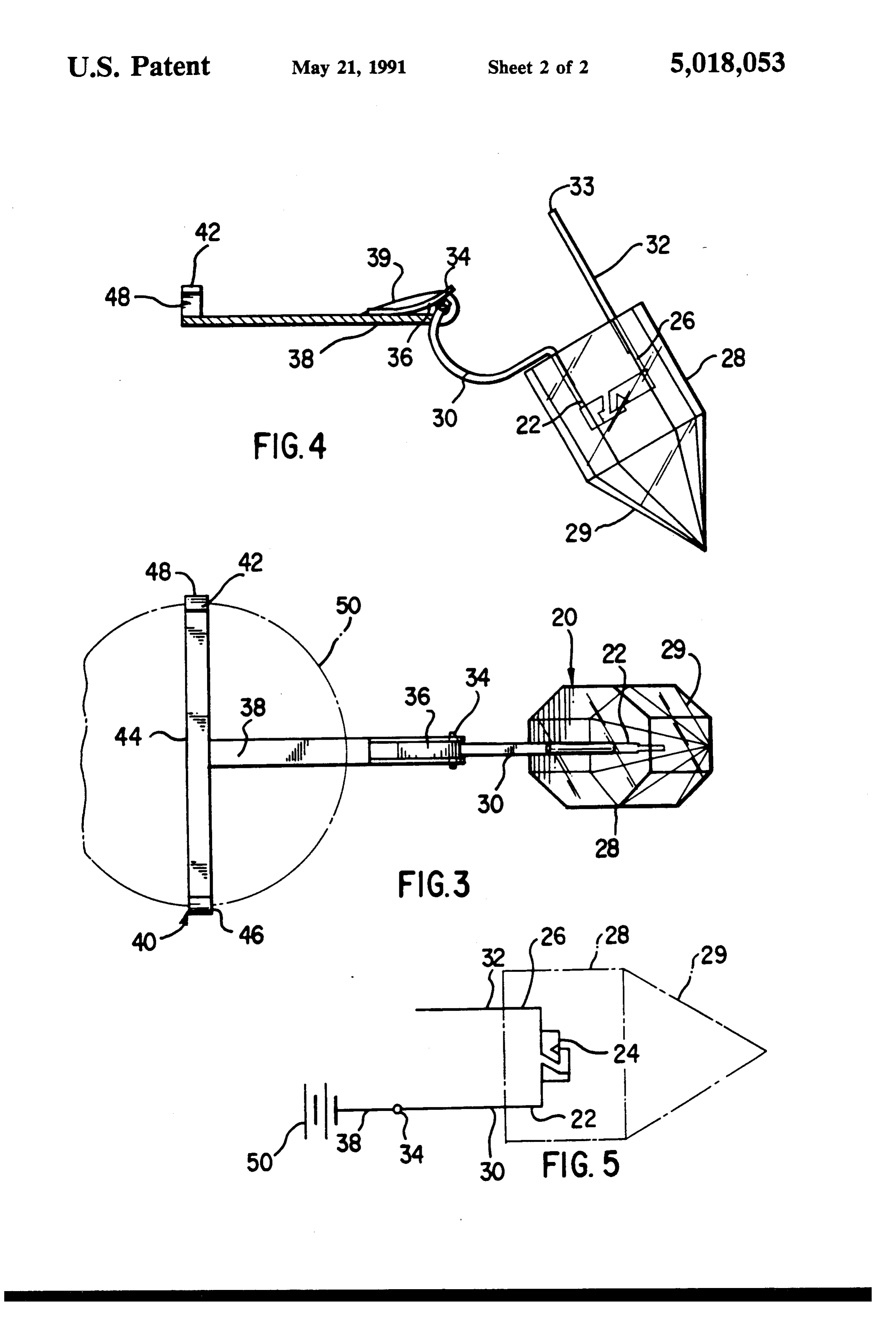
FIG. 4 is a sectional view of the retainer, showing the
ILLUMINATED JEWELRY preferred leaf spring.
FIG. 5 is a schematic diagram showing the electrical
BACKGROUND OF THE INVENTION circuitry of the invention.
This invention relates to improvements in illuminated 5 BEST MODE FOR CARRYING OUT THE jewelry, for the purpose of adornment, and more partic INVENTION ularly to earrings, lapel pins, broaches, tie clips, cuff The subject matter which I regard as my invention is links and other types of illuminated jewelry. A light particularly source, such as an LED, is molded within a light trans 10 claims. The pointed out and distinctly claimed in the structure and operation of my invention, mittable material, which is preferably faceted to pro together with further objects and advantages, may be vide multiple reflected images of the light source when better understood from the following description given illuminated.
Illuminated jewelry has been known in the art for in connection with the accompanying drawings, in which:
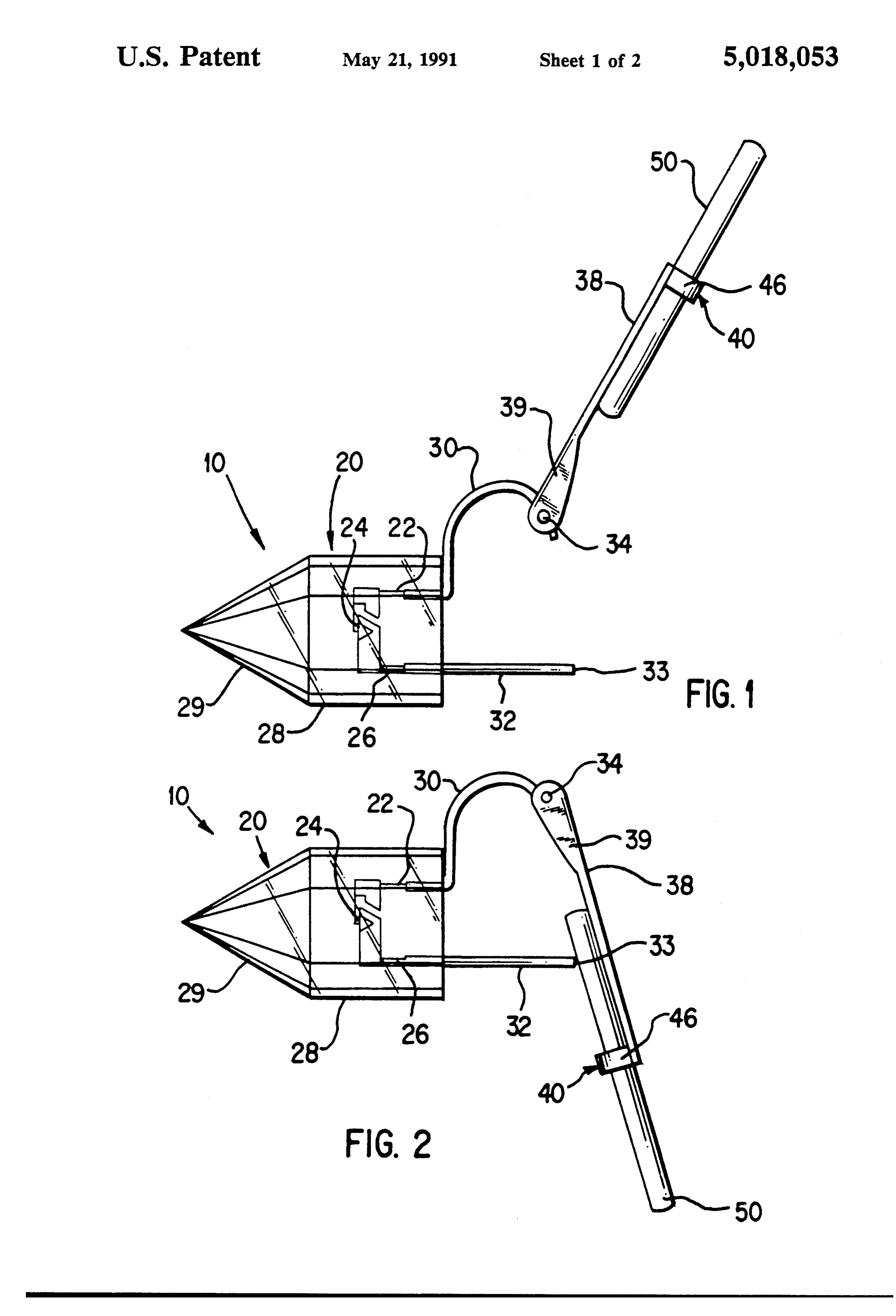
some time, which requires a variety of screws, clamps 15 FIG. 1 shows a side view of the illuminated jewelry or other mechanisms for securing the illuminated jew 10, having a light transmissive, non-conducting material elry to the user. Examples include U.S. Pat. Nos. 20 which encapsulates a light source 24, such as a light 4,791,536 and 3,968,357. emitting diode, (LED), having first and second electri Many of these prior art devices include separable cally conducting leads 22, 26 extending from the light parts which may become lost or misplaced, which will 20 source 24.
render the jewelry non-illuminating, if lost. Examples The light source 24, may be selected from a variety of include U.S. Pat. Nos. 4,802,070 and 4,337,504. known light emitting elements, having various sizes, Other prior art devices require an independent switch shapes, colors and voltages. Preferably the light source means to actuate the illuminated jewelry. Examples 24 provides a low voltage, high intensity colored light include U.S. Pat. Nos. 4,408,261; 4,719,544; 3,624,384 25 of small size suitable for encapsulation within the light and 3,384,740. transmissive material 20. The light source 24 should be U.S. Pat. No. 4,337,504 discloses an electronic ear long lasting and selected to not excessively drain the ring having a conductive post for passing through an power supply 50. A light emitting diode (LED) is the opening in the user's ear, wherein the battery must be 30 preferred light source.
removed from the jewelry to install or remove the de The light transmissive material 20 preferably has a vice on the user's ear. body portion 28, with a multi-faceted surface portion
SUMMARY OF THE INVENTION
29, which acts to reflect light from the light source 24 in a pattern simulating multiple light sources. The multi
The present invention discloses self contained, illumi 35 faceted surface portion 29 acts as a prism to reflect light nated jewelry comprising a battery engaging electri and heighten the effect of the illuminated jewelry 10. cally conductive retainer pivotally secured at one end The light transmissive material 20 may be transparent to a lead finding which is secured at the opposite end to or translucent, and may be colored with a pigment, dye a light source, such as a light emitting diode (LED) or other known coloring means or surface preparation encapsulated within a non-conducting, light transmit means to provide a colored light visually extending ting material. The light transmitting material is prefera from the illuminated jewelry 10. The light transmissive bly faceted to provide multiple light images from the material may be acrylic, glass or other known material light source when the light source is energized. A lead suitable for encapsulating the light source 24, while post extends from the encapsulated material to releas providing a non-conductive, light transmissive material 20 as disclosed herein.
ably secure the illuminated jewelry to the user's pierced 45 As shown in FIG. 1, the light transmissive material 20 ear lobe or clothing. The lead post connects to the light may be cast in any desired shape or pattern. Additional source at one end and engages the power source at the opposite end to energize the light source when the illu lightadapted diffracting design elements (not shown) may be for attachment to the encapsulated light source minated jewelry is in the closed position. 24, for enlargment or enhancement of the illuminated A biasing means, such as a leaf spring, is disposed 50 jewelry 10, or to create a desired artistic effect. The between the battery retainer and the lead finding ex addition or removal of additional tending from the light source. The leaf spring biases the change the outward appearance ofdesign the elements will illuminated jew illuminated jewelry between opened and closed posi elry, without affecting the circuitry or the operation of tions.
the illuminated jewelry 10.
The above mentioned and other features and objects 55 Referring now to FIG. 1, a conductive lead finding of the invention, and the manner of attaining them will 30 is secured at one end to lead 22 extending from the be best understood by reference to the following de light source 24. A conductive lead post 32 is secured at scription of an embodiment of the invention, when con one end to lead 26 extending from the light source 24. sidered in conjunction with the accompanying draw The lead post 32 serves as a mounting for the illumi lings: nated jewelry 10 to the wearer's pierced ear lobe or to BRIEF DESCRIPTION OF THE DRAWINGS a selected location on the wearer's clothing. Any means of securement, such as a solder connec
FIG. 1 is a side view of the illuminated jewelry, tion, may be used to provide electrical communication shown in open position. between lead 22 and lead finding 30 or lead 26 and lead FIG. 2 is a side view of the illuminated jewelry, 65 post 32. Where the means of securement may be toxic or shown in closed position. may irritate the skin, such as when solder is used, it is FIG. 3 is a top view of the illuminated jewelry, preferred to encapsulate the means of securement shown in the open position. within the light transmissive material 20, at the time the
Page 5
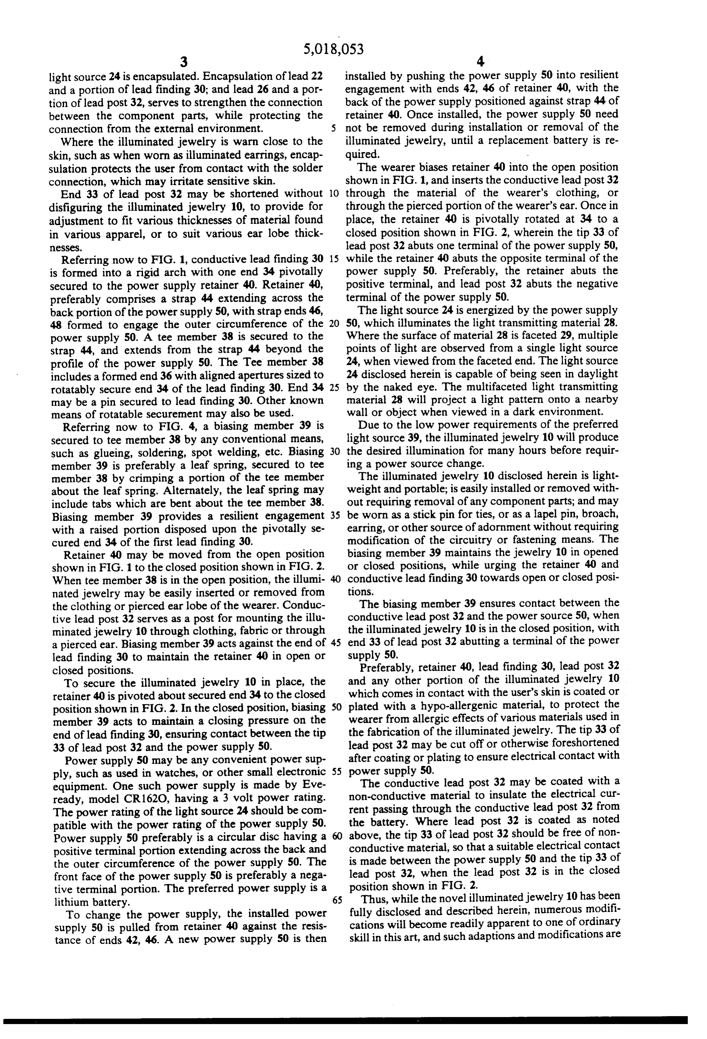
light source 24 is encapsulated. Encapsulation of lead 22 installed by pushing the power supply 50 into resilient and a portion of lead finding 30; and lead 26 and a por engagement with ends 42, 46 of retainer 40, with the tion of lead post 32, serves to strengthen the connection back of the power supply positioned against strap 44 of between the component parts, while protecting the retainer 40. Once installed, the power supply 50 need connection from the external environment. not be removed during installation or removal of the Where the illuminated jewelry is warn close to the illuminated jewelry, until a replacement battery is re skin, such as when worn as illuminated earrings, encap quired.
sulation protects the user from contact with the solder The wearer biases retainer 40 into the open position connection, which may irritate sensitive skin. shown in FIG. 1, and inserts the conductive lead post 32 End 33 of lead post 32 may be shortened without 10 through the material of the wearer's clothing, or disfiguring the illuminated jewelry 10, to provide for through the pierced portion of the wearer's ear. Once in adjustment to fit various thicknesses of material found place, the retainer 40 is pivotally rotated at 34 to a in various apparel, or to suit various ear lobe thick closed position shown in FIG. 2, wherein the tip 33 of esses. lead post 32 abuts one terminal of the power supply 50, Referring now to FIG. 1, conductive lead finding 30 15 while the retainer 40 abuts the opposite terminal of the is formed into a rigid arch with one end 34 pivotally power supply 50. Preferably, the retainer abuts the secured to the power supply retainer 40. Retainer 40, positive terminal, and lead post 32 abuts the negative preferably comprises a strap 44 extending across the terminal of the power supply 50. back portion of the power supply 50, with strap ends 46, The light source 24 is energized by the power supply 48 formed to engage the outer circumference of the 20 50, which illuminates the light transmitting material 28. power supply 50. A tee member 38 is secured to the Where the surface of material 28 is faceted 29, multiple strap 44, and extends from the strap 44 beyond the points of light are observed from a single light source profile of the power supply 50. The Tee member 38 24, when viewed from the faceted end. The light source includes a formed end 36 with aligned apertures sized to 24 disclosed herein is capable of being seen in daylight rotatably secure end 34 of the lead finding 30. End 34 25 by the naked eye. The multifaceted light transmitting may be a pin secured to lead finding 30. Other known material 28 will project a light pattern onto a nearby means of rotatable securement may also be used. wall or object when viewed in a dark environment. Referring now to FIG. 4, a biasing member 39 is Due to the low power requirements of the preferred secured to tee member 38 by any conventional means, light source 39, the illuminated jewelry 10 will produce such as glueing, soldering, spot welding, etc. Biasing 30 the desired illumination for many hours before requir member 39 is preferably a leaf spring, secured to tee ing a power source change.
member 38 by crimping a portion of the tee member The illuminated jewelry 10 disclosed herein is light about the leaf spring. Alternately, the leaf spring may weight and portable; is easily installed or removed with include tabs which are bent about the tee member 38. out requiring removal of any component parts; and may Biasing member 39 provides a resilient engagement 35 be worn as a stick pin for ties, or as a lapel pin, broach, with a raised portion disposed upon the pivotally se earring, or other source of adornment without requiring cured end 34 of the first lead finding 30. modification of the circuitry or fastening means. The Retainer 40 may be moved from the open position biasing member 39 maintains the jewelry 10 in opened shown in FIG. 1 to the closed position shown in FIG. 2. or closed positions, while urging the retainer 40 and When tee member 38 is in the open position, the illumi conductive lead finding 30 towards open or closed posi nated jewelry may be easily inserted or removed from tions.
the clothing or pierced ear lobe of the wearer. Conduc The biasing member 39 ensures contact between the tive lead post 32 serves as a post for mounting the illu conductive lead post 32 and the power source 50, when minated jewelry 10 through clothing, fabric or through the illuminated jewelry 10 is in the closed position, with a pierced ear. Biasing member 39 acts against the end of 45 end 33 of lead post 32 abutting a terminal of the power lead finding 30 to maintain the retainer 40 in open or supply 50.
closed positions. Preferably, retainer 40, lead finding 30, lead post 32 To secure the illuminated jewelry 10 in place, the and any other portion of the illuminated jewelry 10 retainer 40 is pivoted about secured end 34 to the closed which comes in contact with the user's skin is coated or position shown in FIG. 2. In the closed position, biasing 50 plated with a hypo-allergenic material, to protect the member 39 acts to maintain a closing pressure on the wearer from allergic effects of various materials used in end of lead finding 30, ensuring contact between the tip the fabrication of the illuminated jewelry. The tip 33 of 33 of lead post 32 and the power supply 50. lead post 32 may be cut off or otherwise foreshortened Power supply 50 may be any convenient power sup after coating or plating to ensure electrical contact with ply, such as used in watches, or other small electronic 55 power supply 50.
equipment. One such power supply is made by Eve The conductive lead post 32 may be coated with a ready, model CR 162O, having a 3 volt power rating. non-conductive material to insulate the electrical cur The power rating of the light source 24 should be com rent passing through the conductive lead post 32 from patible with the power rating of the power supply 50. the battery. Where lead post 32 is coated as noted Power supply 50 preferably is a circular disc having a above, the tip 33 of lead post 32 should be free of non positive terminal portion extending across the back and conductive material, so that a suitable electrical contact the outer circumference of the power supply 50. The is made between the power supply 50 and the tip 33 of front face of the power supply 50 is preferably a nega lead post 32, when the lead post 32 is in the closed tive terminal portion. The preferred power supply is a position shown in FIG. 2.
lithium battery. 65 Thus, while the novel illuminated jewelry 10 has been To change the power supply, the installed power fully disclosed and described herein, numerous modifi supply 50 is pulled from retainer 40 against the resis cations will become readily apparent to one of ordinary tance of ends 42, 46. A new power supply 50 is then skill in this art, and such adaptions and modifications are
Page 6
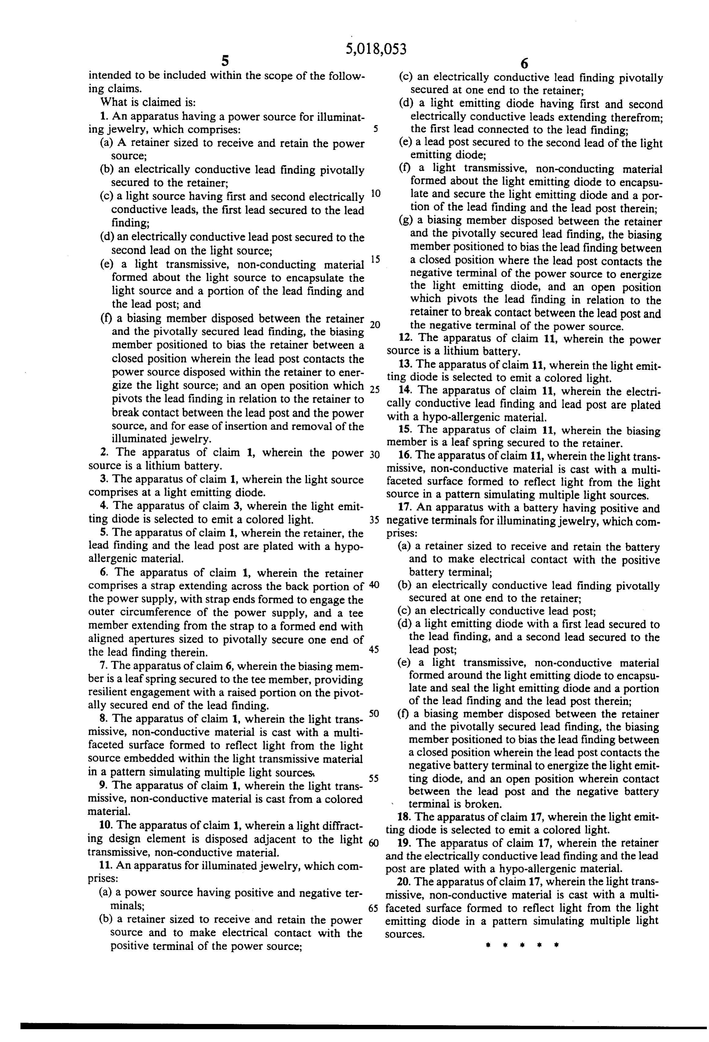
intended to be included within the scope of the follow (c) an electrically conductive lead finding pivotally ing claims. secured at one end to the retainer; What is claimed is: (d) a light emitting diode having first and second 1. An apparatus having a power source for illuminat electrically conductive leads extending therefrom; ing jewelry, which comprises: the first lead connected to the lead finding; (a) A retainer sized to receive and retain the power (e) a lead post secured to the second lead of the light Source; emitting diode;
(b) an electrically conductive lead finding pivotally (f) a light transmissive, non-conducting material secured to the retainer; formed about the light emitting diode to encapsu (c) a light source having first and second electrically 10 late and secure the light emitting diode and a por conductive leads, the first lead secured to the lead tion of the lead finding and the lead post therein; finding; (g) a biasing member disposed between the retainer (d) an electrically conductive lead post secured to the and the pivotally secured lead finding, the biasing second lead on the light source; member positioned to bias the lead finding between (e) a light transmissive, non-conducting material 15 a closed position where the lead post contacts the formed about the light source to encapsulate the negative terminal of the power source to energize light source and a portion of the lead finding and the light emitting diode, and an open position the lead post; and which pivots the lead finding in relation to the (f) a biasing member disposed between the retainer 20 retainer to break contact between the lead post and and the pivotally secured lead finding, the biasing the negative terminal of the power source. member positioned to bias the retainer between a source 12. The apparatus of claim 11, wherein the power closed position wherein the lead post contacts the is a lithium battery.
power source disposed within the retainer to ener ting diodeapparatus
of claim 11, wherein the light emit selected to emit a colored light.
gize the light source; and an open position which 25 14. The apparatus of claim 11, wherein the electri pivots the lead finding in relation to the retainer to cally conductive lead finding and lead post are plated break contact between the lead post and the power with a hypo-allergenic material.
source, and for ease of insertion and removal of the 15. The apparatus of claim 11, wherein the biasing illuminated jewelry. member is a leaf spring secured to the retainer. 2. The apparatus of claim 1, wherein the power 30 16. The apparatus of claim 11, wherein the light trans source is a lithium battery. missive, non-conductive material is cast with a multi 3. The apparatus of claim 1, wherein the light source faceted surface formed to reflect light from the light comprises at a light emitting diode. source in a pattern simulating multiple light sources. 4. The apparatus of claim 3, wherein the light emit 17. An apparatus with a battery having positive and ting diode is selected to emit a colored light. 35 negative terminals for illuminating jewelry, which com 5. The apparatus of claim 1, wherein the retainer, the prises:
lead finding and the lead post are plated with a hypo (a) a retainer sized to receive and retain the battery allergenic material. and to make electrical contact with the positive 6. The apparatus of claim 1, wherein the retainer battery terminal;
comprises a strap extending across the back portion of 40 (b) an electrically conductive lead finding pivotally the power supply, with strap ends formed to engage the secured at one end to the retainer; outer circumference of the power supply, and a tee (c) an electrically conductive lead post; member extending from the strap to a formed end with (d) a light emitting diode with a first lead secured to aligned apertures sized to pivotally secure one end of 45 the lead finding, and a second lead secured to the the lead finding therein. lead post;
7. The apparatus of claim 6, wherein the biasing men (e) a light transmissive, non-conductive material ber is a leaf spring secured to the tee member, providing formed around the light emitting diode to encapsu resilient engagement with a raised portion on the pivot late and seal the light emitting diode and a portion ally secured end of the lead finding. of the lead finding and the lead post therein; 8. The apparatus of claim 1, wherein the light trans 50 (f) a biasing member disposed between the retainer missive, non-conductive material is cast with a multi and the pivotally secured lead finding, the biasing faceted surface formed to reflect light from the light member positioned to bias the lead finding between source embedded within the light transmissive material a closed position wherein the lead post contacts the in a pattern simulating multiple light sources, negative battery terminal to energize the light emit 9. The apparatus of claim 1, wherein the light trans 55 ting diode, and an open position wherein contact missive, non-conductive material is cast from a colored between the lead post and the negative battery terminal is broken.
material.
10. The apparatus of claim 1, wherein a light diffract 18. The apparatus of claim 17, wherein the light emit ing design element is disposed adjacent to the light ting diode is selected to emit a colored light. transmissive, non-conductive material.
19. The apparatus of claim 17, wherein the retainer and the electrically conductive lead finding and the lead 11. An apparatus for illuminated jewelry, which con post are plated with a hypo-allergenic material. prises: 20. The apparatus of claim 17, wherein the light trans (a) a power source having positive and negative ter missive, non-conductive material is cast with a multi minals; 65 faceted surface formed to reflect light from the light (b) a retainer sized to receive and retain the power emitting diode in a pattern simulating multiple light source and to make electrical contact with the SOCeS.
positive terminal of the power source; h it is E
Provenance
- Collection
- Cited prior art
- Original PDF
- patentimages.storage.googleapis.com →
- Filed
- 1990-10-18
- Pages
- 6
- Method
- pdftotext (the PDF's own text layer) + pdftoppm 300dpi page scans
- Source
- Google Patents bibliographic record
- Granted
- 1991-05-21
- Inventors
- James D. Belknap; Brian S. Ward; Lazerware Inc
- Transcribed from
- patentimages.storage.googleapis.com →