patent · US5274536
Illumination cover for fluorescent lamp
28 December 1993
Page 1 — bibliographic record
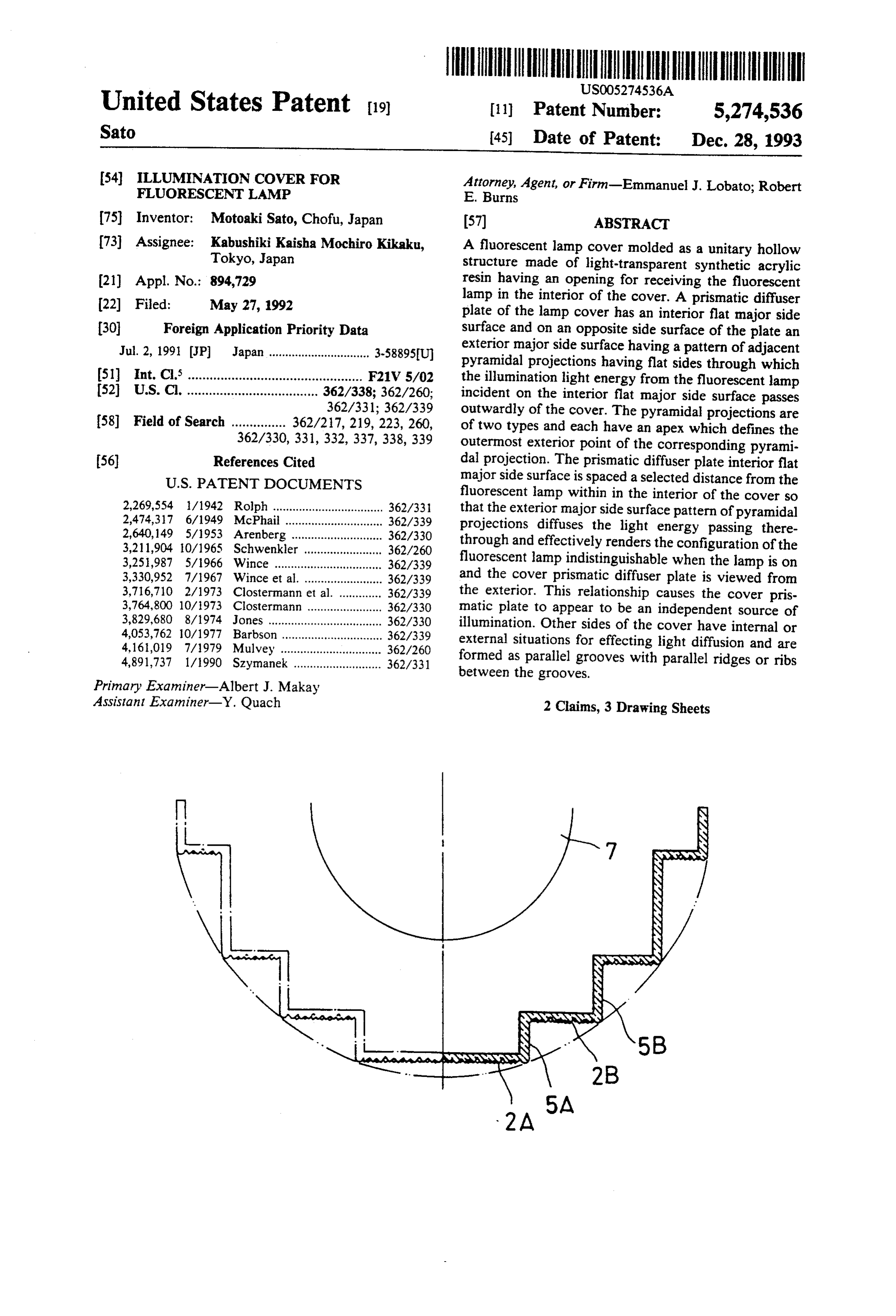
United States Patent (19) (11) Patent Number: 5,274,536 Sato (45) Date of Patent: Dec. 28, 1993 54). ILLUMINATION COVER FOR Attorney, Agent, or Firm-Emmanuel J. Lobato; Robert FLUORESCENT LAMP E. Burns (75) Inventor: Motoaki Sato, Chofu, Japan (57) ABSTRACT (73) Assignee: Kabushiki Kaisha Mochiro Kikaku, A fluorescent lamp cover molded as a unitary hollow Tokyo, Japan structure made of light-transparent synthetic acrylic (21) Appl. No.: 894,729 resin having an opening for receiving the fluorescent (22 Filed: May 27, 1992 lamp in the interior of the cover. A prismatic diffuser plate of the lamp cover has an interior flat major side 30 Foreign Application Priority Data surface and on an opposite side surface of the plate an Jul. 2, 1991 JP Japan ............................... 3-58895U) exterior major side surface having a pattern of adjacent pyramidal projections having flat sides through which 51) Int. Cl. ................................................ F21V 5/02 the illumination light energy from the fluorescent lamp 52 U.S. C. .................................... 362/338; 362/260; incident on the interior flat major side surface passes 362/331; 362/339 outwardly of the cover. The pyramidal projections are 58) Field of Search ............... 362/27, 219, 223, 260, of two types and each have an apex which defines the 362/330, 331, 332, 337, 338,339 outermost exterior point of the corresponding pyrami (56) References Cited dal projection. The prismatic diffuser plate interior flat
fluorescent lamp within in the interior of the cover so 2,269,554 1/1942 Rolph .................................. 362/33 that the exterior major side surface pattern of pyramidal 2,474,317 6/1949 McPhail ..... ... 362/339 projections diffuses the light energy passing there 2,640,149 5/1953 Arenberg ..... ... 362/330 through and effectively renders the configuration of the 3,211,904 10/1965 Schwenkler ..... ... 362/260 3,251,987 5/1966 Wince .............. ... 362/339 fluorescent lamp indistinguishable when the lamp is on 3,330,952 7/1967 Wince et al. ......... ... 362/339 and the cover prismatic diffuser plate is viewed from 3,716,710 2/1973 Clostermann et al. ... 362/339 the exterior. This relationship causes the cover pris 3,764,800 10/1973 Clostermann ........ ... 362/330 matic plate to appear to be an independent source of 3,829,680 8/1974 Jones ............ ... 362/330 illumination. Other sides of the cover have internal or 4,053,762 10/1977 Barbson ... 362/339 external situations for effecting light diffusion and are 4,161,019 7/1979 Mulvey ... ... 362/260 4,891,737 1/1990 Szymanek ........................... 362/331 formed as parallel grooves with parallel ridges or ribs between the grooves.
Primary Examiner-Albert J. Makay
Assistant Examiner-Y. Quach 2 Claims, 3 Drawing Sheets
Page 2
Drawing sheet — no readable text.

Page 3
Drawing sheet — no readable text.
Page 4
Drawing sheet — no readable text.
Page 5
LLUMINATION COVER FOR FLUORESCENT DESCRIPTION OF THE PREFERRED LAMP EMBODIMENTS
As illustrated in FIG. 1 a fluorescent lamp cover 1 can be constructed in various configurations and can be
Field of the Invention mounted overhead or on wall surfaces. FIG. 1 shows diagrammatically a railway car in which fluorescent
This invention relates generally to lamp covers and lamp covers 1 are mounted end-on-end overhead on the more particularly an illumination cover for a fluores ceiling of the railway car illustrated. These covers are cent lamp for use inside rooms and compartments of 10 of a rectangular configuration. The lamp cover 1 can railway cars and the like. also be constructed in an oval configuration and a rect Exposed light sources are generally optimal to use to angular configuration for wall mounting as shown dia obtain the maximum light energy from the light source. grammatically on the side walls of the railway car. Generally illumination devices are provided with a 15 The overhead light sources are provided with rectan cover for avoiding the danger of rupture of the lamp gular fluorescent lamp covers 1 as illustrated in FIG. 2 therein and the covers are frequently made so that they and the wall fluorescent lamps are recessed into the wall improve the appearance of the illumination device. and prismatic diffuser plates of the covers 1 provide the illumination surfaces on the walls for the interior of the
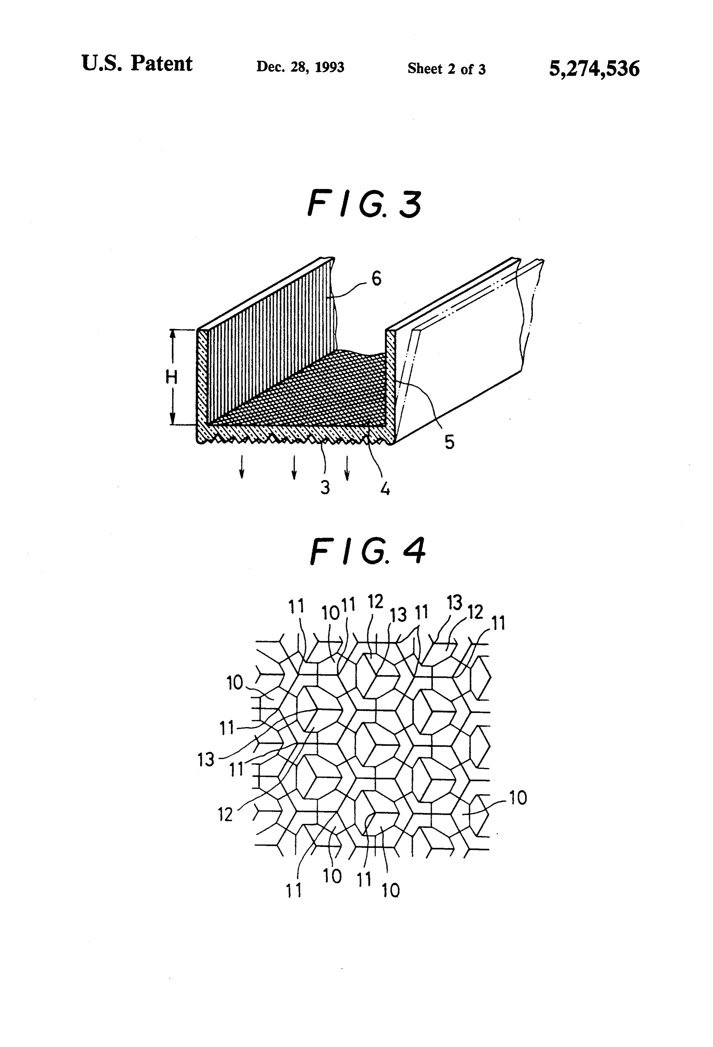
The light transmission factor of opal glass or frosted compartment glass light sources has been in the past in the order of of the railway car. 55%. When such lamps are used additional fluorescent The fluorescent lamp cover 1 illustrated in FIG. 2 is lamps and electric power necessary for the additional an integral unitary molded structure having a prismatic lamps is required because of the reduced illumination diffuser plate 2 having an exterior major surface 3 on factor of such devices. This results in substantially un which are formed pyramidal projections which func economical light sources. tion to diffuse the light energy incident on a flat inner
Furthermore the need of increase in fluorescent major surface 4 when the cover 1 is mounted over a lamps and fixtures results in an increase in weight in positefluorescent light. The fluorescent light cover 1 has op vehicles such as railway cars and increases cost in the gral with ends and sides 5 which are formed as plates inte manufacture thereof. the prismatic diffuser plate 2 defining a rectan gular cover.
SUMMARY OF THE INVENTION 30 The side plates 5 have internal striations 6 formed as The invention provides a highly efficient and eco The sidewhich grooves plates are parallel with a ridge therebetween.
5 have a height dimension H and are nomical illumination cover for fluorescent lamps. normal to the prismatic diffuser plate 2 in order to mini An object of the invention is to provide a fluorescent mize the visibility of the internal light source within the lamp cover which has a low loss of light and can be 35 cover and to render the striations or grooves 6 more readily produced by integral molding thereof with a effective in diffusing the light energy. simple mold of male and female molds without need of If the side plates 5 are not normal to the plane of the a split-cavity mold. internal major flat surface 4 and are inclined relatively Still another object of the present invention is to thereto, as illustrated in broken lines in FIG. 3, the provide a transparent prismatic diffuser plate structure striations 6 are less effective in diffusion of the light exhibiting the phenomenon of light diffusion such that energy from the internal light source and accordingly the lights source interiorly of the cover is more readily the fluorescent lamp light source can be rendered indis distinguishable.
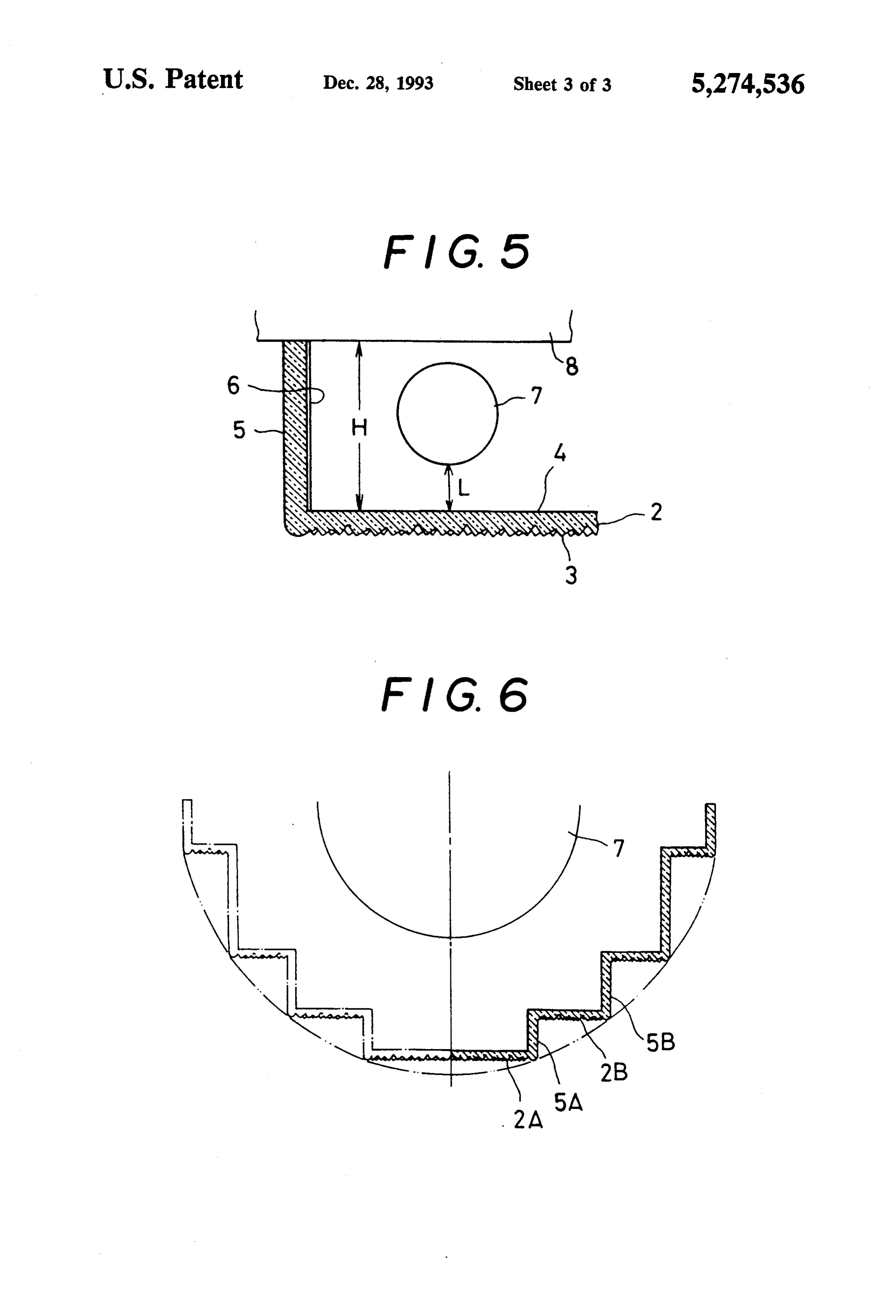
tinguishable from externally of the lamp by positioning the prismatic diffuser spaced a relatively short distance 45 The fluorescent light cover 1 illustrated in FIGS. 1 from the lamp to render the light source indistinguish and 2 have the plates 5 with the height dimension H able from the exterior and cause the prismatic diffuser such that a fluorescent light 7 made as a tube is spaced to function as an illumination surface. a distance L from the flat surface 4 when the cover is mounted on the fixture 8.
BRIEF DESCRIPTION OF THE DRAWINGS The light transparent prismatic plate 2 exhibits a phe The fluorescent lamp cover according to the inven SO nomenon such that the fluorescent lamp light source 7 tion is described herein and the appended claims and is becomes invisible and is not distinguishable as to its illustrated in the following drawings in which: configuration within the lamp cover when the lamp FIG. 1 is a diagrammatic perspective view of a rail cover is observed from the exterior of the prismatic way car illustrating the use of the fluorescent lamp 55 diffuser plate 2 and the entire surface of the prismatic diffuser plate appears as if it were a light emission sur cover device according to the invention; face. In order to obtain the phenomenal result the dis FIG. 2 is a perspective view of one embodiment of a tance L from the inner surface of the transparent pris fluorescent lamp cover according to the invention; matic diffuser plate has to be selected with reference to FIG. 3 is a fragmentary sectional view of the fluores the size of the prismatic projections, the refractive index cent lamp cover illustrated in FIG. 2;
FIG. 4 is a fragmentary plan view of a prismatic light 7. and thereof
This the size of the diameter of the fluorescent distance L is generally from about 16 to diffuser of the fluorescent lamp cover illustrated in about 20 millimeters and can readily be determined and FIG. 2; confirmed by easy experimentation. Since the fluores FIG. 5 is a fragmentary sectional view of a fluores cent lamp cover of the type illustrated in FIG. 2; and 65 cent lamp cover is an integral molded unitary structure made of a light transparent material such as synthetic
FIG. 6 is a fragmentary sectional view of another acrylic resin, the entire cover passes outwardly the light embodiment of a fluorescent lamp cover according to energy from the lamp. Light is reflected from a reflect the invention. ing plate 8 of the illumination device or fixture which
Page 6
supports the light source 7 thus the efficiency of light diffuser plate appears to be an independent illumination transmission is maximized. Furthermore the appearance SOCe.
of the light source is greatly improved over known Those skilled in the art will understand that the illum fluorescent lamp covers. ination cover for fluorescent lamps according to the In order to obtain the phenomenal light dispersion invention can be constructed in different configurations and cause the light transparent prismatic diffuser plate so long as the principles of the prismatic diffuser con to function as described above the prismatic diffuser struction are followed using the pyramidal projections surface 3 is constructed as illustrated in FIG. 4. This with flat sides arranged in accordance with the neces prismatic diffuser surface 3 is uneven but it does not 10 sary structure to effect the desired light diffusion. They will understand the pyramidal projections are not geo gather dust and dirt as generally gathered by known molded covers having a coarse surface. The prismatic metric prisms but have an effect of light diffusion re diffuser plate 2 is completely light transparent and ferred to herein as prismatic.
What I claim is:
makes it possible to obtain about 95% efficiency of the 1. A fluorescent lamp cover comprising a plurality of light power compared to an exposed light source. 5 light-transparent plates integrally joined defining a fluo The prismatic diffuser surface 3 utilized in the present rescent lamp cover having a length dimension for hous invention has a large number of molded triangular pyramids 10 on the outer surface of the transparent ing in an interior thereof a fluorescent lamp extending diffuser plate 2 made of molded synthetic resin. These ing an openingtherein, longitudinally said fluorescent lamp cover hav triangular pyramidal projections 10 are disposed rela 20 the interior thereof extendingthe for receiving
fluorescent lamp into the length dimension, tive to one another such that their pattern arrangement at least one of said light-transparent plates constituting a has the apexes 11 thereof positioned at the corners of prismatic diffuser plate having an interior flat major side equilateral hexagons as shown in FIG. 4. A second type surface on which light energy from said fluorescent of triangular pyramid or pyramidal projections 12 hav lamp is incident when the fluorescent lamp is on and ing apexes 13 are positioned at the center of recesses 25 said prismatic diffuser plate having an exterior major defined by the second type of triangular pyramids. The side surface opposite to said interior flat major side bases of the pyramids are contiguous and the sides are surface on which is disposed a pattern of adjacent pyra flat as shown in FIG. 4. This type of surface is itself midal projections through which the light energy known in the prior art (Japanese Utility Model Publica passes, each projection having an apex defining an out tion Nos. 42558/1979 and 29284/1984). This pattern of 30 ermost point of each corresponding projection, and said flat-sided pyramidal projections having the correspond interior flat major side surface being disposed spaced ing apex of each projection as the corresponding remote from the fluorescent lamp a selected distance within the point, of the prismatic diffuser plate 2, from the fluores fluorescent lamp cover effective in conjunction with cent lamp light 7 exhibits the desired phenomenon of said pattern of pyramidal projections to render indistin the prismatic diffuser surface to appear to be an inde 35 guishable the configuration of a fluorescent lamp within pendent illumination surface itself and through which the fluorescent lamp cover when the fluorescent lamp is the light outline source in the interior cannot be distin on and the fluorescent lamp cover is viewed looking at guished. The light configuration cannot be seen as is the prismatic diffuser plate from externally thereof, said possible in the known fluorescent light covers when the tionalfluorescent lamp cover including a plurality of addi cover is viewed. prismatic diffuser plates constructed similarly to a The striations on the side plates are illustrated as first-mentioned prismatic plate and facing exteriorly of formed in the interior surfaces of the side plates, how said fluorescent lamp cover in a same direction, and ever, they can be likewise formed on the outer surfaces each from additional prismatic diffuser plate being spaced said fluorescent lamp a corresponding selected of the side plates or on both the inner and outer surfaces 45 distance to render indistinguishable the configuration of when the unitary structure is molded of the cover. a fluorescent lamp within the fluorescent lamp cover The fluorescent light cover may be constructed as when the fluorescent lamp is on and the fluorescent illustrated in FIG. 6 in which a plurality of transparent lamp cover is viewed externally thereoflooking toward prismatic diffuser plates 2 are disposed in a stepped arrangement as shown. In this arrangement the pris 50 said2. prismatic diffuser plates. matic diffuser plates 2A, 2B have related side plates 5A, whichA all fluorescent lamp cover according to claim 1, in prismatic diffuser plates extend lengthwise in 5B arranged integrally so that the prismatic diffuser a same direction plates are held arranged in stepped parallel planes as direction in parallelandplanes are spaced in a circumferential about said fluorescent lamp shown. This type of cover construction is effective in positions to render indistinguishable the configura when the fluorescent lamps being used have small diam 55 eters and can be juxtaposed relative one to the other or tion
of the fluorescent lamp when the fluorescent lamp and the fluorescent lamp cover is viewed looking when the light source 7 has a large diameter as illus toward said prismatic diffuser plates from externally trated. In this embodiment the distance L of each of the thereof and to render the prismatic diffuser plates to prismatic diffuser plates, for example 2A, 2B, is main appear to be independent illumination source. tained relative to the light source 7. Each prismatic
Provenance
- Collection
- Cited prior art
- Original PDF
- patentimages.storage.googleapis.com →
- Filed
- 1992-05-27
- Pages
- 6
- Method
- pdftotext (the PDF's own text layer) + pdftoppm 300dpi page scans
- Source
- Google Patents bibliographic record
- Granted
- 1993-12-28
- Inventors
- Motoaki Sato; Mochiro Kikaku KK
- Transcribed from
- patentimages.storage.googleapis.com →