patent · US5037518
Apparatus and method for generating hydrogen and oxygen by electrolytic dissociation of water
6 August 1991
Page 1 — bibliographic record
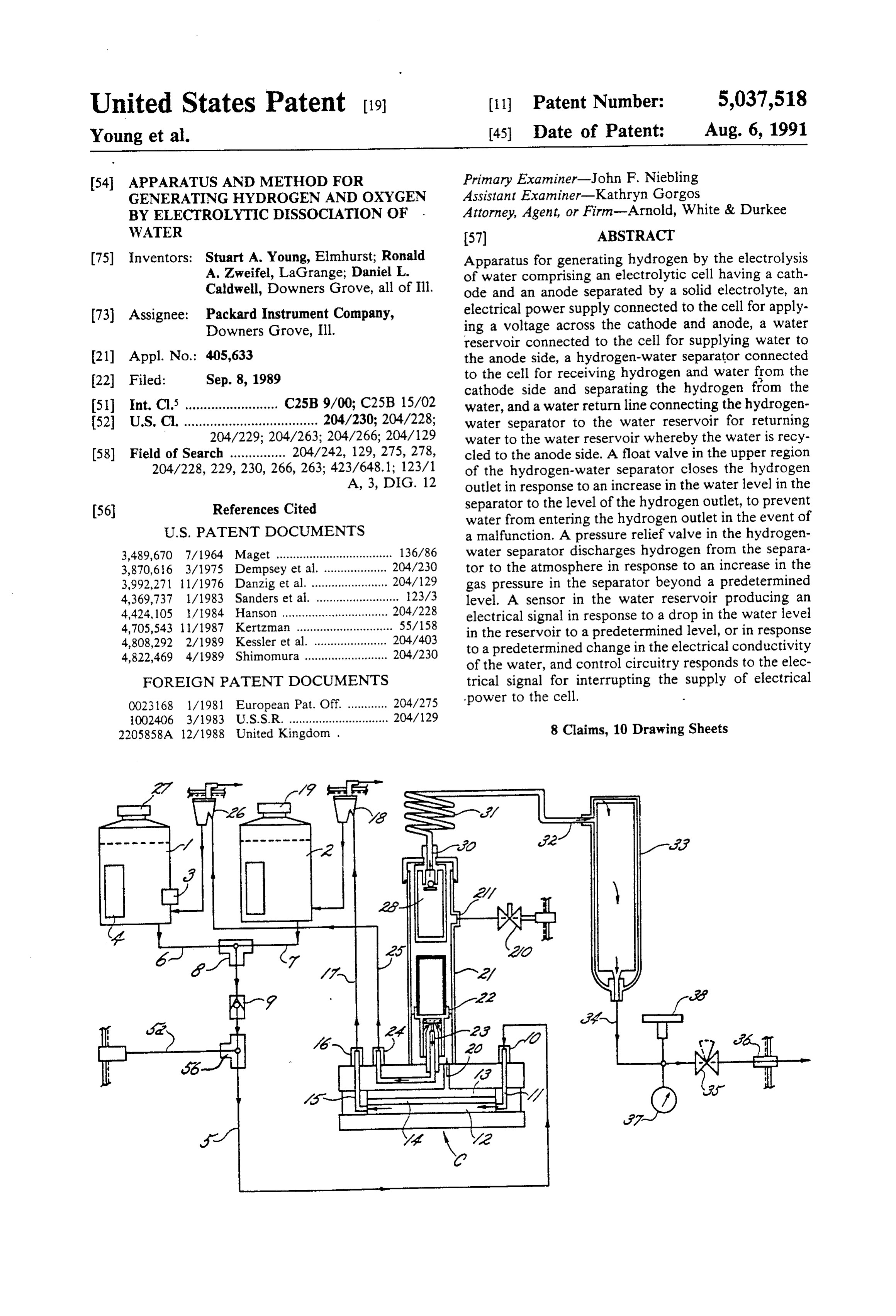
United States Patent (19) 11 Patent Number: 5,037,518 Young et al. 45 Date of Patent: Aug. 6, 1991 (54) APPARATUS AND METHOD FOR Primary Examiner-John F. Niebling GENERATING HYDROGEN AND OXYGEN Assistant Examiner-Kathryn Gorgos BY ELECTROLYTIC DISSOCATION OF . Attorney, Agent, or Firm-Arnold, White & Durkee WATER (57) ABSTRACT 75) Inventors: Stuart A. Young, Elmhurst; Ronald Apparatus for generating hydrogen by the electrolysis A. Zweifel, LaGrange; Daniel L. of water comprising an electrolytic cell having a cath Caldwell, Downers Grove, all of Ill. ode and an anode separated by a solid electrolyte, an 73) Assignee: Packard Instrument Company, electrical power supply connected to the cell for apply Downers Grove, Ill. ing a voltage across the cathode and anode, a water reservoir connected to the cell for supplying water to 21 Appl. No.: 405,633 the anode side, a hydrogen-water separator connected 22 Filed: Sep. 8, 1989 to the cell for receiving hydrogen and water from the cathode side and separating the hydrogen from the 51) Int. Cl. ......................... C25B 9/00; C25B 15/02 water, and a water return line connecting the hydrogen 52 U.S. C. .................................... 204/230; 204/228; water separator to the water reservoir for returning 204/229; 204/263; 204/266; 204/129 water to the water reservoir whereby the water is recy 58) Field of Search ............... 204/242, 129, 275, 278, cled to the anode side. A float valve in the upper region 204/228, 229, 230, 266, 263; 423/648.1; 123/1 of the hydrogen-water separator closes the hydrogen A, 3, DIG. 12 outlet in response to an increase in the water level in the (56) References Cited separator to the level of the hydrogen outlet, to prevent water from entering the hydrogen outlet in the event of
3,489,670 7/1964 Maget ................................... 136/86 water separator discharges hydrogen from the separa 3,870,616 3/1975 Dempsey et al... ... 204/230 tor to the atmosphere in response to an increase in the 3,992,271 l1/1976 Danzig et al....... . . 204/129 gas pressure in the separator beyond a predetermined 4,369,737 1/1983 Sanders et al. ......................... 123/3 level. A sensor in the water reservoir producing an 4,424, 105 l/1984 Hanson ........... ... 204/228 electrical signal in response to a drop in the water level 4,705,543 l l/1987 Kertzman ............................. 55/158 in the reservoir to a predetermined level, or in response 4,808,292 2/1989 Kessler et al. ...................... 204/403 to a predetermined change in the electrical conductivity 4,822,469 4/1989 Shimomura ......................... 204/230 of the water, and control circuitry responds to the elec FOREIGN PATENT DOCUMENTS trical signal for interrupting the supply of electrical 0023168 1/1981 European Pat. Off............. 204/275 power to the cell.
1002406 3/1983 U.S.S.R. .............................. 204/129 2205858A 12/1988 United Kingdom . 8 Claims, 10 Drawing Sheets
Page 2
Drawing sheet — no readable text.
Page 3
Drawing sheet — no readable text.
Page 4
Drawing sheet — no readable text.
Page 5
Drawing sheet — no readable text.
Page 6
Drawing sheet — no readable text.
Page 7
Drawing sheet — no readable text.
Page 8
Drawing sheet — no readable text.
Page 9
Drawing sheet — no readable text.
Page 10
Drawing sheet — no readable text.
Page 11
Drawing sheet — no readable text.
Page 12
limited by the rate of water diffusing lack across the
APPARATUS AND METHOD FOR GENERATING membrane.
HYDROGEN AND OXYGEN BY ELECTROLYTIC “Drying out" or "breaking down" the membrane is a DISSOCATION OF WATER phenomenon which occurs when the electrolytic cell's demand for water is greater than the supply. The disso
BACKGROUND OF THE INVENTION ciation of water is driven by the current supplied to the electrolytic cell. As the current is increased, the quan 1. Field of the Invention tity of water dissociated is increased. However, if the The present invention relates to methods and appara supply of water at the anode is not great enough to tus for the generation of gases. More particularly, the 10 satisfy the demand of the electrolytic cell, the water present invention relates to methods and apparatus for molecules which were incorporated into the structure the generation of hydrogen and oxygen by the electro of the membrane during the manufacturing process will lytic dissociation of water. become dissociated. This irreversibly "dries out' the 2. Description of the Prior Art membrane, breaking down the polymer structure. As a It is well known that a gas, such as oxygen, hydrogen 15 result the output of the cell is progressively reduced, or chlorine, may be generated by disassociating a chem and the cell eventually becomes inoperable. This phe ical compound into its constituent elements. The prior nomenon will also occur if the generator accidentally art describes several devices which utilize electrolytic runs dry, or loses its water through a leak in the system, cells for disassociating such compounds and generating or if the solenoid valve remains closed indefinitely. gas. Such electrolytic cells take a variety of forms, but 20 The water contained in an electrolytic cell gas gener generally include a catalytic anode, a catalytic cathode ator can become contaminated with impurities, such as and an adjacent electrolyte which is in electrical metals, salts, acids, bases, or other electrolytes. Impuri contact with both the anode and the cathode. A d-c ties such as these are contained in ordinary tap water. voltage is applied across the catalytic electrodes to Once entered into the system, these impurities or con taminants are absorbed directly into the ion-exchange
When reactants contact an electrode, they are disso membrane, thereby "poisoning' the membrane and ciated into their constituent ionic forms, and the reducing the amount of uncontaminated surface area remaining to transport ions. As a result, the output of evolved gas is collected. For example, if water is placed the cell is progressively in contact with the anode, an oxidation reaction will 30 function entirely. This canreduced until the cell ceases to occur, disassociating the water to produce hydrogen amount of contamination beis agreat gradual processor, if the and oxygen ions. The hydrogen ions move to the cath brane can be poisoned in a matter ofenough, the mem ode where a reduction reaction produces hydrogen these contaminants are invisible to minutes. an Because operator and molecules, and at the anode the oxygen ions combine to electrolytic gas cell generators presently cannot detect form molecular oxygen. Generally, the electrolyte is a 35 if contaminated water is present, the ion-exchange solid polymeric ion-exchange membrane.
Gas generators employing electrolytic cells may be membranes of these systems can be destroyed by the used in many applications in place of compressed gas the generator. of tap water or other impure water into errant addition stored in cylinders. Moreover, electrolytic cells make possible the manufacture of inexpensive, compact de SUMMARY OF THE INVENTION vices for producing gas at the point of use. An example It is an object of the present invention to address one of an electrolytic cell gas generator is described in or more of the foregoing deficiencies in electrolytic gas Dempsey et al. U.S. Pat. No. 3,870,616, which describes generators by providing an improved electrolytic gas a hydrogen generator having a main water tank supply generator.
ing water to the anode of an electrolytic cell for dissoci 45 One particular object of the present invention is to ation. However, not all the water supplied to the anode provide an electrolytic hydrogen and oxygen generator is dissociated. In fact, the bulk of the water supplied to which produces hydrogen and oxygen at rates greater the anode is transported with the dissociated hydrogen than those attainable in presently available electrolytic ions across the ion-exchange membrane into the cath hydrogen generators.
ode chamber. Part of this water returns to the anode 50 Another important object of the present invention is chamber by diffusion back across the ion-exchange to provide an electrolytic gas generator which is con membrane; however, when gas is being actively gener structed to provide a longer productive lifetime for the ated, the rate of protonic pumping by the hydrogen ions ion-exchange membrane.
is much greater than the diffusion rate of the water back A further important object of the present invention is across the membrane so that eventually a build up of 55 to provide a electrolytic cell gas generator which in water takes place in a accumulator chamber disposed cludes various safety features which protect the electro above the cathode chamber. Whenever the water in the lytic cell from damage due to massive leaks, through the accumulator chamber rises above a predetermined errant addition of impure water, or due to the absence level, a solenoid valve is closed to shut off the water of water from the supply system.
supply from the main tank to the anode chamber. Nev 60 A still further object of the present invention is to ertheless, as long as there is an electrical current sup provide a electrolytic gas generator having a solid plied to the electrolytic cell, the dissociation reaction polymer-electrolyte electrolysis unit wherein the solid continues. In order to continue the reaction, and the polymer-electrolyte is protected from drying out. production of gas, water must be supplied to the anode. Other objects and advantages of the invention will be However, the only water supplied to the anode cham 65 apparent from the following detailed description and ber comes from the diffusion of water from the cathode the accompanying drawings.
chamber back across the ion-exchange membrane. Dur In accordance with the present invention, the forego ing this period, the dissociation of the water is rate ing objectives are realized by providing an electrolytic
Page 13
hydrogen and oxygen generator comprising an electro While the invention is susceptible to various modifi lytic cell having a cathode and an anode separated by an cations and alternative forms, specific embodiments electrolyte; an electrical power supply connected to the thereof have been shown by way of example in the electrolytic cell for applying a voltage across the cath drawings and will be described in detail herein. It ode and anode; a water reservoir connected to the elec should be understood, however, that it is not intended trolytic cell for supplying water to the anode side of the to limit the invention to the particular forms disclosed, cell; a hydrogen-water separator connected to the elec but on the contrary, the intention is to cover all modifi trolytic cell for receiving hydrogen and water from the cations, equivalents, and alternatives falling within the cathode side of the cell and separating the hydrogen spirit and scope of the invention as defined by the ap from the water; and a water return line connecting the O pended claims.
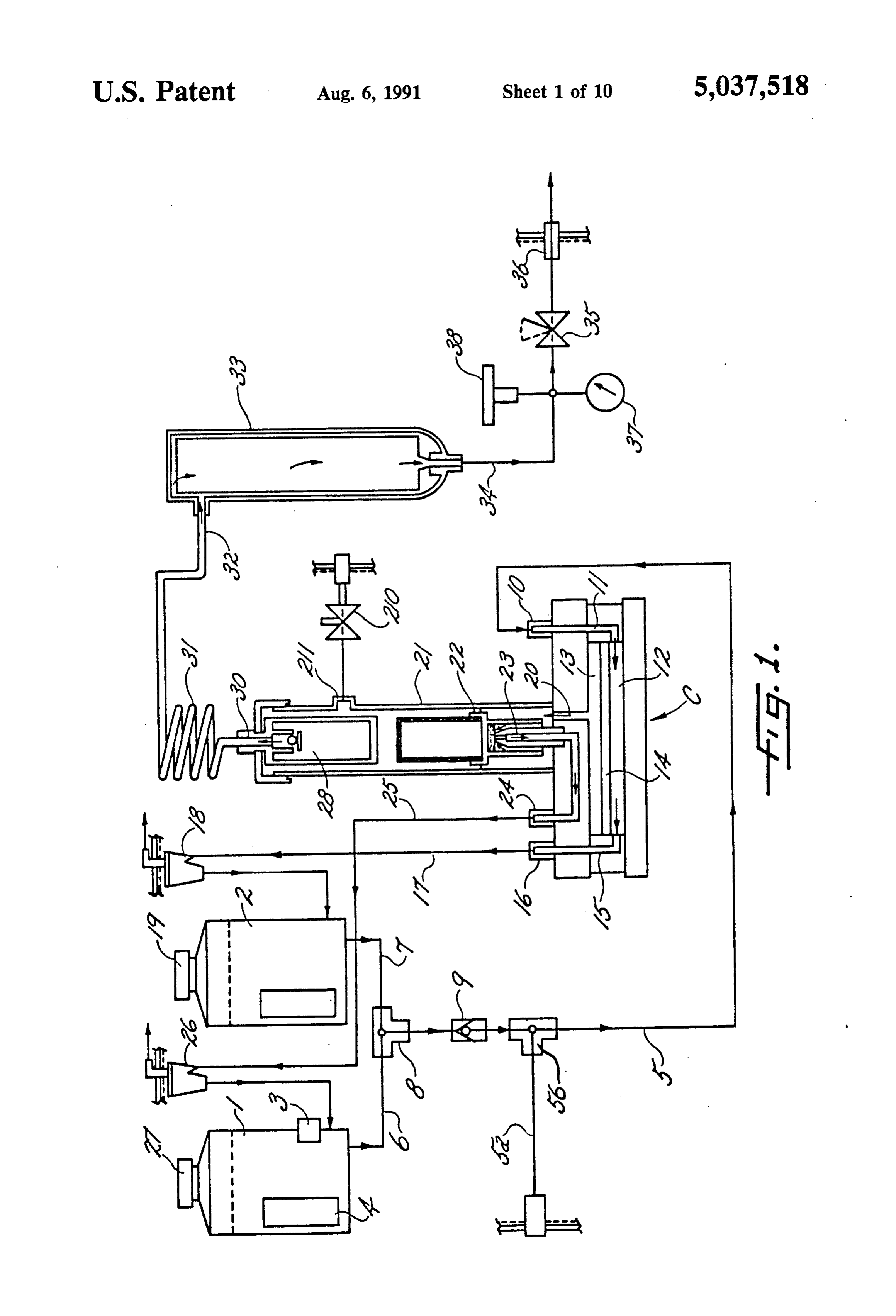
hydrogen-water separator to the water reservoir for DESCRIPTION OF THE PREFERRED returning water from the separator to the water reser EMBODIMENT voir so that the water is recycled to the anode side of said electrolytic cell. In a preferred embodiment, the 5 Turning now to the drawings and referring first to FIG. 1, there water reservoir includes a sensor for producing an elec hydrogen and oxygen byis shown a gas generator which produces trical signal in response to a drop in the water level in distilled water in an electrolyticthe electrolysis of deionized, the reservoir to a predetermined level or in response to cell C. Deionized, dis a predetermined change in the electrical conductivity of tilled water is the only liquid contained in the apparatus, the water in the reservoir, and control means responsive and tors must be replenished as it is consumed. Gas genera of this type are intended for use in gas chromatog to the electrical signal from the sensor for interrupting raphy, flame ionization detectors, sulfur monitors, and the supply of electrical power to the electrolytic cell. other equipment requiring a source of pure hydrogen. The preferred embodiment also includes a hydrogen output line for removing the hydrogen from the hydro is stored in reservoirs 1water
Deionized, distilled for the electrolysis process and 2. The reservoir 1 includes gen-water separator, the hydrogen output line including 25 a sensor 3 for simultaneously sensing both the presence a drying tube made of material which selectively ad and the purity of water in the reservoir, as will be de sorbs water vapor from gas flowing through the interior scribed in more detail below. If the sensor 3 detects of the tube, and transfers the adsorbed water to the either an inadequate water supply or impure water, it exterior of the tube. produces a signal which automatically interrupts the BRIEF DESCRIPTION OF THE DRAWINGS supply of electrical power to the cell C. This prevents In the drawings: damage to the electrolytic cell because supplying elec trical power to the cell without an adequate supply of
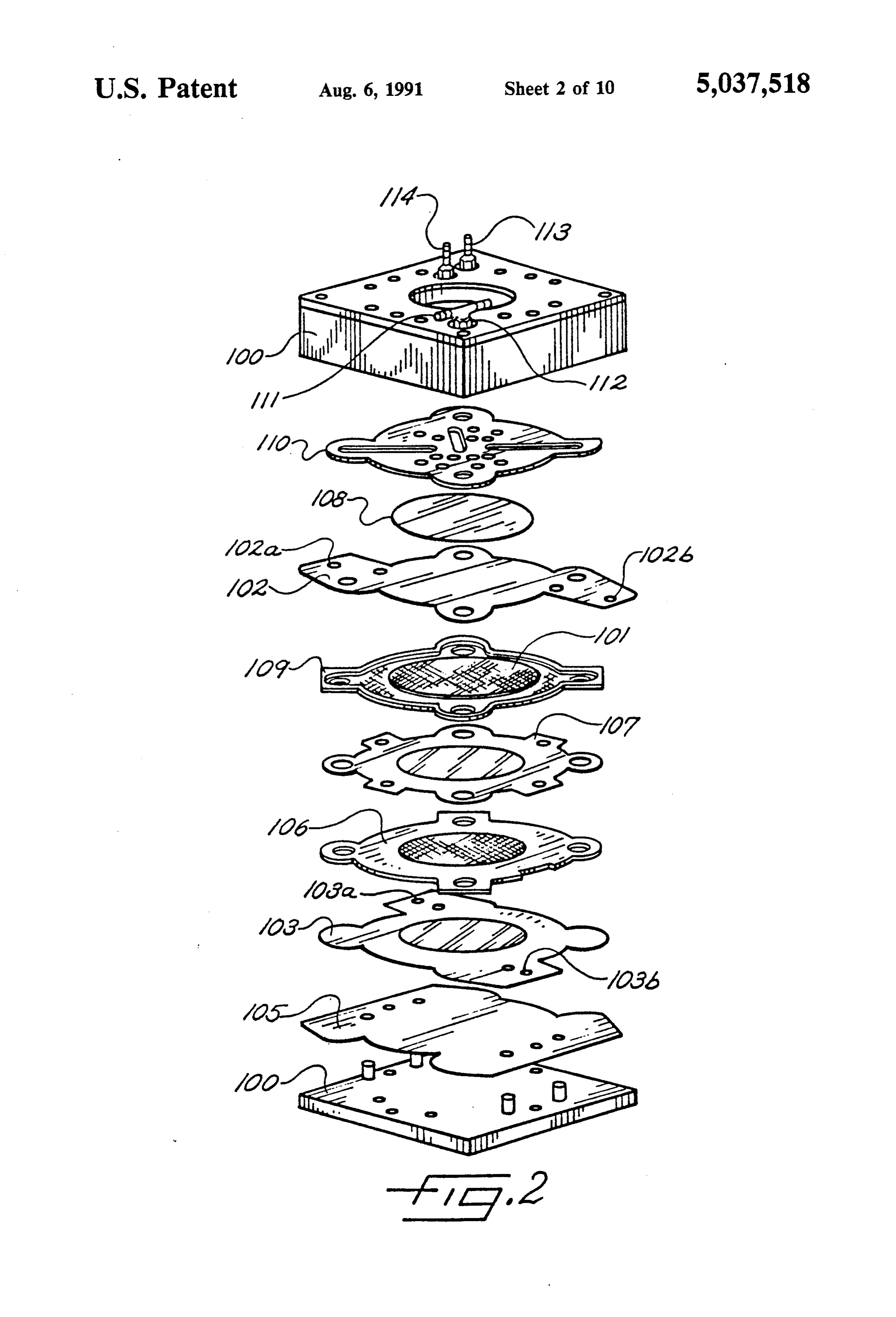
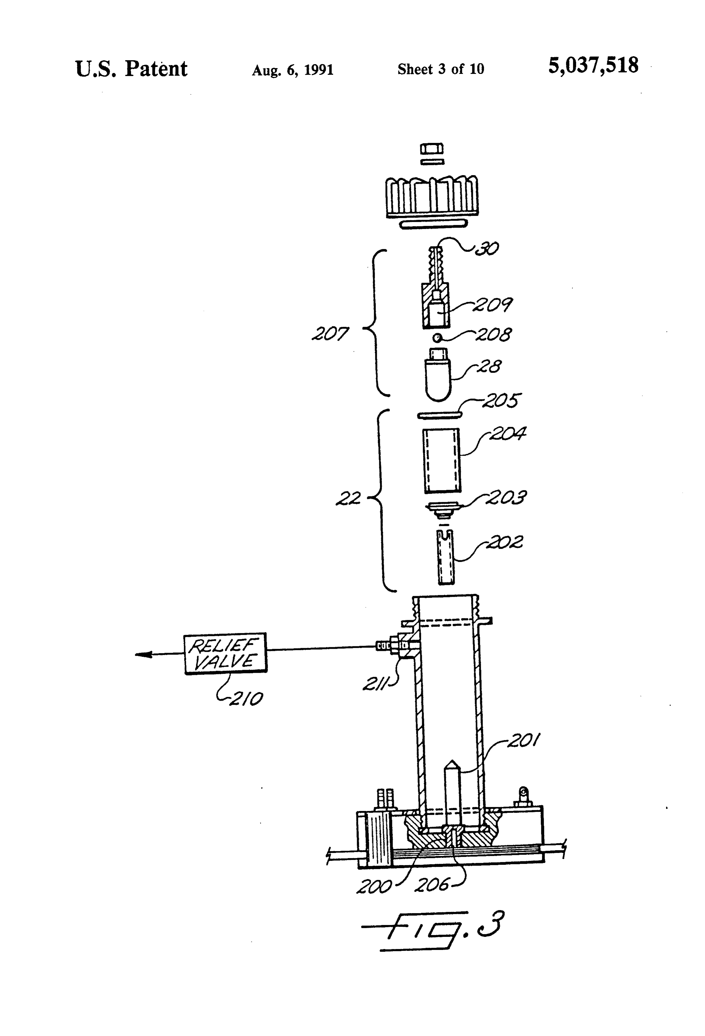
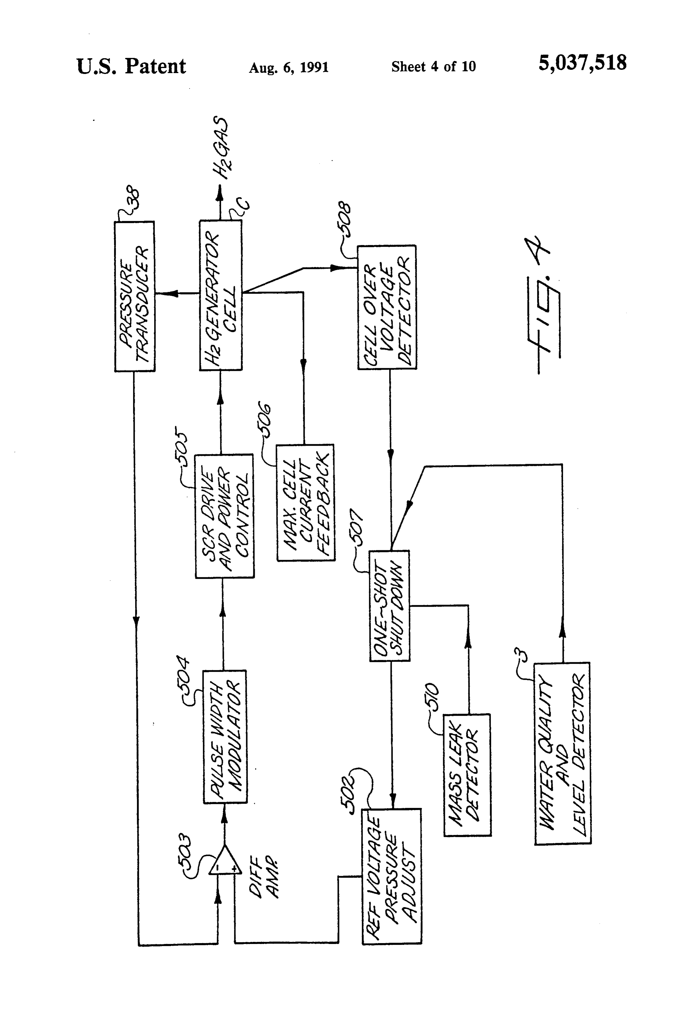
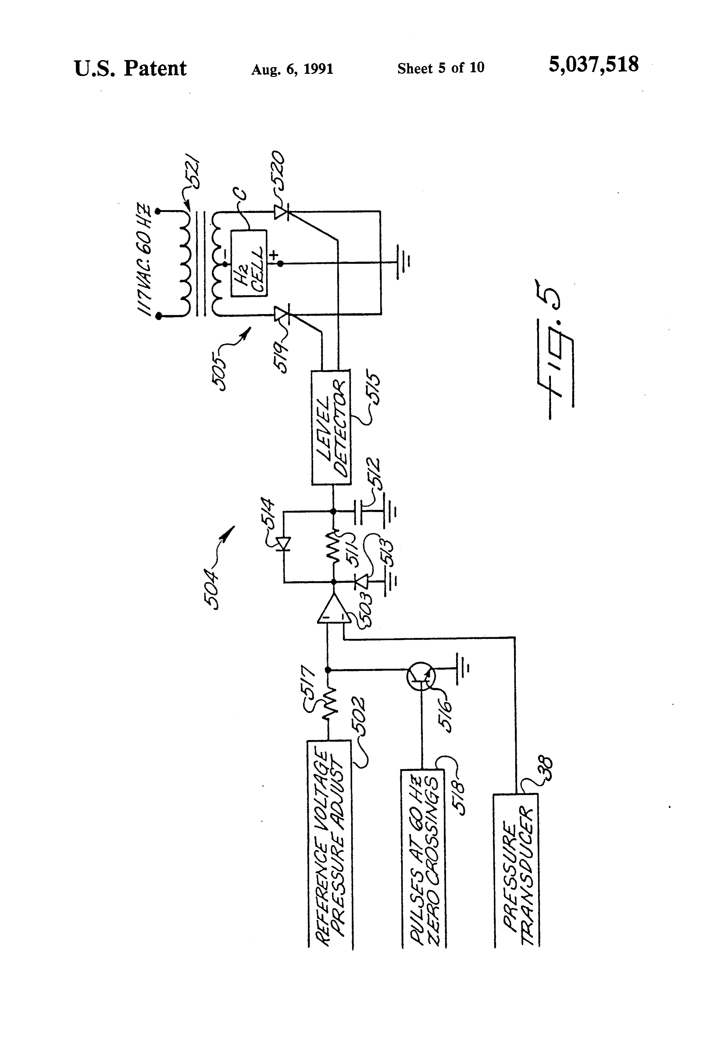
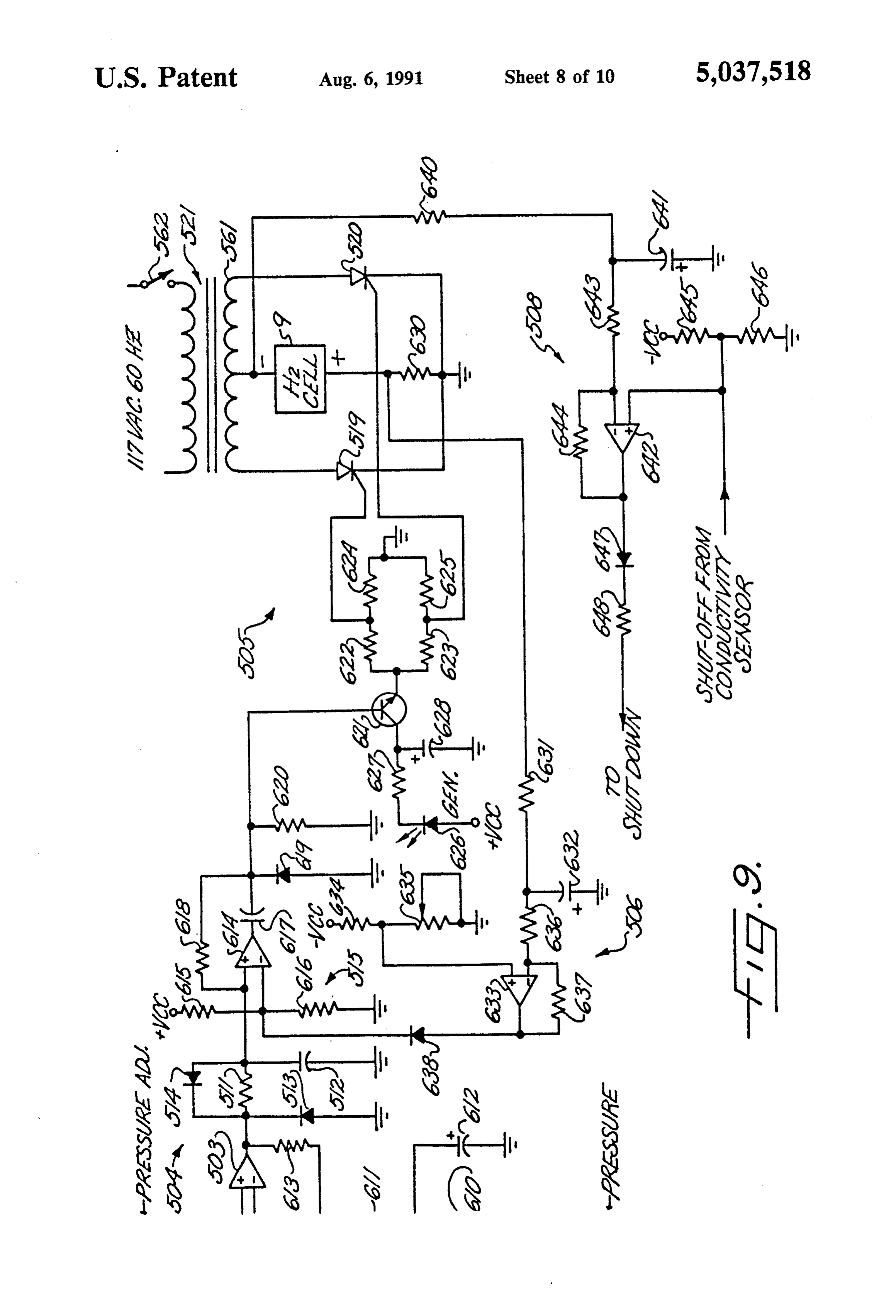
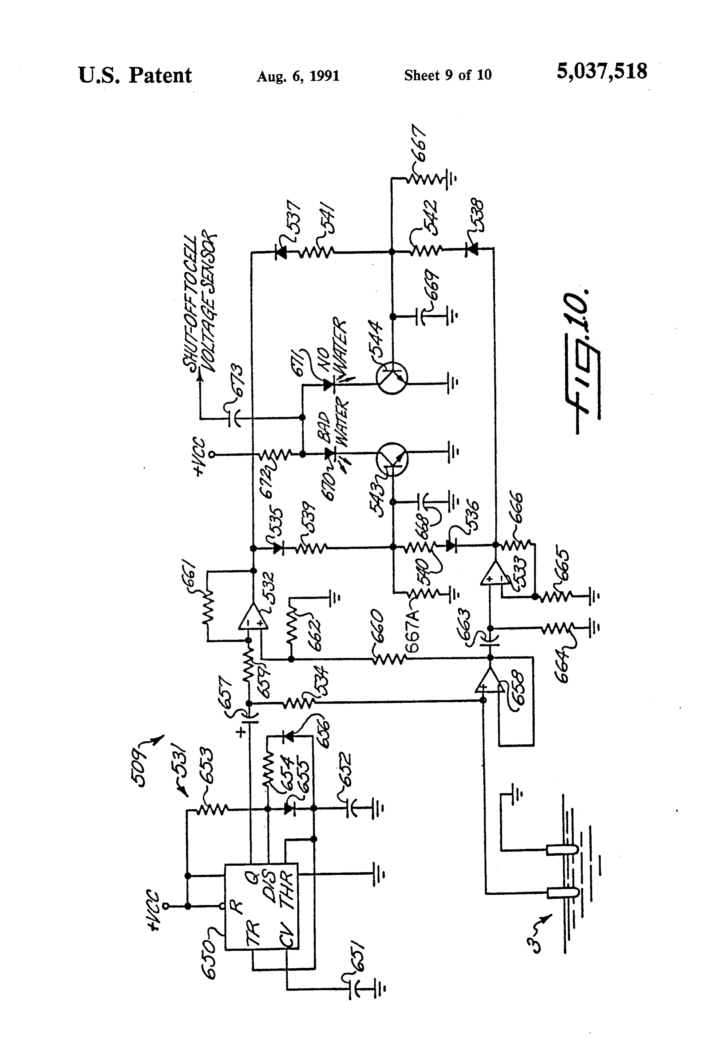
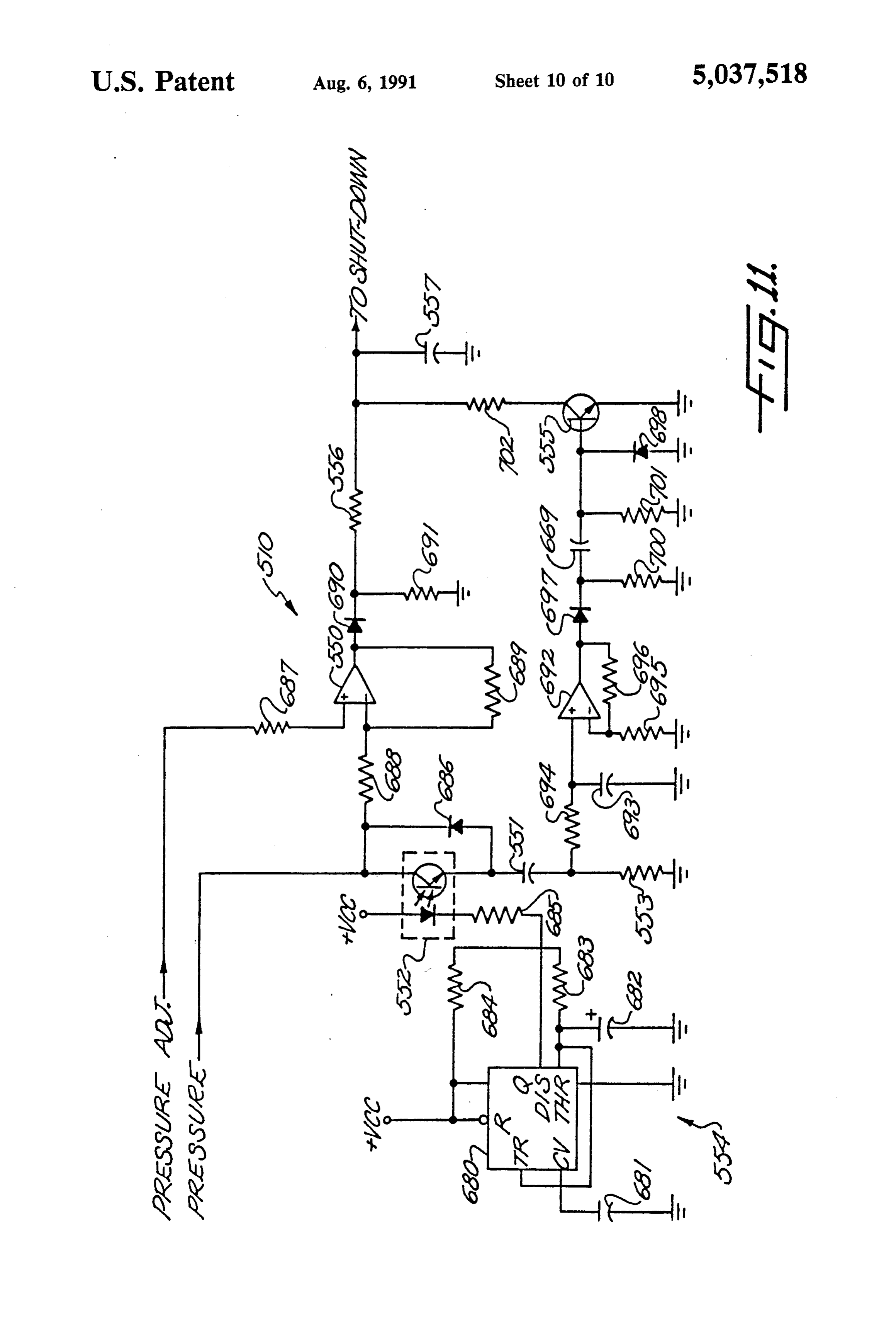
FIG. 1 is a schematic illustration of an electrolytic water, causes dissociation of the water contained within cell hydrogen generator embodying the present inven the solid-electrolyte membrane in the cell. This irre tion; 35 versibly "dries out' the membrane, thereby destroying FIG. 2 is an exploded perspective of the electrolytic the membrane and requiring replacement. Similarly, if cell in the hydrogen generator of FIG. 1; the electrolytic cell were allowed to run with an impure FIG. 3 is an exploded side elevation, partially in sec water supply, the membrane would soon become con tion, of the hydrogen-water separator in the generator taminated with impurities. Again this would destroy, of FIG. 1; and require replacement of, the membrane. FIG. 4 is a block diagram of electrical circuits in the As an additional protective measure the reservoirs 1 hydrogen generator; and 2 may be provided with a deionizing agent sealed in FIG. 5 is a simplified schematic diagram of electrical a porous envelope or bag 4 to alleviate the problem of circuits for controlling current supplied to the hydro possible membrane contamination from small quantities gen generator cell to obtain a selected level of hydrogen 45 of impurities, including metal ions generated in the pressure; closed-loop water system.
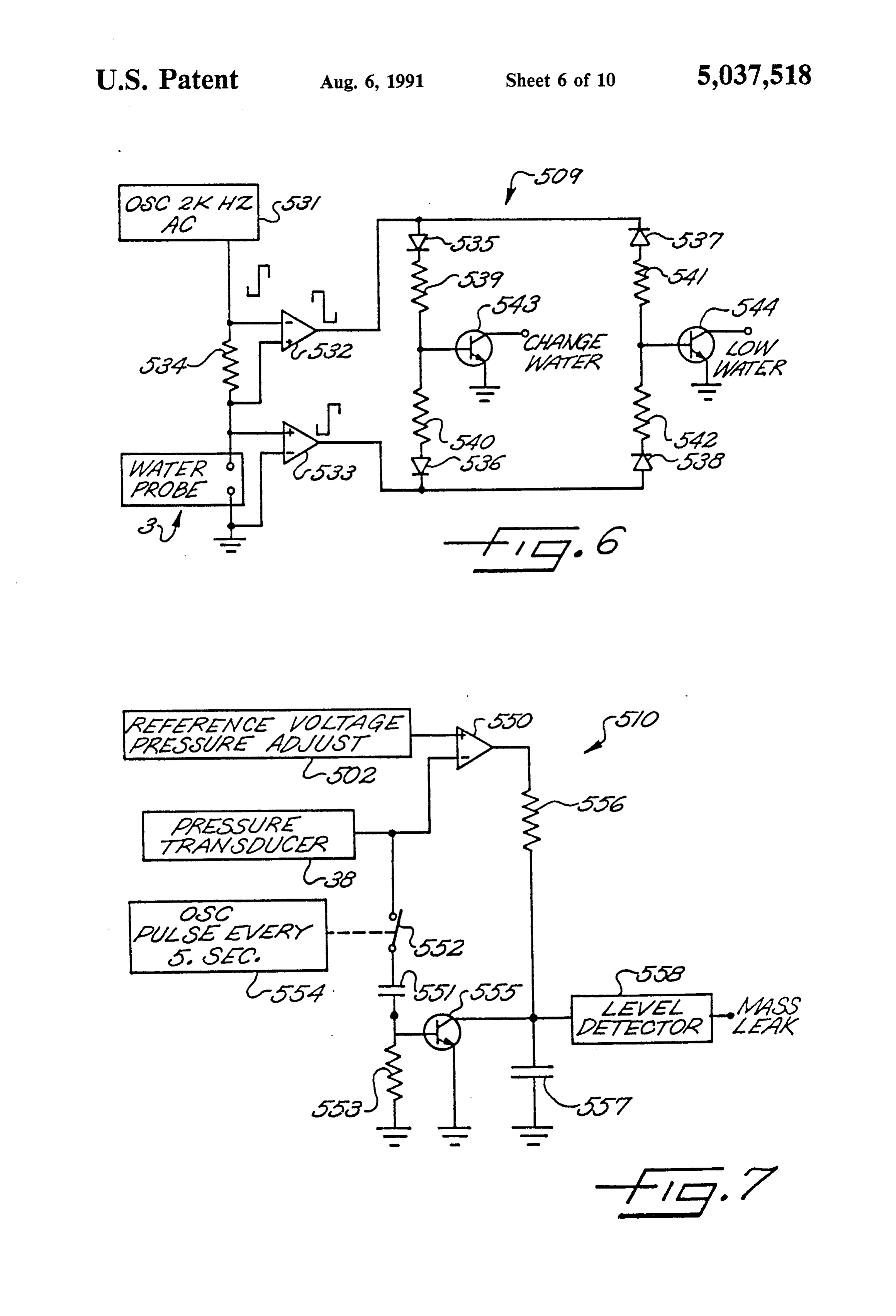
FIG. 6 is a simplified schematic diagram of electrical The reservoirs 1 and 2 are preferably positioned circuits which are used for detecting excessive water above the electrolytic cell C so that water flows into the conductivity and lack of water in the hydrogen genera cell by gravity. The water levels in the reservoirs re tor cell; 50 main virtually the same since they are connected in FIG. 7 is a simplified schematic diagram of electrical parallel to a common water supply line 5 to the cell. circuits which are used for detecting a failure of the Thus, the water flows from the reservoirs 1 and 2 hydrogen generator to achieve a selected pressure, for through respective lines 6 and 7 which converge at a Y example, due to a massive leak in the generator; connection 8 to the supply line 5. A check valve 9 is FIG. 8 is a detailed schematic diagram of circuits for 55 provided in the supply line 5 downstream of the con indicating a selected hydrogen pressure, Sensing the nection 8 to prevent the back flow of water into the actual hydrogen pressure, and shutting down the gener lines 6 and 7.
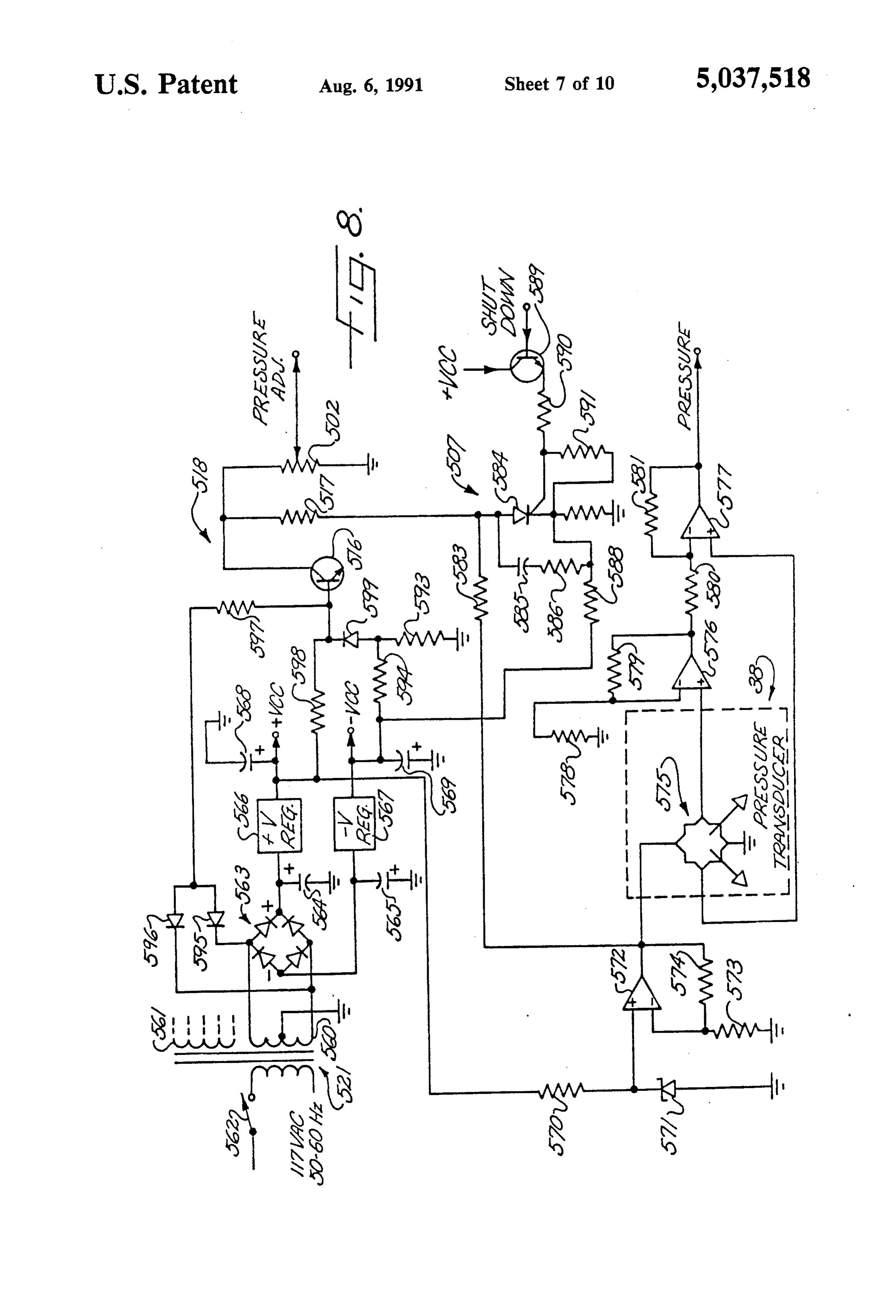
ator under certain abnormal conditions; A drain line 5a is connected to the water supply line FIG. 9 is a detailed schematic diagram of the circuits 5 viaT connection 5b. This drain line Sa can be used not for controlling the current supplied to the hydrogen 60 only to drain the system when desired, but also to con generator cell to obtain a selected level of hydrogen nect the system to an auxiliary or larger water supply pressure; reservoir for applications where it is desired to have the FIG. 10 is a detailed schematic diagram of the circuits unit operate continuously for periods longer than can be for detecting excessive water conductivity and lack of accommodated by the two reservoirs 1 and 2. water in the hydrogen generator; and 65 The water enters the water-tight housing of the elec FIG. 11 is a detailed schematic diagram of the circuits trolytic cell C through an inlet port 10. The inlet port 10 for detecting the failure of the hydrogen generator to leads to an internal conduit 11 which conducts the achieve a selected pressure. water to an anode chamber 12, located directly beneath
Page 14
an ion-exchange membrane 14 which serves as the solid detail in U.S. Pat. Nos. 3,735,558 and 4,705,543. Other. electrolyte for the cell. A cathode chamber 13 is formed drying devices, such as a water trap for example, could directly above the membrane 14, and an electrical be used in place of the drying tube. power supply (not shown in FIG. 1) is connected across From the drying coil 31, the hydrogen gas passes into the electrodes in the two chambers 12 and 13 so that the a desiccator chamber 33 filled with a desiccant such as water is dissociated into ionic hydrogen and oxygen via silica gel or a molecular sieve, either of which can be electrolysis. The positively charged hydrogen ions are regenerated from time to time rather than being re transported across the ion-exchange membrane 14 into placed. The partial drying of the hydrogen before it the cathode chamber 13 along with water molecules. reaches the desiccator chamber 33 extends the intervals The negatively charged oxygen ions recombine at the 10 at which the desiccant must be regenerated. The gas anode to form molecular oxygen within the anode flows downwardly through the desiccant and exits at chamber 12. the bottom of the chamber 33 through a tube 34. The oxygen-enriched water exits the anode chamber The release of hydrogen gas from the unit is con 12 through an internal conduit 15 leading to an outlet trolled by a shutoff valve 35 which connects the tube 34 port 16 which communicates with a return conduit 17 15 to a hydrogen output port 36. A pressure gauge 37 to return the oxygen-enriched water to the reservoir 2. monitors the hydrogen pressure in the conduit 34 and is The return conduit 17 includes an oxygen vent 18 mounted on the front panel of the generator to display which separates the oxygen gas from the water by vent the pressure reading to the user. A pressure transducer ing the oxygen to the atmosphere. The reservoir 2 pref 38 also monitors the hydrogen pressure in the tube 34 erably includes a similar vent in its cap 19 which vents 20 and produces a corresponding electrical signal which is any oxygen remaining in the water that is returned to used to control the electrical power supplied to the this reservoir. electrolytic cell, as will be described in more detail Within the cathode chamber 13, the positively below.
charged hydrogen ions combine to form, molecular A preferred embodiment of the electrolytic cell of the hydrogen. These hydrogen molecules, along with any 25 present invention is shown in FIG. 2. This cell has a water molecules transported across the membrane 14, watertight housing 100 which clamps a solid polymeric flow out of the cathode chamber 13 through a conduit ion-exchange membrane electrolyte 107 between a cata 20 into a hydrogen-water separator 21. The water re mains at the bottom of the separator 21 where a float lytic cathode 102 and a catalytic anode 103. These elec trodes 102 and 103 preferably have a thickness of at valve 22 opens to discharge water into a conduit 23 least about
0.020 inch each. Electrical power is supplied whenever the water rises above the desired level. This to the cathode insures that the upper region of the separator 21 remains and 102b at opposite 102 through two attachment points 102a open for the collection of hydrogen gas. Thus, hydro receives electrical power ends thereof, and the anode 103 gen diffuses from the water into the upper region of the ment points 103a and 103b. through The heat two similar attach generated by resis separator 21 for collection and further processing. 35 tance is directly related to the distance the current must
The water conduit 23 returns the water therein to the reservoir 1 via outlet port 24, return line 25 and a hydro travel through the resistor. The electrodes in electro gen vent 26 which separates entrained hydrogen gas lytic cells act as resistors, and thus, heat is generated as from the water by venting the hydrogen to the atmo a current is passed through them. The heat generated in sphere. The cap 27 of the reservoir 1 preferably in the electrodes of the present invention is substantially cludes a similar vent which removes any remaining reduced by providing two electrical inputs for each hydrogen from the water that is returned to this reser electrode. Gaskets 106, 109 and 110 are provided to insure a water-tight construction for the electrolytic voir. Pressure for returning water from the separator 21 cell.
to the reservoir 1 is provided by the accumulated hy anodeIn103 addition, a gasket 105 is provided between the drogen in the separator, which forces water through the insulate theand 45 the base of the housing 100 to electrically anode 103 from the base of the housing 100.
conduit 23 whenever the float valve 22 is open.
The hydrogen gas that accumulates in the separator This gasket 105 also has sufficient thermal conductivity 21 has a certain amount of water vapor entrained to ensure good heat transfer from the electrodes into the housing 100, which serves as a heat sink. The housing therein. This water vapor must be removed from the hydrogen because most uses for the hydrogen require 50 100 in turn is fastened to a metal chassis which also pure hydrogen. Part of the water is removed from the becomes part of the heat sink.
The two gaskets 106 and 109 are preferably laminates hydrogen gas by passing the gas through a coalescing filter 28 in the upper region of the separator 21. As is having a catalytic screen 101 disposed between two well known, a coalescing filter forms a tortuous path non-conductive annular gaskets. The screen is in electri which removes liquid droplets from a gas flowing there 55 cal contact with the adjacent electrode and functions as through. a part of that electrode. To ensure that the screens In accordance with a further feature of this invention, firmly engage the respective electrodes, as well as the the hydrogen is further dried by passing it through a solid-electrolyte membrane 107, a pressure disc 108, of drying tube made of a material which selectively ad the same diameter as the screens, is disposed between sorbs water vapor from gas flowing through the interior the cathode 102 and the uppermost gasket 110 so that of the tube, and transfers the adsorbed water to the when the two housing sections are drawn together, the exterior of the tube. Thus, from the separator 21, the disc 108 exerts pressure on the screens. Water enters the hydrogen passes upwardly through a conduit 30 to a cell housing 100 through a tee connection 111 con drying coil 31 which removes a substantial portion of nected to the housing by a stem 112, with the other end the water vapor from the hydrogen gas. The absorbed 65 of the tee leading to a drain port. Water and oxygen are water then passe through the walls of the tubing and is removed from the housing via an outlet 113, and water evaporated from the outside surface of the tubing. Ex and hydrogen are removed from the separator 21 via an amples of suitable drying coils are described in more outlet 114 in the housing 100.
Page 15
Although the invention has been illustrated with only Turning now to FIG. 4, there is shown a block dia one electrolytic cell, i.e., one pair of electrodes and one gram of the preferred electrical circuits in the hydrogen ion-exchange membrane, it will be understood that two generator. To provide a selected pressure of hydrogen or more cells may be stacked on top of each other in a gas, the pressure of the hydrogen gas is measured with single housing in order to increase the hydrogen-pro the pressure transducer 38, and the hydrogen generator ducing capacity of the unit. cell C is supplied with an amount of electrical current FIG. 3 illustrates a preferred embodiment of the hy that is regulated in response to the difference between drogen-water separator 21. The separator is constructed the measured pressure and the desired pressure. The as an elongated, cylindrical vessel attached to the elec desired pressure is indicated by the reference voltage trolytic cell housing and communicating with the cath O from the pressure adjust potentiometer 502, and a differ ode chamber of the electrolytic cell through the inlet ential amplifier 503 compares the reference voltage to a port 20. Hydrogen-enriched water enters the separator pressure-indicating voltage from the pressure trans through the inlet port 20, and the water level gradually ducer 38 to provide a control signal for regulating the rises around a hollow stem 201 fitted into the top of the electrical current to the cell.
housing 100. The float valve 22 cooperates with the 15 Instead of using the output pressure as the controlling stem 201 and is constructed from a tube 202 attached to parameter, the hydrogen flow rate in the hydrogen a base 203 which in turn is attached to a hollow float output line could be used as the controlling parameter. valve body 204 sealed by a top 205. The tube 202 tele This would be desirable for certain applications where a scopes over the stem 201 having a central bore 206 controlled flow rate is more important than a controlled extending along its axis. The tube 202 has two slots at its 20 pressure. In this case, the pressure transducer 38 would upper end to facilitate the flow of water between the be replaced with a flow rate sensor, such as by sensing main vessel of the separator 21 and the stem 201. differential pressures in the hydrogen output line. As the level of hydrogen-enriched water rises in the The preferred method of regulating the current to the separator, the float assembly valve 22 lifts off the stem cell is pulse width modulation of signals gating a pair of 201, thereby opening the top of the stem 201. Hydro 25 silicon controlled rectifiers. Therefore, a pulse width gen-enriched water flows through the stem to a conduit modulator 504 is responsive to the control signal from within the top of the housing 100 and then on to the the differential amplifier 503 and provides variable main reservoir 1, thereby lowering the water level in width gate pulses to the SCR circuits 505. To limit the the separator 21. When the water level in the separator cell current to a safe value, the cell current is sensed by is sufficiently low, the float valve 22 seats on top of the 30 a threshold comparator 506 which provides a signal to stem 201, thereby closing the water return line to the inhibit the pulse width modulator 504 when a predeter reservoir 1. mined maximum cell current is reached. If the float valve 22 should ever become inoperable, a To ensure that the hydrogen generator operates ball valve 207 at the top of the separator chamber en within guaranteed specifications, the current to the sures that water never exits the separator 21 into the 35 hydrogen-generating cell C is shut off entirely when hydrogen conduit 30. If the water level should ever rise certain conditions occur. The sensing of these condi to the position of the ball valve 207, a ball 208 rises into tions triggers a one-shot 507 that is reset only upon a socket 209, sealing the outlet tube 30. The ball valve cycling a power switch “off” and then "on'. In the 207 protects the rest of the unit from contamination by usual case appropriate maintenance or servicing would liquid water, and also protects any sensitive equipment be performed when the power switch is off before it is the operator may have connected to the hydrogen out turned back on. For convenience of circuit design the let port. one-shot shuts off the current to the hydrogen cell by The hydrogen-water separator also includes a pres driving the reference voltage from the potentiometer sure relief valve 210 connected to a port 211 in the side 502 to an extreme minimum value. Alternatively, the wall of the main vessel of the separator 21. In the event 45 one-shot 507 could directly inhibit the SCR circuits 505. that the pressure in the hydrogen collection becomes Normally the voltage across the anode and cathode in too great, the relief valve 210 will open, relieving the the hydrogen generator cell C will not exceed a known pressure. Accordingly, this valve prevents any acciden maximum voltage. To shut off the hydrogen generator tal increase in pressure in the separator over acceptable when the cell voltage exceeds the maximum voltage, a limits which could damage the unit, any equipment 50 cell voltage threshold detector 508 supplies a shut connected to the unit, or the operator. The relief valve down signal to the one-shot 507.
210 is particularly important in view of the fact that the To generate hydrogen gas and to avoid permanent ball valve 207 can close the only other gas exit from the damage to the solid electrolyte in the hydrogen genera separator 21. tor cell C, the solid electrolyte should always be im As discussed above, the ion-exchange membrane 55 mersed in water. Also, to guarantee that pure hydrogen utilized in electrolytic cell gas generators is very deli is generated and to avoid contamination of the solid cate. For example, a sudden release of pressure in the electrolyte, the water must be deionized and should separator can delaminate the membrane and render it have a resistivity of at least a certain minimum value inoperable. The float ball valve 207 included in the such as 100,000 ohm/cm. These conditions are insured hydrogen gas collection chamber will prevent such a 60 by a water quality and level detector 509 that provides sudden loss of gas pressure in the unit. For example, if a shut-down signal to the one-shot 507 in the absence of the outlet valve 35 were to be open to the outside atmo a minimum level of high quality water in the hydrogen sphere without resistance, hydrogen would rush out, generator cell C.
rapidly reducing the pressure in the system. However, When the hydrogen generator is unable to provide in the event of such an occurrence, the rapid flow of 65 hydrogen gas at the desired pressure, a hydrogen leak hydrogen past the ball 208 will lift the ball into the might be the cause. Therefore, a mass leak detector 510 socket 209, sealing the outlet tube 30. This will prevent provides a shutdown signal to the one-shot 507 when any damage to the ion-exchange membrane. the hydrogen pressure fails to increase at a predeter
Page 16
mined minimum rate if it has not already reached the 538; resistors 539, 540, 541, and 542; and transistors 543. desired pressure. and 544. When both of the amplifiers 532 and 533 gener Turning now to FIG. 5, there is shown a simplified ate substantial signals, then the diode bridge is balanced diagram of the pulse width modulator 504 and the SCR and neither of the transistors 543 and 544 is activated. drive and power control circuits 505. The pulse width 5 When the water has a resistivity that is too low, the modulator 504 includes a resistor 511, a capacitor 512, signal from the first differential amplifier 532 cause the directional diodes 513 and 514, and a level detector 515. diode 535 and the transistor 543 to conduct, thereby Associated with the pulse width modulator 504 is a signaling that the water should be changed. When transistor 516 and a resistor 517 which are responsive to water is absent from between the electrodes of the a source 518 of pulses at the zero crossings in the 60-Hz. 10 water probe 3, then the signal from the second differen or 50-Hz. voltage from the power lines. The transistor tial amplifier 533 causes the diode 538 and the transistor 516 applies the pulses to the reference voltage from the 544 to conduct, thereby signalling that the water level is potentiometer 502 and the pulses are transferred low.It will be understood that sensors other than elec through the differential amplifier 503 and cause the output of the differential amplifier to go negative and be 15 trodes may be used to sense the "charge water' or "low clamped by diode 513 so that the capacitor 512 is dis water' conditions. For example, an optical sensor or a charged to approximately ground potential through the float switch could be used to sense the water level. diode 514 during each zero crossing. The pulses are Turning now to FIG. 7, there is shown a simplified relatively narrow and therefore during the absence of schematic diagram of the massive leak detector 510. the pulses the capacitor 512 is charged through resistor 20 The massive leak detector is operative only when the 511 up to a value responsive to the difference or be hydrogen pressure has failed to reach the desired pres tween the desired pressure and the measured pressure. sure. This condition is detected by a comparator 550 To provide pulses at a 120-Hz. or 100-Hz. rate and at that compares the reference voltage from the pressure phase angles proportional to the pressure difference, the adjusting potentiometer 502 to the pressure indicating voltage across the capacitor 512 is applied to a level 25 signal from the pressure transducer 38. The differential detector 515 which has a predetermined threshold amplifier 550 is matched with the differential amplifier above ground potential. Pulses from the level detector 503 of FIG. 5 so that the output signal of the amplifier 515 are applied to the gates of the SCRs 519 and 520 550 will be at a positive voltage only when the hydro which are wired to the hydrogen generating cell C and gen generating cell is energized and the measured pres a center-tapped secondary of a power transformer 521 30 sure has failed to reach the desired pressure. Under in a full-wave rectifier circuit. Since the gating pulses to these conditions, the hydrogen generating cell should the SCRs occur at a variable time delay from the zero generate a sufficient amount of hydrogen gas to increase crossings in the power line voltage, the conduction the pressure at a substantial rate until the measured angle of the SCRs and the current through the cell are pressure reaches the desired pressure. adjusted in response to the difference between the de 35 To determine whether the measured pressure is sub sired pressure and the measured pressure. stantially increasing, the massive leak detector 510 in Turning now to FIG. 6, there is shown a simplified cludes a capacitor 551 which is periodically connected schematic diagram of the water quality and level detec by a controlled switch 552 to the output voltage of the tor circuits 509 which interrupt the supply of electrical pressure transducer 38. The switch 552 is pulsed closed power to the electrolytic cell whenever (1) the water 40 at the prescribed intervals. The increase in the pressure level in the reservoir becomes too low, or (2) impure indicating voltage over the prescribed interval appears water is present in the reservoir, e.g., as a result of the as a voltage pulse across a resistor 553 in series with the addition of tap water rather the deionized distilled wa capacitor 551. If the hydrogen generator is operating ter. These circuits include the water probe 3 having a properly, then the voltage pulse turns on a transistor pair of spaced electrodes disposed in the water reservoir 45 555.A massive leak is detected when the transistor 555 1, an oscillator 531 for energizing the electrodes, a first differential amplifier 532 and a second differential am fails to be turned on within a prescribed time interval plifier 533. The first differential amplifier 532 senses the whenever the measured pressure is below the desired voltage across a resistor 534 which is in series with the pressure. For this purpose the output of the comparator water probe 3. The second differential amplifier 533 50 550 charges a capacitor 557 through a resistor 556, and senses the voltage across the water probe 3. The value the capacitor 557 is connected to the collector of the of the resistor 534 and the respective gains of the differ transistor 555 to discharge the capacitor when the tran ential amplifiers 532 and 533 are selected so that both of sistor turns on. The voltage across the capacitor 557 is the differential amplifiers provide respective alternat fed to a shutdown detector that has a predetermined ing-current output signals that are substantial only 55 threshold voltage to which the capacitor 557 is charged when the resistance between the electrodes of the water by the comparator 550 unless the transistor 555 turns probe falls within a predetermined range. If the level of O.
the water in the water reservoir 1 falls below the tips of When a massive leak is present, the measured pres the electrodes in the water probe 3, then an insubstantial 60 sure will fail to reach the desired pressure and hence the amount of current will flow through the resistor 534. In capacitor 557 will be charged. Also, the measured pres this case only the second differential amplifier 533 will sure will fail to increase at a rate sufficient to turn the generate a substantial output signal. Conversely, when transistor 555 on to discharge the capacitor 557. There the resistivity of the water falls below the minimum fore, the shutdown detector 558 will assert a signal resistivity, then only the first differential amplifier 532 indicating the presence of the massive leak and fire the will generate a substantial output signal. 65 one shot 507 (FIG. 4) permanently. To indicate the error conditions, the outputs of the Turning now to FIG. 8, there is shown a detailed two differential amplifiers 532,533 are wired in a bridge schematic diagram of the preferred circuits associated circuit including directional diodes 535, 536, 537, and with the pressure-adjusting potentiometer 502, the one
Page 17
shot 507 and the pressure transducer 38. The electronic circuits 506, and the cell over voltage detector 508. The circuits are powered by a secondary 560 of the power pressure-indicating signal from the pressure transducer transformer 521 that is separate from the secondary 561 (38 in FIG. 8) is applied to the differential amplifier 503 that supplies current to the hydrogen-generating cell C. through a low-pass filter including series resistors 610 The primary of the power transformer 521 is connected and 611, and a shunt capacitor 612. The gain of the to the power lines through a switch 562. differential amplifier 503 is set by a feedback resistor To provide positive (--VCC) and negative (-VCC) 613. The level detector 515 includes a differential ampli Supply voltages for the electronic circuits, the second fier 614 having a threshold set by a voltage divider ary coil 560 has a grounded center tap and is connected including resistors 615 and 616. To generate a positive to a bridge rectifier 563. The positive and negative 10 pulse when the threshold is exceeded, the output of the outputs of the bridge rectifier 563 are shunted to ground differential amplifier 614 is connected to a capacitor 617 through respective electrolytic filter capacitors 564 and which in turn is connected to a positive feedback resis 565. In addition, the positive and negative output volt tor 618. The capacitor 617 is also shunted to ground by ages of the bridge rectifier 563 are regulated by respec a clamping diode 619 and a resistor 620 so that positive tive positive and negative voltage regulators 566 and 15 pulses are generated across the resistor 620. 567. The outputs --VCC and - VCC are shunted to To drive the gates of the SCRs 519 and 520, the ground by respective electrolytic capacitors 568 and pulses across the resistor 620 are applied to the base of 569. a transistor 621 wired in an emitter-follower configura To provide a voltage reference for the pressure trans tion. The emitter of the transistor 621 is connected to ducer 38, the output of the positive voltage regulator respective series resistors 622, 623 and shunt resistors 566 is connected through a voltage-dropping resistor 624 and 625 which are in turn connected to the gates of 570 to a zener diode 571. The voltage across the zener the SCRS.
diode 571 is buffered by an amplifier 572 having its gain In order to indicate that the SCRs are being turned set by resistors 573 and 574. on, the collector of the transistor 621 is fed by current To measure the hydrogen gas pressure, the pressure 25 through a light-emitting diode 626 having its anode transducer 38 has a balanced resistive strain gage bridge connected to +VCC. A capacitor 628 supplies current 575, and the difference voltage across the bridge is for pulses to the SCR gates, and the capacitor 628 and amplified by a pair of differential amplifiers 576 and 577 a resistor 627 average these high current pulses to ap that are wired so as not to amplify common mode sig proximately d-c. for the light-emitting diode 626. nals. The amplifiers work in connection with feedback 30 To limit the current through the silicon controlled resistors 578,579,580, and 581. rectifiers to a safe maximum value, the current is sensed The pressure-adjusting potentiometer 502 is con by a series resistor 630 having a relatively low resis nected through resistors 517 and 583 to the reference tance. The current through this resistance creates a voltage from the amplifier 572. The voltage reference, relatively small negative voltage which is low-pass however, is removed from the pressure-adjusting poten 35 filtered by a resistor 631 and an electrolytic capacitor tiometer 502 when the one-shot 507 is triggered by a 632.
shut-down signal. The bistable element of the one-shot The maximum cell current detector 506 further in is an SCR 584 having a snubbing capacitor 585 and cludes a differential amplifier 633 which compares the resistor 586. The cathode of the SCR is biased by resis voltage across the capacitor 632 to a reference voltage tors 587 and 588 to a negative voltage between ground provided by a voltage divider including a resistor 634 and - VCC. To trigger the SCR, a transistor 589 re and a variable resistor 635. The gain of the amplifier 633 ceives the shut-down signal and is wired as an emitter is set by a series resistor 636 and a negative feedback follower to drive the gate of the SCR through a cur resistor 637. The output of the amplifier 633 is fed back rent-limiting resistor 590 and a shunt resistor 591. to the threshold-detecting amplifier 614 through a di The voltage across the pressure-adjusting potentiom 45 rectional diode 638. When the current through the hy eter 502 is also interrupted periodically by pulses at the drogen-generating cell C is less than a predetermined zero crossings in the power line voltage. The pulse maximum value set by the variable resistors 635, then generator circuits 518 include a transistor 516 having its the diode 638 will be reverse biased, and the amplifier emitter held at a negative voltage by a resistor 593 633 will have a negligible effect on the threshold-detect connected to ground and a resistor 594 connected to SO ing amplifier 614. However, when the current through - VCC. To turn the transistor 516 on and off at the zero the hydrogen-generating cell C exceeds the predeter crossings of the power line voltage, the transistor is mined maximum limit, then the diode 638 is forward normally turned off by a negative voltage from either biased and the amplifier 633 will inhibit the threshold one of two directional diodes 595 and 596 connected to detecting amplifier 614. Therefore, when the maximum the AC inputs of the bridge rectifier 563. The base of 55 current limit is exceeded, gate pulses will be applied at the transistor 516 is connected to these diodes 595 and maximum phase to hold preset maximum current levels 596 through a resistor 597, and is also connected to the through the hydrogen-generating cell C. positive supply --VCC through a resistor 598, and the The over voltage detector 508 shuts off the hydro values of the resistors 597 and 598 are selected so that gen-generating cell entirely when the cell voltage ex the transistor 516 is turned on for a short time during ceeds a certain maximum limit. The cell voltage is low each zero crossing. The base and the emitter of the pass filtered by a resistor 640 and an electrolytic capaci transistor 516 are shunted by a directional diode 599 to tor 641. The cell over voltage detector 508 further prevent the base of the transistor from being reversed includes a differential amplifier 642 having again set by biased. a series resistor 643 and a negative feedback resistor Turning now to FIG. 9 there is shown a detailed 65 644. The desired voltage threshold is provided by a schematic diagram of the differential amplifier 503, the resistor voltage divider including resistors 645 and 646. pulse width modulator 504, the SCR drive and power The amplifier 642 is connected to the transistor 589 of control circuits 505, the maximum cell current feedback the one-shot circuit 507 of FIG. 8, through a directional
Page 18
diode 647 and a resistor 648. Therefore, when the cell rent sensing resistor 553 but this voltage pulse is ampli voltage exceeds the threshold value, the amplifier 642 fied by the amplifier 692 to have a sufficient amplitude forward biases the diode 647, and current flows through to turn on the transistor 555. The transistor 555 will the diode to turn on the transistor 589 in FIG. 8 to therefore discharge the capacitor 557. The collector of trigger the one-shot (507 in FIG. 8) and shut off the the transistor 555 is connected to the capacitor 557 current to the hydrogen-generating cell C. through a current limiting resistor 702. If, however, the Turning now to FIG. 10, there is shown a detailed pressure is not substantially increasing and the amplifier schematic diagram of the water quality and level detec 550 has a positive output voltage indicating that the tor 509. The oscillator 531 includes an integrated circuit desired pressure has not been reached, then the capaci 650 that works in connection with capacitors 651, 652, 10 tor 557 will charge up to the threshold of the one-shot resistors 653, 654 and directional diodes 655 and 656. (507 of FIG. 8) to shut down the hydrogen-generating The signal from the integrated circuit 650 is coupled cell (C in FIG. 9).
through a tantalum capacitor 657 to the current-sensing As one feature of the present invention, water is recy resistor 534. Due to the rather high resistance being cled from the hydrogen-water separator to the anode sensed, the signal across the water probe 3 is buffered 15 side of the electrolytic cell by returning water from the by a follower amplifier 658 before being applied to the separator to the water reservoir. This feature permits amplifiers 532 and 533. The first amplifier 532 works in water to be supplied continuously from the reservoir to connection with resistors 659, 660, 661 and 662, and the the anode chamber, without the need to periodically second amplifier 533 works in connection with a cou reverse the movement of water molecules through the pling capacitor 663 and resistors 664, 665, and 666. 20 solid electrolyte and the attendant danger of drying out The outputs of the amplifiers 532, 533 are connected and irreversibly damaging the electrolyte. to the diode bridge including the diodes 535 to 538 and We claim:
the resistors 539 to 542. The midpoints of the diode 1. Apparatus for generating hydrogen by the electro bridqe are connected to the transistors 543 and 544. To lytic dissociation of water, said apparatus comprising: reject noise, the midpoints of the bridge are shunted to 25 an electrolytic cell having a cathode and an anode ground by resistors 667, 667a and capacitors 668 and separated by a solid-electrolyte whereby the cath 669. ode is on one side of the solid electrolyte and the To indicate the “charge water" or "no water' error anode is on the other side of the solid electrolyte, conditions, the collectors of the transistors 543 and 544 an electrical power supply connected to said electro are connected to respective light-emitting diodes 670 30 lytic cell for applying a voltage across said cathode and 671 which share a common current-limiting resistor and anode, 672. To shut off the current to the hydrogen-generating a water reservoir connected to said electrolytic cell cell (C in FIG. 9) when either the "change water' or for supplying water to said electrolytic cell on the "no water' error is detected, the voltage across the same side of the solid electrolyte on which said current-limiting resistor 672 is coupled through a capac 35 anode is located, itor 673 to the voltage reference in the cell over voltage a hydrogen-water separator connected to said elec detector 508 of FIG. 9. This is the most convenient method of connecting the water quality detector to the trolytic cell for receiving hydrogen and water from one-shot 507 of FIG. 8. said electrolytic cell on the same side of the solid Turning now to FIG. 11 there is shown a detailed electrolyte on which said cathode is located, and schematic diagram of the massive leak detector 510. separating the hydrogen from the water, The pulse generator 554 includes an integrated circuit a pressure relief valve included in said hydrogen 680 working in connection with capacitors 681, 682 and water separator for discharging hydrogen from resistors 683 and 684. The controlled switch 552 is pref. said separator to the atmosphere in response to an erably an optical coupler. The light-emitting diode of 45 increase in the pressure of said hydrogen in said the optical coupler 552 is connected to the output of the separator beyond a predetermined level, and integrated circuit 680 through a current-limiting resistor a water return line connecting said hydrogen-water 685. Preferably a directional diode 686 shunts the con separator to said water reservoir for returning trolled switch 552 to ensure that the phototransistor of water from said hydrogen-water separator to said the switch is not reverse biased. 50 water reservoir whereby said water is recycled to The differential amplifier 550 works in connection the anode side of said electrolytic cell. with resistors 687, 688 and 689. The amplifier 550 2. The apparatus of claim 1 which includes control charges the capacitor 557 through a directional diode means in said hydrogen-water separator for opening 690 and the resistor 556. When the output voltage of the and closing said water return line in accordance with amplifier 550 is negative, the capacitor 557 discharges 55 the water level in said separator.
through the resistor 556 and a shunt resistor 691. 3. The apparatus of claim 1 which includes a hydro The capacitor 551 should have low leakage and is gen outlet in said separator, and a float valve in said hydrogen-water separator for closing said hydrogen preferably a polycarbonate capacitor.
As shown in FIG. 11, it is preferable to provide an outlet in response to an increase in the water level in amplifier 692 between the resistor 553 and the transistor 60 tosaid separator to the level of said hydrogen outlet, so as 555. The amplifier 692 works in connection with a ca theprevent event water from entering said hydrogen outlet in of a malfunction of said control means.
pacitor 693 and resistors 694,695 and 696. The output of the amplifier 692 is coupled to the transistor 555 4. The apparatus of claim 1 which includes a hydro through a network including directional diodes 697 and gen outlet in said separator, and valve means associated 698, a capacitor 699 and resistors 700 and 701. 65 with said hydrogen outlet for closing said outlet in When the measured pressure has been substantially response to an increase in the rate of low of hydrogen increasing and the electronic switch 552 closes, a rela through said hydrogen outlet beyond a predetermined tively small voltage pulse is generated across the cur level.
Page 19
5. Apparatus for generating hydrogen by the electro sensing means in said hydrogen output line for pro lytic dissociation of water, said apparatus comprising: ducing an electrical signal representing the pres an electrolytic cell having a cathode and an anode sure of said hydrogen in said hydrogen output line, separated by a solid-electrolyte whereby the cath 5 a reference signal source for generating an electrical ode is on one side of the solid electrolyte and the signal representing a desired gas pressure in said anode is on the other side of the solid electrolyte, hydrogen output line, and control means response to the electrical signals from an electrical power supply connected to said electro said sensing means and said reference signal source lytic cell for applying a voltage across said cathode for interrupting the supply of electrical power to and anode and thereby supplying electrical power O said electrolytic cell when (1) said pressure of said to said cell, hydrogen in said hydrogen output line is less than a water reservoir connected to said electrolytic cell said desired gas pressure and (2) said actual gas for supplying water to said electrolytic cell on the pressure is increasing at a rate less than a predeter same side of the solid electrolyte on which said mined minimum rate.
anode is located, 15 7. Apparatus for generating hydrogen by the electro a hydrogen-water separator connected to said elec lytic dissociation of water, said apparatus comprising: trolytic cell for receiving hydrogen and water from an electrolytic cell having a cathode and an anode said electrolytic cell on the same side of the solid separated by a solid-electrolyte whereby the cath ode is on one side of the solid electrolyte and the electrolyte on which said cathode is located, and 20 anode is on the other side of the solid electrolyte separating the hydrogen from the water, said solid electrolyte comprising a solid polymer sensing means in said water reservoir for producing ion exchange membrane which is subject to delami an electrical signal in response to a predetermined nation in the event of a sudden reduction in pres change in the electrical conductivity of the water Sure, in said reservoir, and 25 an electrical power supply connected to said electro electrical control means responsive to the electrical lytic cell for applying a voltage across said cathode signal from said sensing means for automatically and anode, interrupting the supply of electrical power to said a water reservoir connected to said electrolytic cell electrolytic cell. for supplying water to the same side of the solid 6. Apparatus for generating hydrogen by the electro 30 electrolyte on which said anode is located, lytic dissociation of water, said apparatus comprising: a hydrogen-water separator connected to said elec trolytic cell for receiving hydrogen and water from an electrolytic cell having a cathode and an anode said electrolytic cell on the same side of the solid separated by a solid-electrolyte whereby the cath electrolyte on which said cathode is located, and ode is on one side of the solid electrolyte and the 35 separating the hydrogen from the water, said sepa anode is on the other side of the solid electrolyte, rator including a hydrogen outlet, an electrical power supply connected to said electro a hydrogen output line for receiving the hydrogen lytic cell for applying a voltage across said cathode from said hydrogen outlet in said separator, and and anode and thereby supplying electrical power excess flow valve means associated with said hydro to said cell, gen outlet in said separator for preventing delami a water reservoir connected to said electrolytic cell nation of said ion exchange membrane by closing for supplying water to said electrolytic cell on the said outlet in response to an increase in the hydro same side of the solid electrolyte on which said gen flow rate beyond a predetermined level. anode is located, 8. The apparatus of claim 7 wherein said valve means a hydrogen-water separator connected to said elec 45 comprises a ball valve connected to said hydrogen out trolytic cell for receiving hydrogen and water from flow rate of the ahydrogen let and containing ball which rises in proportion to the gas passing through said said electrolytic cell on the same side of the solid outlet, and a seal for receiving the ball and blocking said electrolyte on which said cathode is located, and hydrogen outlet when the ball rises to a predetermined separating the hydrogen from the water, 50 elevation corresponding to a predetermined hydrogen a hydrogen output line for removing the hydrogen flow rate.
from said separator, s: k
Provenance
- Collection
- Cited prior art
- Original PDF
- patentimages.storage.googleapis.com →
- Filed
- 1989-09-08
- Pages
- 19
- Method
- pdftotext (the PDF's own text layer) + pdftoppm 300dpi page scans
- Source
- Google Patents bibliographic record
- Granted
- 1991-08-06
- Inventors
- Stuart A. Young; Ronald A. Zweifel; Daniel L. Caldwell; Packard Instrument Co Inc
- Transcribed from
- patentimages.storage.googleapis.com →