patent · US4964524
Pressure vessel for hydrogen storage
23 October 1990
Page 1 — bibliographic record
United States Patent (19) 11 Patent Number: 4,964,524 Halene 45 Date of Patent: Oct. 23, 1990 (54 PRESSURE WESSEL FOR HYDROGEN 4,524,883 6/1985 Herring ............................... 220/465 STORAGE FOREIGN PATENT DOCUMENTS 75 Inventor: Clemens Halene, Duesseldorf, Fed. 701407 1/1965 Canada .................................... 220/3 Rep. of Germany 38-16675 of 1963 Japan .................. ... 220/3 73) Assignee: Gesellschaft fuer Hybrid und 13331 of 1896 United Kingdom .................... 220/3 Wasserstofftechnik mbH, Primary Examiner-George E. Lowrance
Muelheim/Ruhr, Fed. Rep. of Attorney, Agent, or Firm-Ralf H. Siegemund
Germany
(21) Appl. No.: 279,540 A pressure vessel for the storage of hydrogen in form of (22 Filed: Dec. 5, 1988 metal hydride is constructed to have an inner tube being (30) Foreign Application Priority Data relatively thin and made of material copper or alumi Dec. 4, 1987 DE Fed. Rep. of Germany ....... 374.1625 num having high thermal conductivity, but the strength of the inner vessel tube is insufficient by and in itself to 51) Int. Cl............................................... B65D 90/02 take up operating pressure in the interior when hydro 52 U.S. C. ......................................... 220/3; 206/07; gen is either fed into the interior of the tube or devel 220/414; 220/465 oped therein; an outer cylindrical tubular vessel jacket 58 Field of Search ........................... 220/3, 414, 465; is made of stainless steel and abuts against radially out 206/0.7 wardly extending ribs of the inner vessel establishing (56) References Cited flow channels the rib means are dimensioned not to
storage facility; axial end cap means closes the vessels 1,574,690 2/1926 Radabaugh ......................... 220/.465 on both ends; sealed gas nipples means in one or both 2,243,240 5/1941 Zerbe........... ... 220/3 caps feeds gas into and/or out of the interior of the inner 3,057,509 10/1962 Bernd ...... ... 220/3 vessel tube.
3,066,822 12/1962 Watter ..... ... 220/3 3,446,385 5/1969 Ponemon ... 220/3 4,446,111 5/1984 Halene ................................. 206/0.7 11 Claims, 3 Drawing Sheets
Page 2
Drawing sheet — no readable text.
Page 3
Drawing sheet — no readable text.
Page 4
Drawing sheet — no readable text.
Page 5
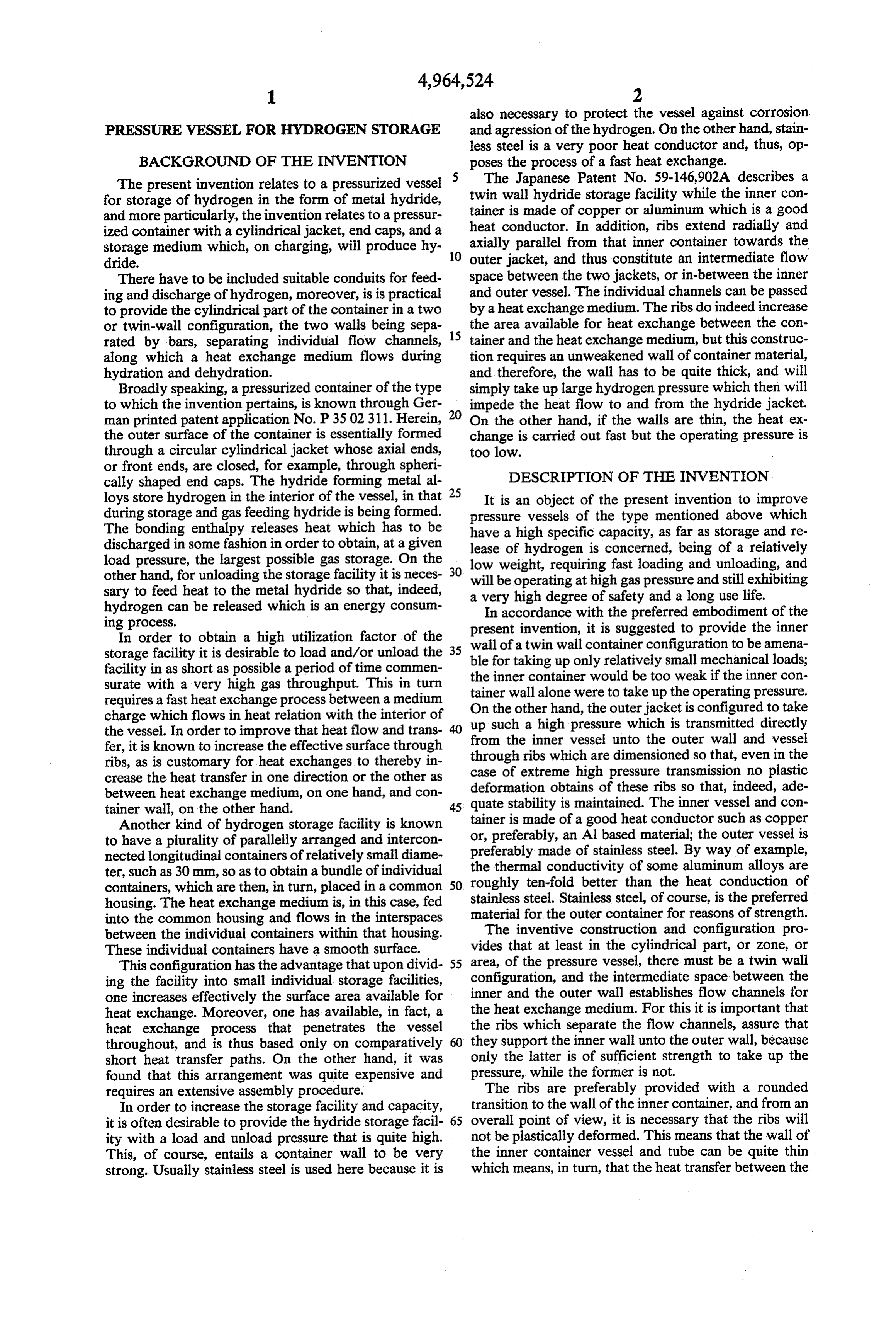
also necessary to protect the vessel against corrosion
PRESSURE WESSEL FOR HYDROGEN STORAGE and agression of the hydrogen. On the other hand, stain less steel is a very poor heat conductor and, thus, op
BACKGROUND OF THE INVENTION poses the process of a fast heat exchange. The present invention relates to a pressurized vessel 5 The Japanese Patent No. 59-146,902A describes a for storage of hydrogen in the form of metal hydride, twin wall hydride storage facility while the inner con and more particularly, the invention relates to a pressur tainer is made of copper or aluminum which is a good ized container with a cylindrical jacket, end caps, and a heat conductor. In addition, ribs extend radially and storage medium which, on charging, will produce hy 10 axially parallel from that inner container towards the dride. outer jacket, and thus constitute an intermediate flow There have to be included suitable conduits for feed space between the two jackets, or in-between the inner ing and discharge of hydrogen, moreover, is is practical and outer vessel. The individual channels can be passed to provide the cylindrical part of the container in a two by a heat exchange medium. The ribs do indeed increase or twin-wall configuration, the two walls being sepa 15 the area available for heat exchange between the con rated by bars, separating individual flow channels, tainer and the heat exchange medium, but this construc along which a heat exchange medium flows during tion requires an unweakened wall of container material, hydration and dehydration. and therefore, the wall has to be quite thick, and will Broadly speaking, a pressurized container of the type simply take up large hydrogen pressure which then will to which the invention pertains, is known through Ger impede the heat flow to and from the hydride jacket. man printed patent application No. P35 02311. Herein, 20 On the other hand, if the walls are thin, the heat ex the outer surface of the container is essentially formed change is carried out fast but the operating pressure is through a circular cylindrical jacket whose axial ends, too low.
or front ends, are closed, for example, through spheri cally shaped end caps. The hydride forming metal al 25 DESCRIPTION OF THE INVENTION loys store hydrogen in the interior of the vessel, in that It is an object of the present invention to improve during storage and gas feeding hydride is being formed. pressure vessels of the type mentioned above which The bonding enthalpy releases heat which has to be have a high specific capacity, as far as storage and re discharged in some fashion in order to obtain, at a given lease of hydrogen is concerned, being of a relatively load pressure, the largest possible gas storage. On the low weight, requiring fast loading and unloading, and other hand, for unloading the storage facility it is neces 30 will be operating at high gas pressure and still exhibiting sary to feed heat to the metal hydride so that, indeed, a very high degree of safety and a long use life. hydrogen can be released which is an energy consum In accordance with the preferred embodiment of the ing process.
In order to obtain a high utilization factor of the wall of ainvention, present twin wall it is suggested to provide the inner container configuration to be amena
storage facility it is desirable to load and/or unload the ble for taking up only relatively facility in as short as possible a period of time commen the inner container would be toosmall mechanical loads; weak if the inner con
Surate with a very high gas throughput. This in turn tainer wall alone were to take up the operating pressure. requires a fast heat exchange process between a medium charge which flows in heat relation with the interior of On the other hand, the outer jacket is configured to take the vessel. In order to improve that heat flow and trans from theainner 40 up such high pressure which is transmitted directly vessel unto the outer wall and vessel fer, it is known to increase the effective surface through through ribs which are dimensioned so that, even in the ribs, as is customary for heat exchanges to thereby in case of extreme high pressure transmission no plastic crease the heat transfer in one direction or the other as between heat exchange medium, on one hand, and con deformation obtains of these ribs so that, indeed, ade tainer wall, on the other hand. 45 quate stability is maintained. The inner vessel and con Another kind of hydrogen storage facility is known tainer is made of a good heat conductor such as copper or, preferably, an Al based material; the outer vessel is to have a plurality of parallelly arranged and intercon preferably nected longitudinal containers of relatively small diame the thermalmade of stainless steel. By way of example, conductivity of some aluminum alloys are ter, such as 30 mm, so as to obtain a bundle of individual containers, which are then, in turn, placed in a common 50 roughly ten-fold better than the heat conduction of housing. The heat exchange medium is, in this case, fed stainless steel. Stainless steel, of course, is the preferred into the common housing and flows in the interspaces material for the outer container for reasons of strength. between the individual containers within that housing. The inventive construction and configuration pro These individual containers have a smooth surface. vides that at least in the cylindrical part, or zone, or This configuration has the advantage that upon divid 55 area, of the pressure vessel, there must be a twin wall ing the facility into small individual storage facilities, configuration, and the intermediate space between the one increases effectively the surface area available for inner and the outer wall establishes flow channels for heat exchange. Moreover, one has available, in fact, a the heat exchange medium. For this it is important that heat exchange process that penetrates the vessel the ribs which separate the flow channels, assure that throughout, and is thus based only on comparatively 60 they support the inner wall unto the outer wall, because short heat transfer paths. On the other hand, it was only the latter is of sufficient strength to take up the found that this arrangement was quite expensive and pressure, while the former is not.
requires an extensive assembly procedure. The ribs are preferably provided with a rounded In order to increase the storage facility and capacity, transition to the wall of the inner container, and from an it is often desirable to provide the hydride storage facil 65 overall point of view, it is necessary that the ribs will ity with a load and unload pressure that is quite high. not be plastically deformed. This means that the wall of This, of course, entails a container wall to be very the inner container vessel and tube can be quite thin strong. Usually stainless steel is used here because it is which means, in turn, that the heat transfer between the
Page 6
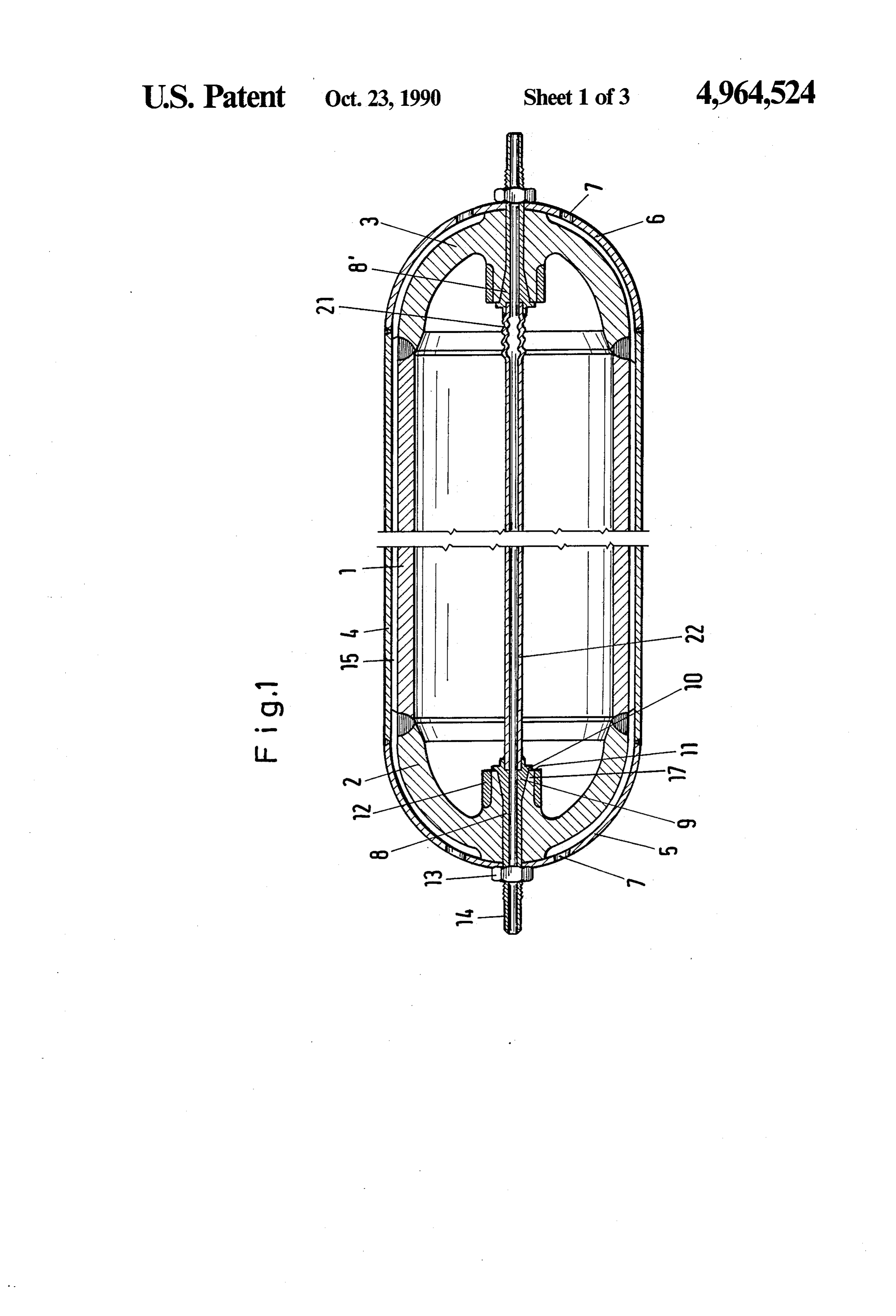
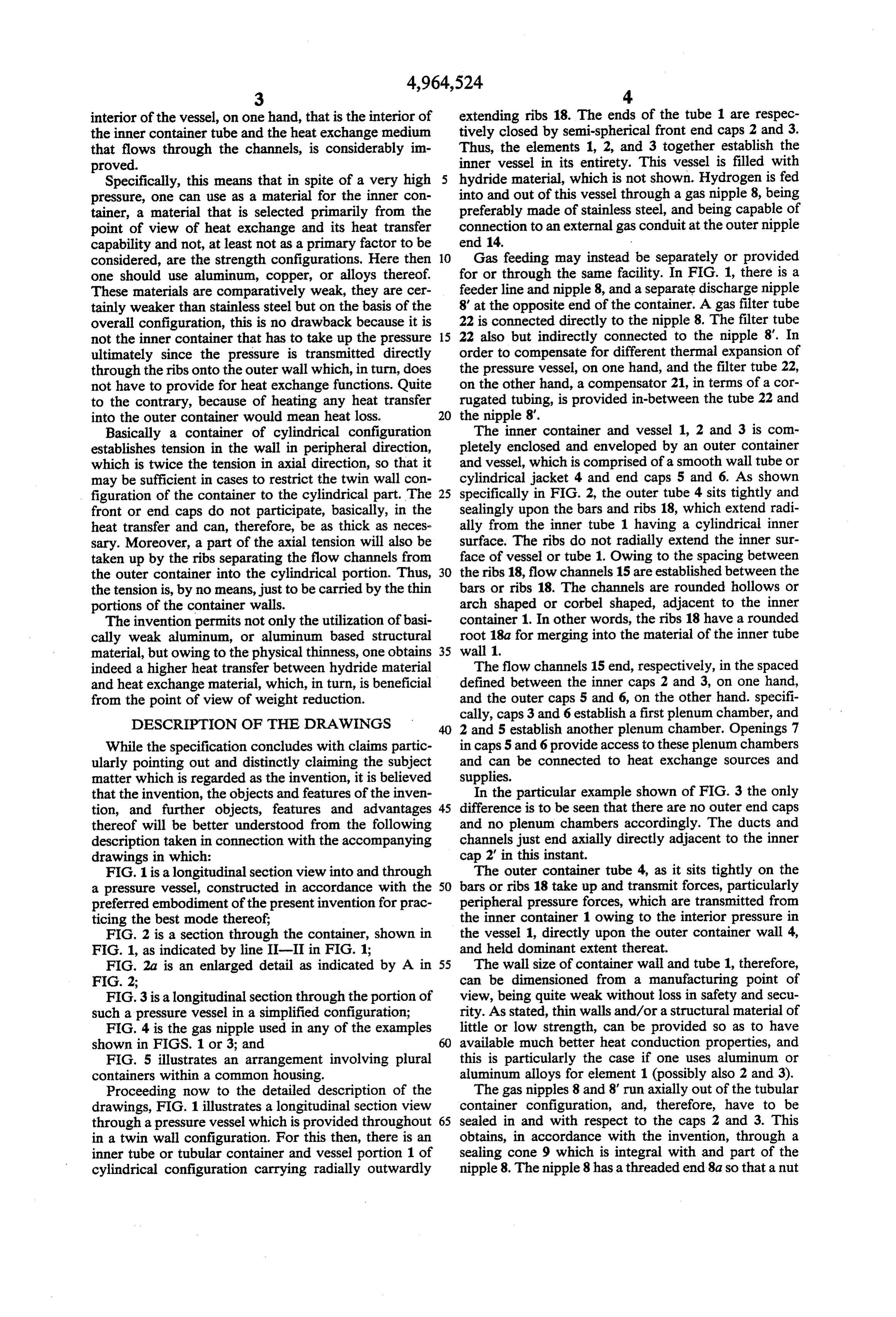
interior of the vessel, on one hand, that is the interior of extending ribs 18. The ends of the tube 1 are respec the inner container tube and the heat exchange medium tively closed by semi-spherical front end caps 2 and 3. that flows through the channels, is considerably im Thus, the elements 1, 2, and 3 together establish the proved. inner vessel in its entirety. This vessel is filled with Specifically, this means that in spite of a very high hydride material, which is not shown. Hydrogen is fed pressure, one can use as a material for the inner con into and out of this vessel through a gas nipple 8, being tainer, a material that is selected primarily from the preferably made of stainless steel, and being capable of point of view of heat exchange and its heat transfer connection to an external gas conduit at the outer nipple capability and not, at least not as a primary factor to be end 14.
considered, are the strength configurations. Here then Gas feeding may instead be separately or provided one should use aluminum, copper, or alloys thereof. for or through the same facility. In FIG. 1, there is a These materials are comparatively weak, they are cer feeder line and nipple 8, and a separate discharge nipple tainly weaker than stainless steel but on the basis of the 8' at the opposite end of the container. A gas filter tube overall configuration, this is no drawback because it is 22 is connected directly to the nipple 8. The filter tube not the inner container that has to take up the pressure 15 22 also but indirectly connected to the nipple 8'. In ultimately since the pressure is transmitted directly order to compensate for different thermal expansion of through the ribs onto the outer wall which, in turn, does the pressure vessel, on one hand, and the filter tube 22, not have to provide for heat exchange functions. Quite on the other hand, a compensator 21, in terms of a cor to the contrary, because of heating any heat transfer rugated tubing, is provided in-between the tube 22 and into the outer container would mean heat loss. 20 the nipple 8'.
Basically a container of cylindrical configuration The inner container and vessel 1, 2 and 3 is com establishes tension in the wall in peripheral direction, pletely enclosed and enveloped by an outer container which is twice the tension in axial direction, so that it and vessel, which is comprised of a smooth wall tube or may be sufficient in cases to restrict the twin wall con cylindrical jacket 4 and end caps 5 and 6. As shown figuration of the container to the cylindrical part. The 25 specifically in FIG. 2, the outer tube 4 sits tightly and front or end caps do not participate, basically, in the sealingly upon the bars and ribs 18, which extend radi heat transfer and can, therefore, be as thick as neces ally from the inner tube 1 having a cylindrical inner sary. Moreover, a part of the axial tension will also be surface. The ribs do not radially extend the inner sur taken up by the ribs separating the flow channels from face of vessel or tube 1. Owing to the spacing between the outer container into the cylindrical portion. Thus, 30 the ribs 18, flow channels 15 are established between the the tension is, by no means, just to be carried by the thin bars or ribs 18. The channels are rounded hollows or portions of the container walls. arch shaped or corbel shaped, adjacent to the inner The invention permits not only the utilization of basi container 1. In other words, the ribs 18 have a rounded cally weak aluminum, or aluminum based structural root 18a for merging into the material of the inner tube material, but owing to the physical thinness, one obtains 35 wall 1.
indeed a higher heat transfer between hydride material The flow channels 15 end, respectively, in the spaced and heat exchange material, which, in turn, is beneficial defined between the inner caps 2 and 3, on one hand, from the point of view of weight reduction. and the outer caps 5 and 6, on the other hand. specifi
DESCRIPTION OF THE DRAWINGS
cally, caps 3 and 6 establish a first plenum chamber, and 2 and 5 establish another plenum chamber. Openings 7
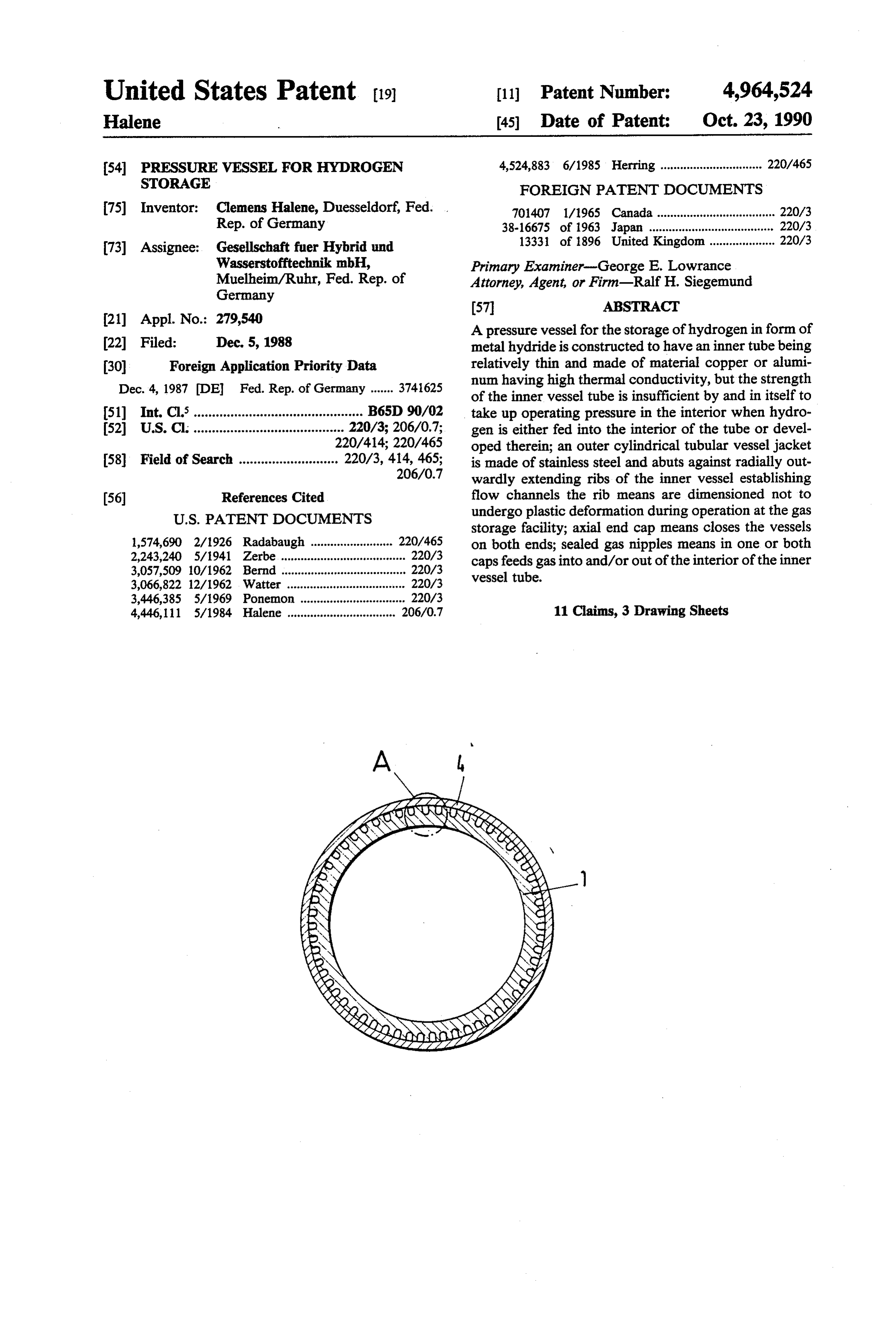
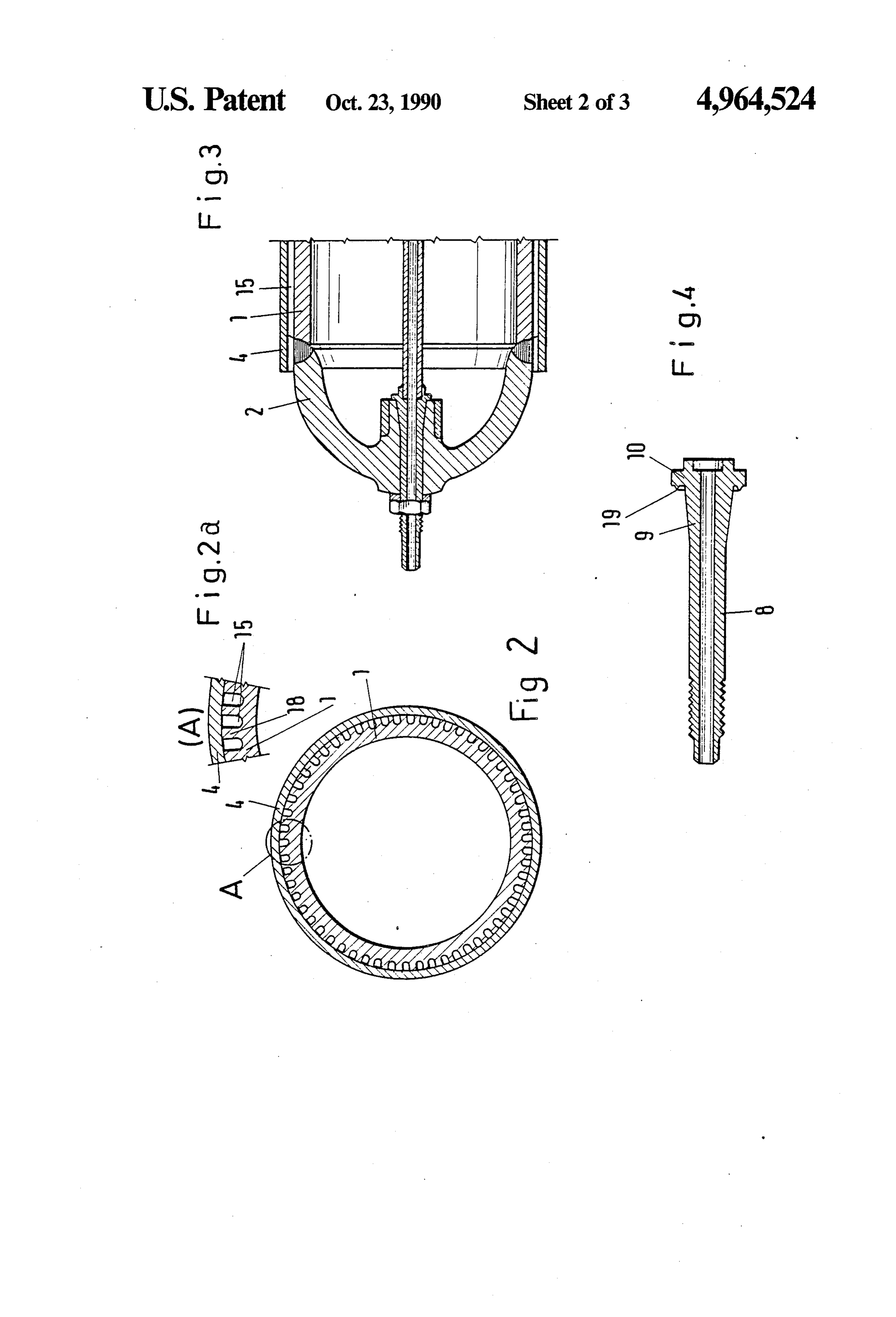
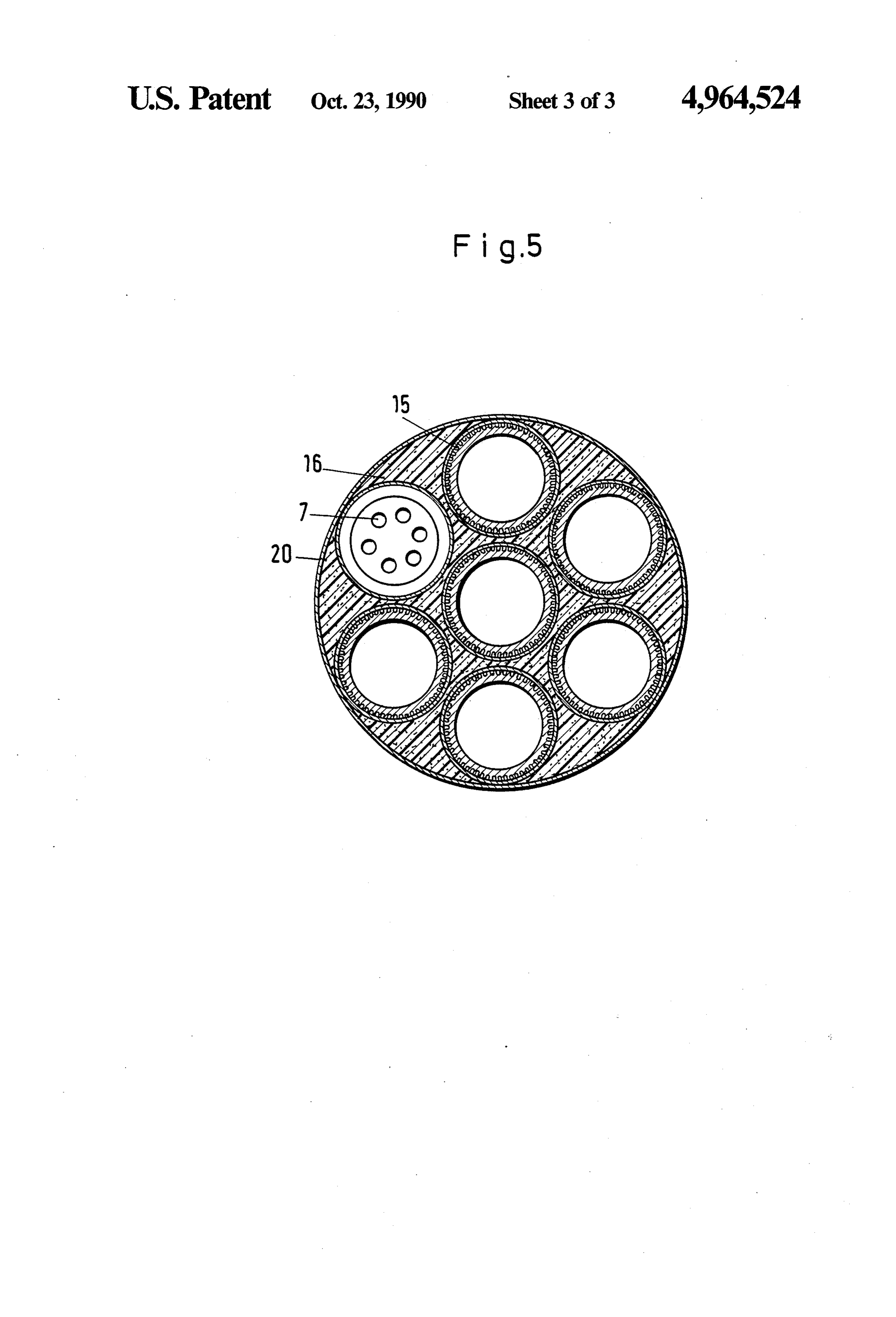
While the specification concludes with claims partic in caps 5 and 6 provide access to these plenum chambers ularly pointing out and distinctly claiming the subject and can be connected to heat exchange sources and matter which is regarded as the invention, it is believed supplies.
that the invention, the objects and features of the inven In the particular example shown of FIG. 3 the only tion, and further objects, features and advantages 45 difference is to be seen that there are no outer end caps thereof will be better understood from the following and no plenum chambers accordingly. The ducts and description taken in connection with the accompanying channels just end axially directly adjacent to the inner drawings in which: cap 2" in this instant.
FIG. 1 is a longitudinal section view into and through The outer container tube 4, as it sits tightly on the a pressure vessel, constructed in accordance with the 50 bars or ribs 18 take up and transmit forces, particularly preferred embodiment of the present invention for prac peripheral pressure forces, which are transmitted from ticing the best mode thereof; the inner container 1 owing to the interior pressure in FIG. 2 is a section through the container, shown in the vessel 1, directly upon the outer container wall 4, FIG. 1, as indicated by line II-II in FIG. 1; and held dominant extent thereat. FIG. 2a is an enlarged detail as indicated by A in 55 The wall size of container wall and tube 1, therefore, FIG. 2; can be dimensioned from a manufacturing point of FIG. 3 is a longitudinal section through the portion of view, being quite weak without loss in safety and secu such a pressure vessel in a simplified configuration; rity. As stated, thin walls and/or a structural material of FIG. 4 is the gas nipple used in any of the examples little or low strength, can be provided so as to have shown in FIGS. 1 or 3; and 60 available much better heat conduction properties, and FIG. 5 illustrates an arrangement involving plural this is particularly the case if one uses aluminum or containers within a common housing. aluminum alloys for element 1 (possibly also 2 and 3). Proceeding now to the detailed description of the The gas nipples 8 and 8' run axially out of the tubular drawings, FIG. 1 illustrates a longitudinal section view container configuration, and, therefore, have to be through a pressure vessel which is provided throughout 65 sealed in and with respect to the caps 2 and 3. This in a twin wall configuration. For this then, there is an obtains, in accordance with the invention, through a inner tube or tubular container and vessel portion 1 of sealing cone 9 which is integral with and part of the cylindrical configuration carrying radially outwardly nipple 8. The nipple 8 has a threaded end 8a so that a nut
Page 7
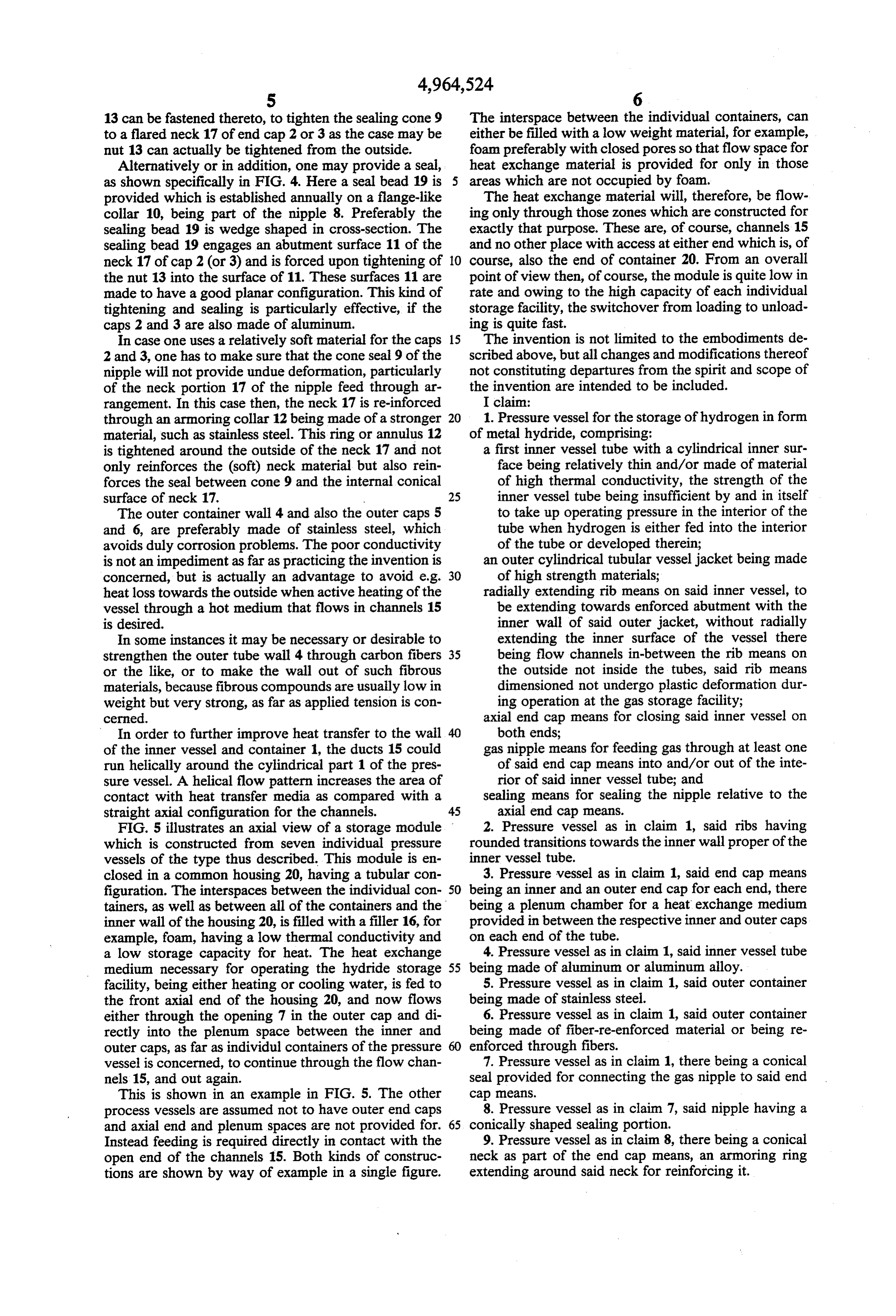
13 can be fastened thereto, to tighten the sealing cone 9 The interspace between the individual containers, can to a flared neck 17 of end cap 2 or 3 as the case may be either be filled with a low weight material, for example, nut 13 can actually be tightened from the outside. foam preferably with closed pores so that flow space for Alternatively or in addition, one may provide a seal, heat exchange material is provided for only in those as shown specifically in FIG. 4. Here a seal bead 19 is 5 areas which are not occupied by foam. provided which is established annually on a flange-like The heat exchange material will, therefore, be flow collar 10, being part of the nipple 8. Preferably the ing only through those zones which are constructed for sealing bead 19 is wedge shaped in cross-section. The exactly that purpose. These are, of course, channels 15 sealing bead 19 engages an abutment surface 11 of the and no other place with access at either end which is, of neck 17 of cap 2 (or 3) and is forced upon tightening of O course, also the end of container 20. From an overall the nut 13 into the surface of 11. These surfaces 11 are point of view then, of course, the module is quite low in made to have a good planar configuration. This kind of rate and owing to the high capacity of each individual tightening and sealing is particularly effective, if the storage facility, the switchover from loading to unload caps 2 and 3 are also made of aluminum. ing is quite fast.
In case one uses a relatively soft material for the caps 15 The invention is not limited to the embodiments de 2 and 3, one has to make sure that the cone seal 9 of the scribed above, but all changes and modifications thereof nipple will not provide undue deformation, particularly not constituting departures from the spirit and scope of of the neck portion 17 of the nipple feed through ar the invention are intended to be included. rangement. In this case then, the neck 17 is re-inforced I claim:
through an armoring collar 12 being made of a stronger 20 1. Pressure vessel for the storage of hydrogen in form material, such as stainless steel. This ring or annulus 12 of metal hydride, comprising:
is tightened around the outside of the neck 17 and not a first inner vessel tube with a cylindrical inner sur only reinforces the (soft) neck material but also rein face being relatively thin and/or made of material forces the seal between cone 9 and the internal conical of high thermal conductivity, the strength of the surface of neck 17. 25 inner vessel tube being insufficient by and in itself The outer container wall 4 and also the outer caps 5 to take up operating pressure in the interior of the and 6, are preferably made of stainless steel, which tube when hydrogen is either fed into the interior avoids duly corrosion problems. The poor conductivity of the tube or developed therein; is not an impediment as far as practicing the invention is an outer cylindrical tubular vesseljacket being made concerned, but is actually an advantage to avoid e.g. 30 of high strength materials; heat loss towards the outside when active heating of the radially extending rib means on said inner vessel, to vessel through a hot medium that flows in channels 15 be extending towards enforced abutment with the is desired. inner wall of said outer jacket, without radially In some instances it may be necessary or desirable to extending the inner surface of the vessel there strengthen the outer tube wall 4 through carbon fibers 35 being flow channels in-between the rib means on or the like, or to make the wall out of such fibrous the outside not inside the tubes, said rib means materials, because fibrous compounds are usually low in dimensioned not undergo plastic deformation dur weight but very strong, as far as applied tension is con ing operation at the gas storage facility; cerned. axial end cap means for closing said inner vessel on In order to further improve heat transfer to the wall 40 both ends;
of the inner vessel and container 1, the ducts 15 could gas nipple means for feeding gas through at least one run helically around the cylindrical part 1 of the pres of said end cap means into and/or out of the inte sure vessel. A helical flow pattern increases the area of rior of said inner vessel tube; and contact with heat transfer media as compared with a sealing means for sealing the nipple relative to the straight axial configuration for the channels. 45 axial end cap means.
FIG. 5 illustrates an axial view of a storage module 2. Pressure vessel as in claim 1, said ribs having which is constructed from seven individual pressure rounded transitions towards the inner wall proper of the vessels of the type thus described. This module is en inner vessel tube.
closed in a common housing 20, having a tubular con 3. Pressure vessel as in claim 1, said end cap means figuration. The interspaces between the individual con 50 being an inner and an outer end cap for each end, there tainers, as well as between all of the containers and the being a plenum chamber for a heat exchange medium inner wall of the housing 20, is filled with a filler 16, for provided in between the respective inner and outer caps example, foam, having a low thermal conductivity and on each end of the tube.
a low storage capacity for heat. The heat exchange 4. Pressure vessel as in claim 1, said inner vessel tube medium necessary for operating the hydride storage 55 being made of aluminum or aluminum alloy. facility, being either heating or cooling water, is fed to 5. Pressure vessel as in claim 1, said outer container the front axial end of the housing 20, and now flows being made of stainless steel.
either through the opening 7 in the outer cap and di 6. Pressure vessel as in claim 1, said outer container rectly into the plenum space between the inner and being made of fiber-re-enforced material or being re outer caps, as far as individul containers of the pressure 60 enforced through fibers.
vessel is concerned, to continue through the flow chan 7. Pressure vessel as in claim 1, there being a conical nels 15, and out again. seal provided for connecting the gas nipple to said end This is shown in an example in FIG. 5. The other cap means.
process vessels are assumed not to have outer end caps 8. Pressure vessel as in claim 7, said nipple having a and axial end and plenum spaces are not provided for. 65 conically shaped sealing portion.
Instead feeding is required directly in contact with the 9. Pressure vessel as in claim 8, there being a conical open end of the channels 15. Both kinds of construc neck as part of the end cap means, an armoring ring tions are shown by way of example in a single figure. extending around said neck for reinforcing it.
Page 8
10. Pressure vessel as in claim 1, the gas nipple being and in an assembled State is urged into a plane abutment on the inside of the cap means.
provided with a flange-like collar, being an annular 11. Pressure vessel as in claim 9, the neck being also bead arranged on that collar facing the end cap, the made of aluminum or an aluminum alloy. bead having a section which has a conical cross section 5 it it is
Provenance
- Collection
- Cited prior art
- Original PDF
- patentimages.storage.googleapis.com →
- Filed
- 1988-12-05
- Pages
- 8
- Method
- pdftotext (the PDF's own text layer) + pdftoppm 300dpi page scans
- Source
- Google Patents bibliographic record
- Granted
- 1990-10-23
- Inventors
- Clemens Halene; Gesellschaft fur Hybrid und Wasserstofftechnik mbH
- Transcribed from
- patentimages.storage.googleapis.com →