patent · US1262034
Hydro-oxygen generator.
9 April 1918
Page 1
Drawing sheet — no readable text.
Page 2
TED STATES PATENT OFFICE.
CHARLES H. FRAZIER, OF COLUMBUS, OHIO.
HYDRO-OXYGEN GENERATOR.
saasaakasa
Specification of Letters Patent, Patented Apr. 9, 1918.
Application filed June 30, 1916. Serial No. 106,987.
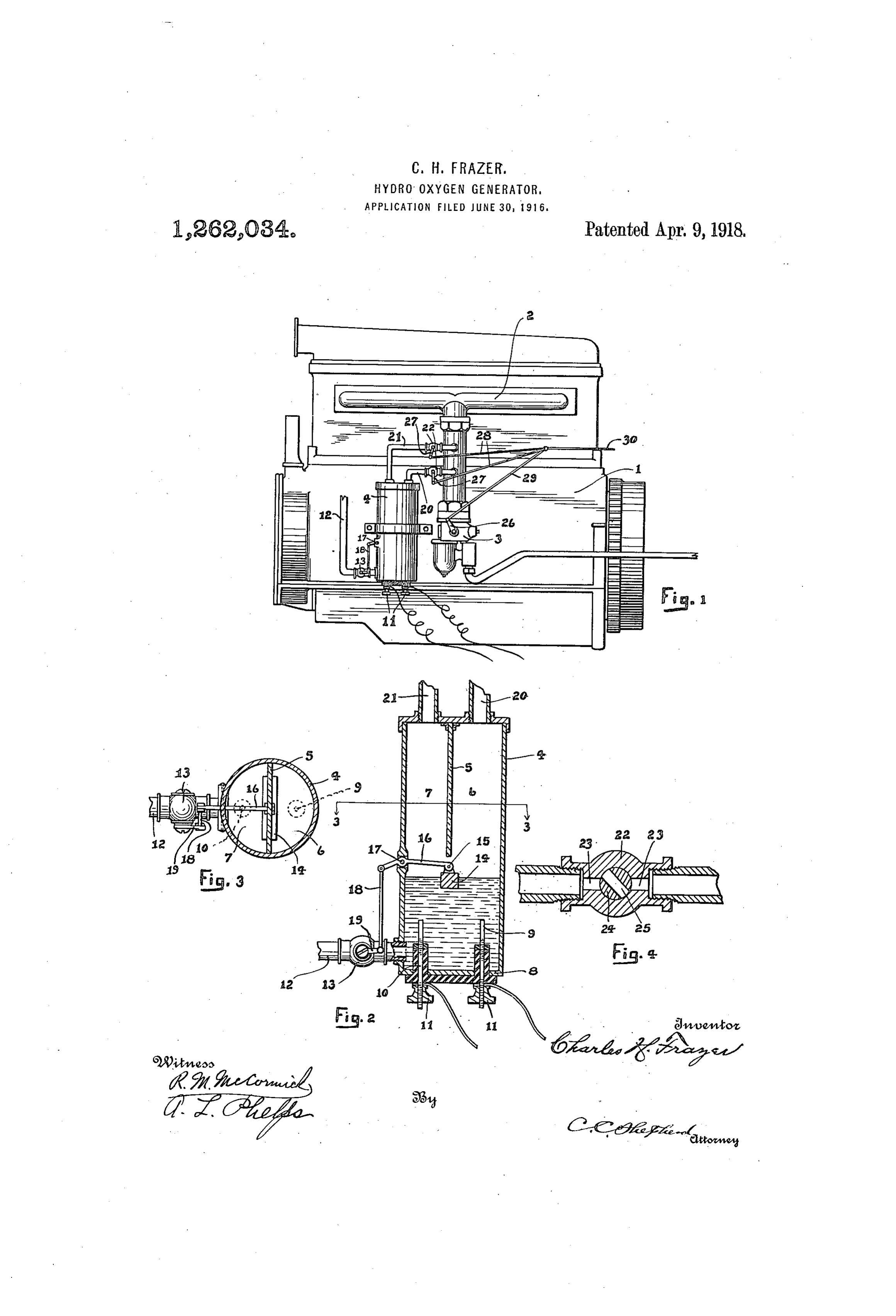
To all whom it may concern: a transverse wall 5 to form compartments 6 Be it known that I, CHARLEs H. FRAZER, and 7. The upper and lower ends of the a citizen of the United States, residing at generator tank are closed and located in the 60 lower wall 8 thereof are a pair of electrodes,
Columbus, in the county of Franklin and the anode being designated by the reference State of Ohio, have invented certain new numeral 9 and the cathode by the reference and useful Improvements in Hydro-Oxygen numeral 10.
Generators, of which the following is a centrally withBothrespect these electrodes are located to their respective
This invention relates to hydro-oxygen chambers 6 and 7. These electrodes are 65 mounted in the customary manner by being 0. generators for use with internal combustion insulated from each other, as is shown and engines. The attachment is designed par they are further adjustable up and down by ticularly to increase the efficiency of inter means of the adjusting nuts shown at 11. nal combustion engines, in that an addi tional quantity of oxygen is supplied where The lower portion of the tank 4 is in com 70 15 by complete combustion of the volatile hy munication with a source of water supply (not shown) by means of the supply pipe drocarbons is insured. By the use of my 12, flow through which is governed by means attachment, the heavy carbon deposited of the valve 13. The water level is normally 75 upon the cylinder and its coöperating parts maintained constant by operating the valve is also eliminated in that the carbon is com 13 through the medium of a float 14. This 20 pletely burned by the use of the additional float is pivotally attached as shown at 15 to Supply of oxygen. a lever 16 which lever is also pivotally at The main object of my invention resides tached intermediate its ends as shown at 17 in the provision of a tank wherein a pair of to the tank 4. The outside end of the lever 80 electrodes are provided for decomposing pivotally connects to a link 18 which latter 25 water into its constituent parts, together forms a direct connection with the valve with conduits leading from the tank to the arm shown at 19. Thus, when the water intake manifold, whereby the generated level in the tank 4 rises, the valve will be gases are permitted to enter the engine closed through the elevation of one end of 85 cylinder.
30 Still a further object of the present in the lever 16. When the current is turned on, vention resides in a controlling or throttling the tain water which, of course, contains a cer per cent of impurities to render it
Structure whereby the generated gases, as well as the hydrocarbon fuel may be simul either trolyte, acid or alkaline to serve as an elec 90 will be decomposed intoThese its gen con taneously throttled. stituents hydrogen and oxygen. 35 The preferred embodiment of my inven erated gases will bubble to the surface of . tion is shown in the accompanying sheet of the water within the generator and collect drawings, in which similar characters of in the compartments 6 and 7, hydrogen be 95 reference designate corresponding parts, and ing generated at the cathode and oxygen at in which: , the anode. These gases may then be con 40 Figure 1 is a view in side elevation of an ducted to the intake internal combustion engine showing mygen of pipes or conduits 20through and 21 the medium leading out erator mounted in position, of the top of the compartments 6 and 7 re 100 Fig. 2 is a vertical section on an enlarged spectfully. Each conduit is provided with scale of the generator shown in Fig. 1, a valve shown in cross section in Fig. 4 and 45 Fig. 3 is a transverse section taken on line comprising a body portion 22 having alin
Fig. 4 is a section through one of the con ing the passages 23. A plug 24 operates within body portion and is bored transversely trolling valves used in E. the sup as shown at 25, whereby when the passages 105 ply of gas to the intake manifol 23 and 25 are all in alinement, free flow of 50 In Fig. 1, the internal combustion engine isandrepresented by the reference numeral 1. ted. The flow the the is shown as being provided with a T throttled gases from
tanks 6 and 7 is permit these gases,themay alsoand
shaped intake manifold 2, which latter is by partially closing valves in communication with a carbureter 3. The the operation of these is preferably made 110 simultaneous with the throttle 26 of the car 55 generator itself comprises a circular tank 4 bureter 3. In order to provide this arrange whose upper portion is divided by means of
Page 3
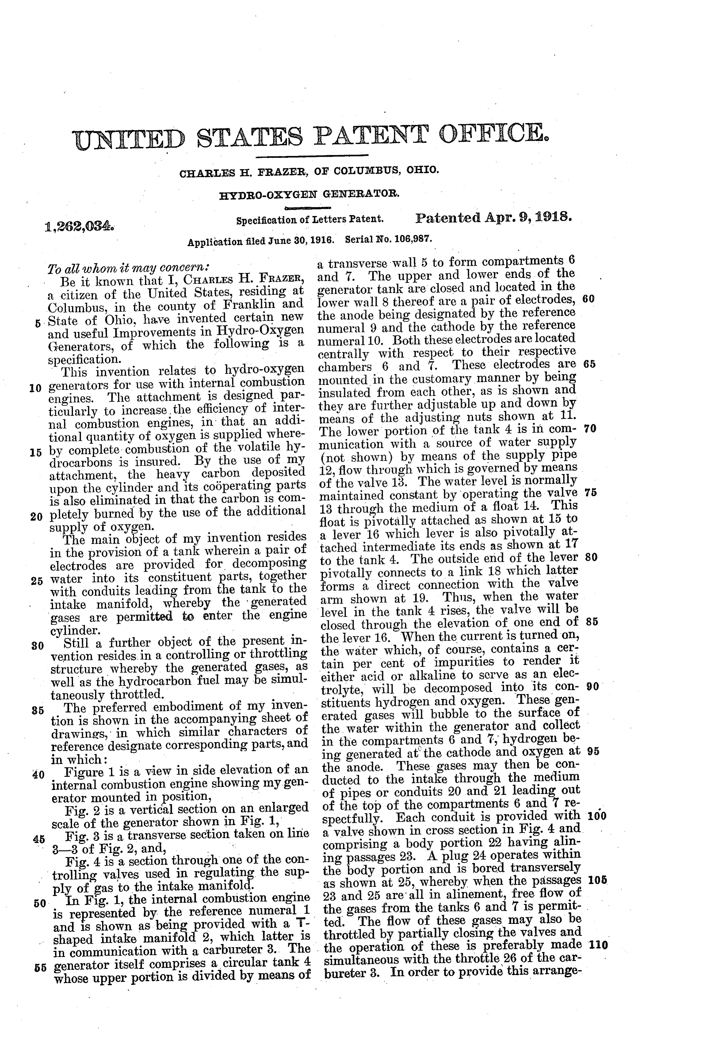
ment, each valve plug is provided with an tive electrodes in the lower portion of said operating arm 27 to each of which is piv tank, a water supply pipe leading into the otally connected a reach rod 28. A reach lower rod 29 is also connected to the arm of the tainingportion
of said tank, means for main constant level in said tank, and an throttle valve 26 and these are in turn piv outlet conduit leading otally connected with a common operating ment into said intake from between each compart the engine rod 30 leading to any convenient point of and carbureter.
operation, such as the dash of a motor ve 3. The combination with the intake of an 50 hicle, or preferably to the ordinary throttle internal combustion engine and its carbu 10 control mechanism.
reter, of a generator tank, a dividing wall
It will thus be apparent that when the dividing curernt is thrown on, hydrogen and oxygen a pair ofthe upper portion of said tank into compartments, positive and nega 5 will be generated by decomposing the water tive electrodes in the lower portion of said within the tank 4. These gases rise and are 15 collected in the chambers 7 and 6 from where tank, a water supply pipe leading into the lower portion of said tank, means for main they are permitted to enter the intake mani taining fold by passage through the pipes. 21 and let conduit a constant level in said tank, an out 20. The flow through these pipes is regu into said intake leading from each compartment between the engine and car lated by the valve structure shown and 20 regulation of these valves is effected simul the bureter, a controlling valve in each of said . conduits, a throttle taneously with the engine throttle valve. and means for simultaneously valve for said intake, By the addition of the separate gases, I am all of said valves. controlling thus enabled to enrich any hydro-carbon 4. The combination with the intake of an fuel which the carbureter may handle. In 25 this manner, a very low grade fuel may be internal combustion engine and its carbu reter, of means for generating hydrogen and used and by properly setting the valves 22, oxygen, the proper supply of gases may be added to to said intake and means for leading said gases render the fuel thoroughly combustible. bureter.
between the engine and car
What I claim, is:
30 1. The combination with the intake of an 5. The combination with the intake of an internal internal combustion engine, and its carbu reter, means combustion engine and its carbu reter, of a generator, tank, positive and neg water into hydrogen for electrically decomposing ative electrodes within said tank, a water leading said gases to said and oxygen, means for supply pipe leading to said tank, means for intake between the 35 maintaining a constant level in said tank, engine and carbureter, and means for regu lating and a pair of outlet conduits leading from said intake. the amount of flow of said gases to said tank to said intake between the engine In testimony whereof I affix my signature s and carbureter.
2. The combination with the intake of an presence of two witnesses.
40 internal combustion engine and its carbu reter, of a generator tank, a dividing wall Witnesses: / CHARLES H. FRAZER.
dividing the upper portion of said tank into C. C. SHEPHERD, . . a pair of compartments, positive and nega A. L. PHELPs.
Provenance
- Collection
- Cited prior art
- Original PDF
- patentimages.storage.googleapis.com →
- Filed
- 1916-06-30
- Pages
- 3
- Method
- pdftotext (the PDF's own text layer) + pdftoppm 300dpi page scans
- Source
- Google Patents bibliographic record
- Granted
- 1918-04-09
- Inventors
- Charles H Frazer
- Transcribed from
- patentimages.storage.googleapis.com →