patent · US4923768
Fuel cell power generation system
8 May 1990
Page 1 — bibliographic record
United States Patent (19) 11 Patent Number: 4,923,768 Kaneko et al. 45 Date of Patent: May 8, 1990 54 FUEL CELLPOWER GENERATIONSYSTEM 4,683,77 7/1987 Kinoshita et al. .................... 429/26 4,686,157 8/1987 Miyake et al. ........................ 429/19 75 Inventors: Hideo Kaneko, Yokohama; Hideo 4,738,903 4/1988 Garow et al. ....... 429/19 X Nishigaki, Ichihara, both of Japan 4,759,997 7/1988 Ohyauchi et al. .................... 429/19 4,838,020 6/1989 Fujitsuka .......................... 429/13 X 73) Assignee: Fuji Electric Co., Ltd., Japan
Primary Examiner-Anthony Skapars 21 Appl. No.: 395,260 Attorney, Agent, or Firm-Brumbaugh, Graves, 22 Filed: Aug. 17, 1989 Donohue & Raymond (30) Foreign Application Priority Data 57 ABSTRACT Aug. 22, 1988 JP Japan ................................ 63-207897 In order to improve the efficiency of a fuel cell power 51 Int. Cl. .............................................. H01M 8/06 generation system and its ability to adjust to disturbing 52 U.S. Cl. ........................................ 429/19; 429/25; factors which may occur during operation, a motor 429/26 driven compressor for providing reaction air to the fuel 58) Field of Search ......... 429/19, 17, 13, 26, cell system is driven independently of a power recovery 429/12, 20, 25, 34 system which recovers energy lost in operational by products and converts the energy into electrical power.
56) References Cited The independent motor driven compressor provides a
3,976,507 8/1976 Bloomfield ....................... 429/19 X. shortening the time necessary for system start up. 4,128,700 12/1978 Sederquist ............................. 429/17 4,622,275 11/1986 Noguchi et al. ...................... 429/19 9 Claims, 2 Drawing Sheets
Page 2
Drawing sheet — no readable text.
Page 3
Drawing sheet — no readable text.
Page 4
has reached its operating level, the power output of the
FUEL CELL POWER GENERATION SYSTEM fuel cell is coupled to the power system. Fuel cell power generation systems of the prior art
BACKGROUND OF THE INVENTION are subject to certain problems. Namely, the power The present invention relates to a fuel cell power 5 generation system of the prior art provides input energy generation system combining a fuel cell and a fuel re for the turbo compressor 3 by directing the exhaust gas former. A fuel cell generation system combines, as is from the combustion of the reformer 2 to the turbo well known, a fuel cell and a fuel reformer and gener compressor and forms a closed loop, as previously ex ates power by supplying both a fuel gas including a plained, by increasing the reaction air pressure to be large amount of hydrogen obtained, for example, by 10 supplied to the fuel cell 1 with the output of the com stream reformation of a natural gas and air extracted pressor. Therefore, if an interrelated control is not car from the atmosphere as an oxidizing agent to the fuel ried out in such a manner as to keep an adequate balance cell. in the flow rate, pressure, and temperature of fluids Development of a pressurized fuel cell power genera flowing into each section of the system, especially dur tion system, which is to be operated with a cell operat 15 ing start-up and stopping of the power generation sys ing pressure enhanced to about 4-7 kg/cm2G from tem and when disturbing factors such as variation of about 0.5 kg/cm2G in the prior art, has recently been load occur, the pressure distribution of the system as a continued with the objective of realizing improvement whole is changed and imbalances in pressure levels in the power generation efficiency of a fuel cell. within the fuel cell and surging of the turbo compressor Such a pressurized fuel cell power generation system 20 result, requires an air compressor for supplying pressurized air To avoid these effects, a prior art turbo-compressor extracted from the atmosphere to the fuel cell, and also has generally been operated at a constant pressure and requires a large power source to drive this compressor. flow rate in order to prevent surging of the turbo-com In order to improve efficiency of the power generation pressor and pressure variations and imbalances within system, a system has already been developed, and put 25 the fuel cell. However, if operation of the reformer 2 is into practical use, which utilizes heat in the system and controlled according to changes in load, the tempera exhaust gas from the reformer combustion as a power ture and pressure of the combustion exhaust gas used as source to drive a turbo compressor for pressurizing the a power source for the turbo-compressor 3 also reaction air.
changes. Moreover, the volume of air in the system
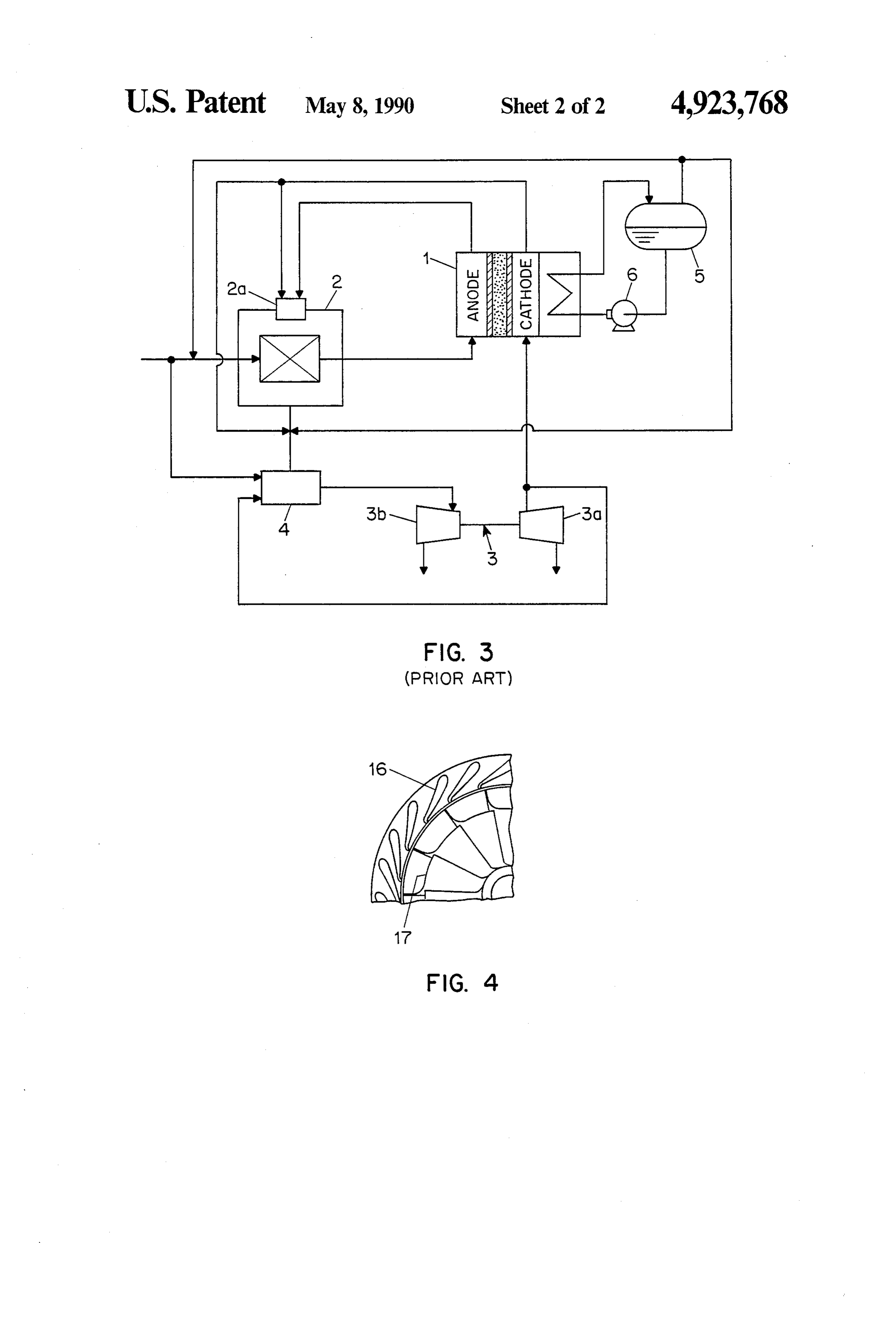
A process flowchart of a fuel cell power generation 30 functions system described previously as the prior art is shown in results in aasreduction a buffer for very fast changes of load and
FIG. 3. FIG. 3 illustrates, among other things, a fuel the turbo-compressorinwithin the flow rate of exhaust gas to a short period. Accord cell 1, a reformer 2, a turbo-compressor 3, an extra ingly, if countermeasures are not taken, energy to drive combustion chamber 4, a steam separator 5 and a pump the exhaust turbine 3b of the turbo-compressor 3 be 6 which circulates cooling water through the fuel cell, comes insufficient when a load change occurs. Espe
and the steam separator 5.
In FIG. 3, the natural gas used as a raw material for cially, in a partial load, the outlet pressure of the com pressor 3b changes and causes the reaction air pressure reforming is steam-reformed by the reformer 2 and is being supplied to the fuel cell to be reduced. This results then supplied, as fuel gas including a large amount of hydrogen, to a gas space in the anode side of the fuel 40 in pressure differences within the fuel cell which are cell 1. The reaction air, as the oxidating agent, is pres likely to damage the fuel cell. surized by a compressor 3a of the turbo-compressor 3 The insufficient source of power for the turbocom and is then supplied to a gas space in the cathode side of pressor 3 during a partial load has been addressed by the fuel cell 1, thereby enabling fuel cell 1 to generate employing a means of raising the temperature of the electrical power. The off fuel gas and off air exhausted 45 combustion exhaust gas of the reformer by inputting from the fuel cell 1 are supplied to a burner 2a of the extra steam and supplying a fuel such as natural gas to reformer 2. These gases are burned to provide the nec an extra combustion chamber 4, as is shown in FIG. 3. essary reforming reaction heat. The steam required for However, even though the fuel cell itself has a higher the reforming reaction is obtained from the steam sepa power generation efficiency in the partial load opera rator 5. Moreover, as a driving source of turbine 3b of 50 tion, the system mentioned above, which employs an the turbo-compressor 3, high temperature off air ex extra combustion chamber 4 in order to compensate for hausted from the fuel cell and extra high temperature insufficient power energy of the turbo-compressor 3, steam, obtained by heating excess steam from the steam will result in a lowered power generation efficiency of separator 5, are added to the combustion exhaust gas of the power generation system as a whole because of the the pressurized combustion furnace of reformer 2. This 55 energy consumed in operating the added chamber 4. combination of high temperature and high pressure Moreover, from the point of view of the operation of fluids is further heated in the extra combustion chamber the power generation system, employment of a turbo 4 and is used to drive the turbocompressor 3 by guiding compressor requires another external or supplemental the extra combustion chamber exhaust gas to a turbine air source for starting the turbo-compressor, and the 3b. 60 reaction air cannot be supplied to the fuel cell 1 until The power generation system can be started by the after the turbo-compressor 3 has started operation. following procedures. The burner of reformer 2 is first Moreover, the turbo-compressor requires, in general, fired in order to raise the furnace temperature and pres careful starting operation in order to prevent surging, sure up to a predetermined value. The turbo-compres thus it takes a considerable period until reaction air sor 3 is then started by air supplied from an air source pressure is raised up to the rated pressure. As a result, it provided separately or externally and power generation is considered a factor in lengthening the starting time of is started by supplying fuel gas and air to the fuel cell 1. the power generation system and also in limiting the Upon confirmation that the fuel cell operation voltage ability to respond to load variations.
Page 5
SUMMARY OF THE INVENTION load operation can also be lowered by control of the drive motor and the partial load efficiency can be im
It is an object of the present invention to provide a proved.
fuel cell power generation system which enhances re The variable nozzle provided in the inlet side of gas sponse to load variations by preventing disturbances to turbine is adjusted so that deterioration of gas turbine the reaction air system by factors such as system start characteristics due to the change of inflow gas quantity up and variation of load. A further object of the present resulting from changes in operational load can be mini invention is to improve power generation efficiency of mized. As a result, the collecting power of the gas tur the system as a whole by providing a stable supply of bine can be improved and the partial load efficiency can pressurized air, particularly during start-up and load 10 also be improved.
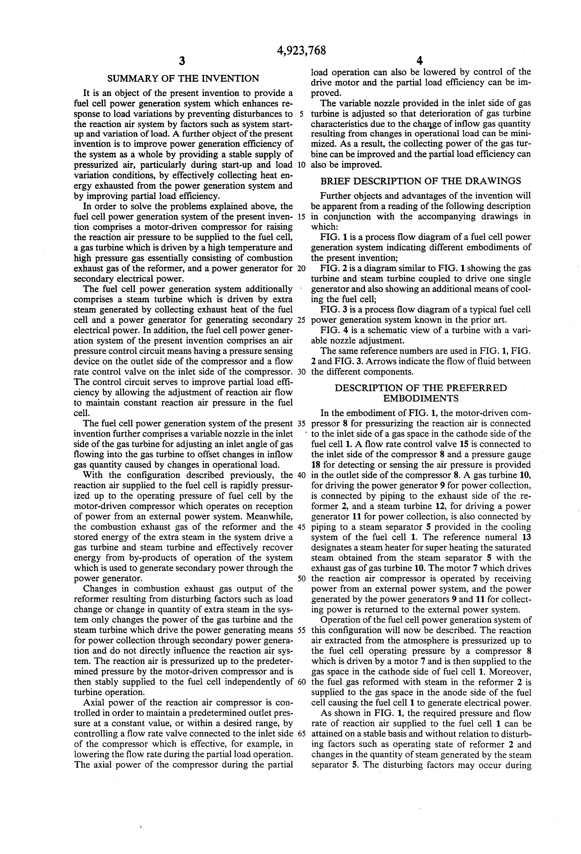
variation conditions, by effectively collecting heat en BRIEF DESCRIPTION OF THE DRAWINGS ergy exhausted from the power generation system and by improving partial load efficiency. Further objects and advantages of the invention will In order to solve the problems explained above, the be apparent from a reading of the following description fuel cell power generation system of the present inven 15 in conjunction with the accompanying drawings in tion comprises a motor-driven compressor for raising which:
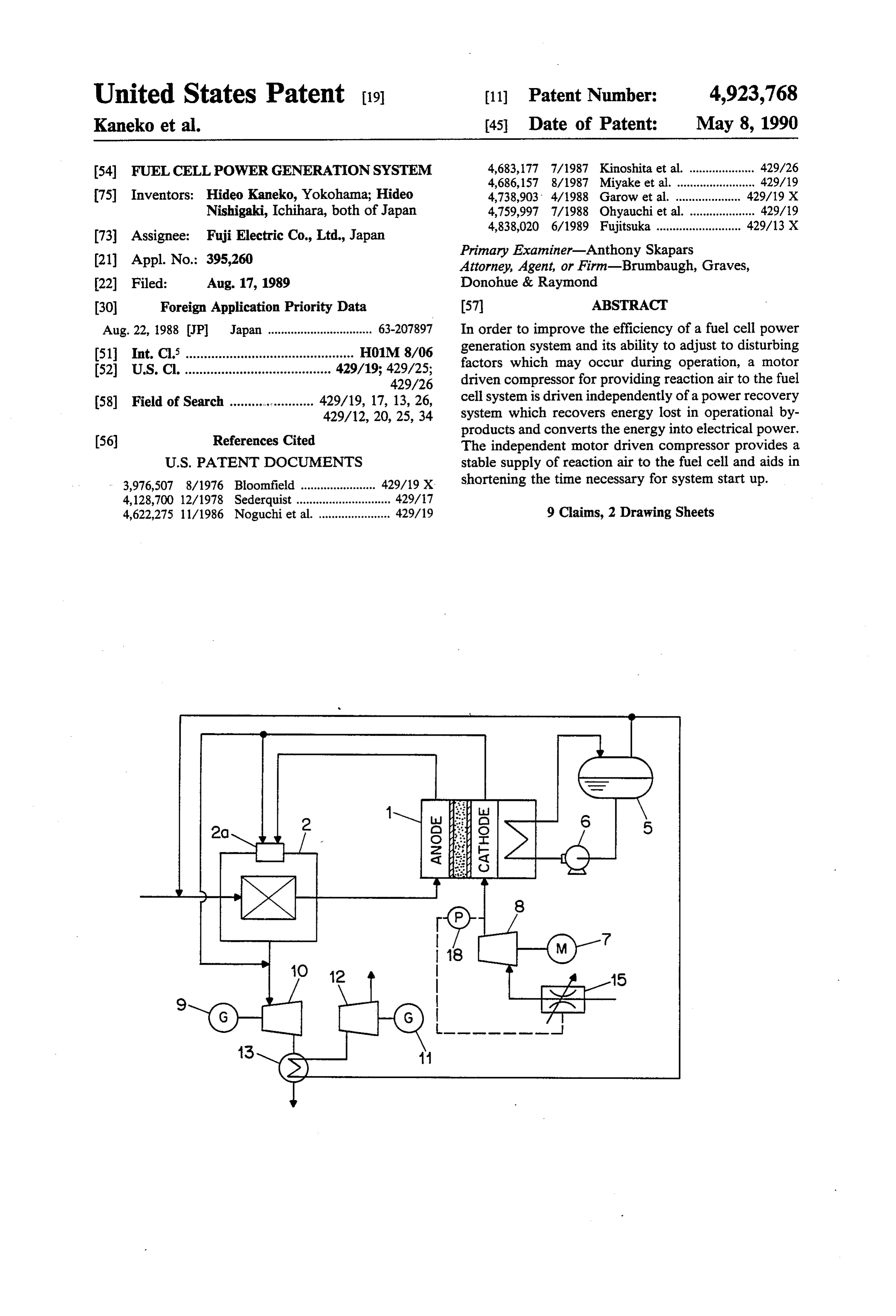
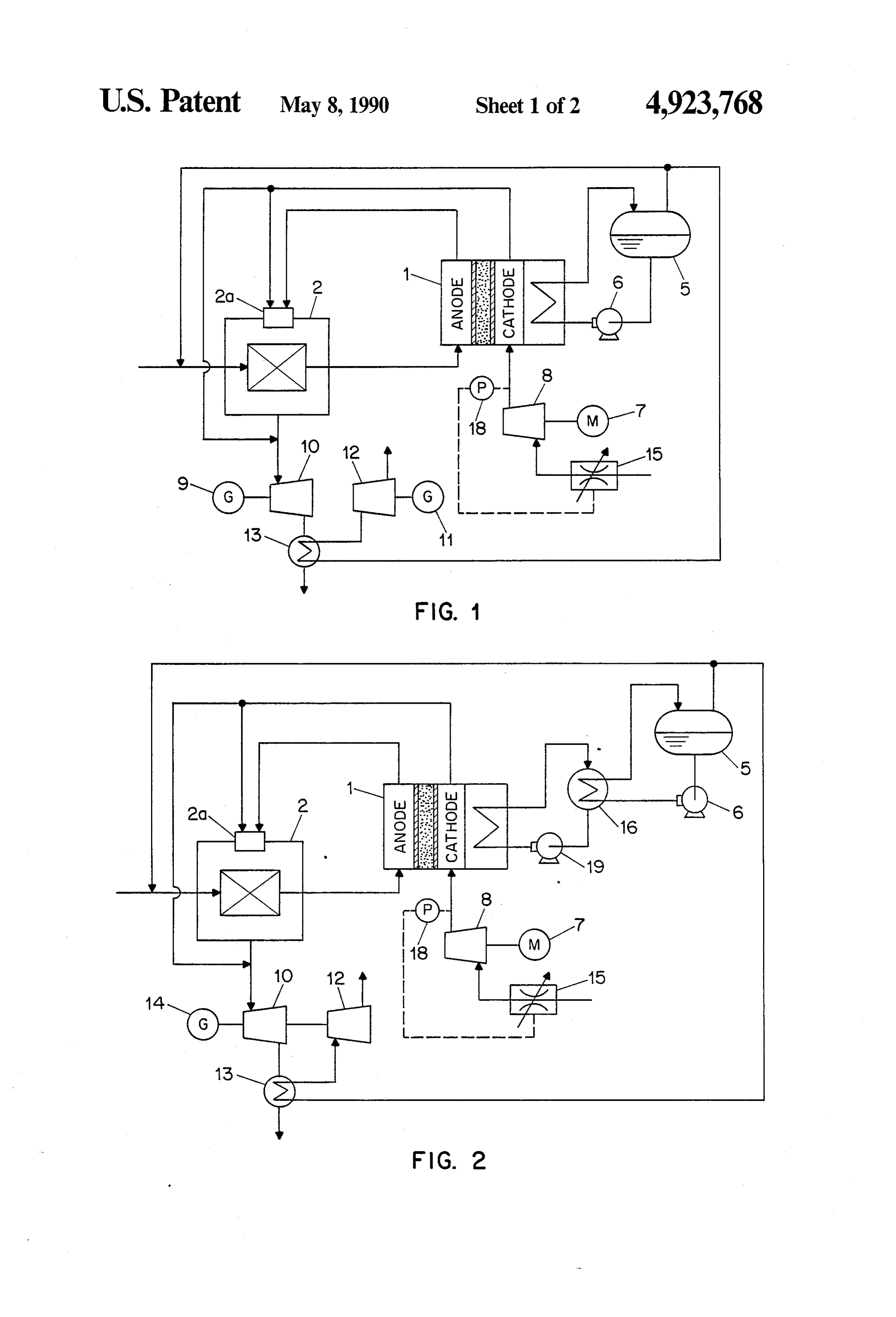
the reaction air pressure to be supplied to the fuel cell, FIG. 1 is a process flow diagram of a fuel cell power a gas turbine which is driven by a high temperature and generation system indicating different embodiments of high pressure gas essentially consisting of combustion the present invention;
exhaust gas of the reformer, and a power generator for 20 FIG. 2 is a diagram similar to FIG. 1 showing the gas secondary electrical power. turbine and steam turbine coupled to drive one single The fuel cell power generation system additionally generator and also showing an additional means of cool comprises a steam turbine which is driven by extra ing the fuel cell;
steam generated by collecting exhaust heat of the fuel FIG. 3 is a process flow diagram of a typical fuel cell cell and a power generator for generating secondary 25 power generation system known in the prior art. electrical power. In addition, the fuel cell power gener FIG. 4 is a schematic view of a turbine with a vari ation system of the present invention comprises an air able nozzle adjustment.
pressure control circuit means having a pressure sensing The same reference numbers are used in FIG. 1, FIG. device on the outlet side of the compressor and a flow 2 and FIG. 3. Arrows indicate the flow of fluid between rate control valve on the inlet side of the compressor. 30 the different components.
The control circuit serves to improve partial load effi DESCRIPTION OF THE PREFERRED ciency by allowing the adjustment of reaction air flow EMBODIMENTS to maintain constant reaction air pressure in the fuel cell. In the embodiment of FIG. 1, the motor-driven com The fuel cell power generation system of the present 35 pressor 8 for pressurizing the reaction air is connected invention further comprises a variable nozzle in the inlet to the inlet side of a gas space in the cathode side of the side of the gas turbine for adjusting an inlet angle of gas fuel cell 1. A flow rate control valve 15 is connected to flowing into the gas turbine to offset changes in inflow the inlet side of the compressor 8 and a pressure gauge gas quantity caused by changes in operational load. 18 for detecting or sensing the air pressure is provided With the configuration described previously, the 40 in the outlet side of the compressor 8. A gas turbine 10, reaction air supplied to the fuel cell is rapidly pressur for driving the power generator 9 for power collection, ized up to the operating pressure of fuel cell by the is connected by piping to the exhaust side of the re motor-driven compressor which operates on reception former 2, and a steam turbine 12, for driving a power of power from an external power system. Meanwhile, generator 11 for power collection, is also connected by the combustion exhaust gas of the reformer and the 45 piping to a steam separator 5 provided in the cooling stored energy of the extra steam in the system drive a system of the fuel cell 1. The reference numeral 13 gas turbine and steam turbine and effectively recover designates a steam heater for super heating the saturated energy from by-products of operation of the system steam obtained from the steam separator 5 with the which is used to generate secondary power through the exhaust gas of gas turbine 10. The motor 7 which drives power generator. 50 the reaction air compressor is operated by receiving Changes in combustion exhaust gas output of the power from an external power system, and the power reformer resulting from disturbing factors such as load generated by the power generators 9 and 11 for collect change or change in quantity of extra steam in the sys ing power is returned to the external power system. tem only changes the power of the gas turbine and the Operation of the fuel cell power generation system of steam turbine which drive the power generating means 55 this configuration will now be described. The reaction for power collection through secondary power genera air extracted from the atmosphere is pressurized up to tion and do not directly influence the reaction air sys the fuel cell operating pressure by a compressor 8 tem. The reaction air is pressurized up to the predeter which is driven by a motor 7 and is then supplied to the mined pressure by the motor-driven compressor and is gas space in the cathode side of fuel cell 1. Moreover, then stably supplied to the fuel cell independently of 60 the fuel gas reformed with steam in the reformer 2 is turbine operation. supplied to the gas space in the anode side of the fuel Axial power of the reaction air compressor is con cell causing the fuel cell 1 to generate electrical power. trolled in order to maintain a predetermined outlet pres As shown in FIG. 1, the required pressure and flow sure at a constant value, or within a desired range, by rate of reaction air supplied to the fuel cell 1 can be controlling a flow rate valve connected to the inlet side 65 attained on a stable basis and without relation to disturb of the compressor which is effective, for example, in ing factors such as operating state of reformer 2 and lowering the flow rate during the partial load operation. changes in the quantity of steam generated by the steam The axial power of the compressor during the partial separator 5. The disturbing factors may occur during
Page 6
operation of the power generation system but particu ing system which has high corrosion resistance and heat larly may occur during start-up and load variations. conductivity.
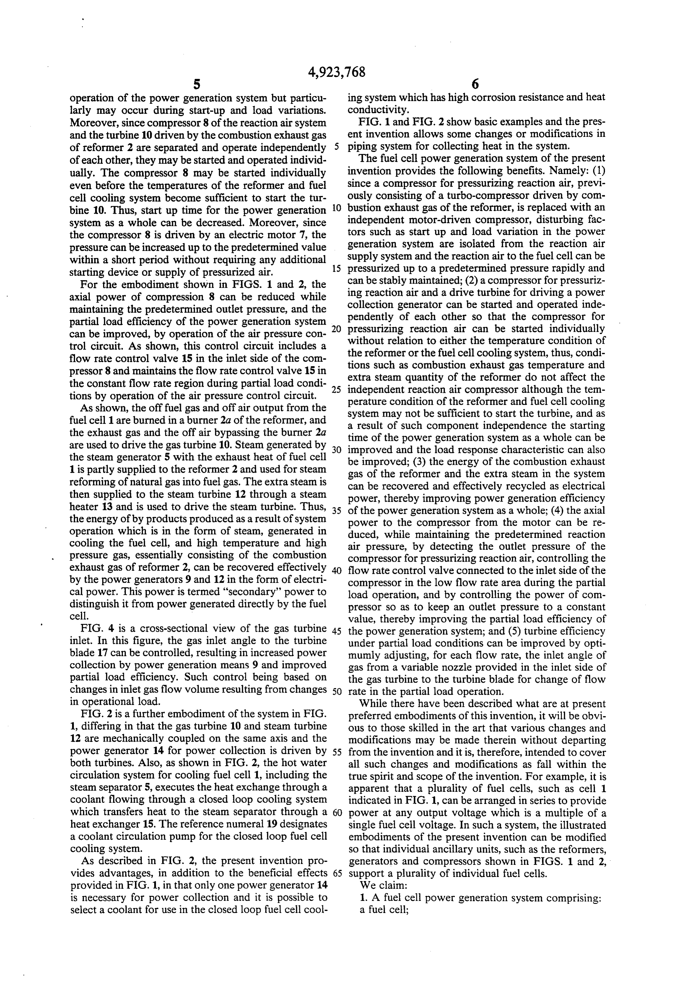
Moreover, since compressor 8 of the reaction air system FIG. 1 and FIG. 2 show basic examples and the pres and the turbine 10 driven by the combustion exhaust gas ent invention allows some changes or modifications in of reformer 2 are separated and operate independently piping system for collecting heat in the system. of each other, they may be started and operated individ The fuel cell power generation system of the present ually. The compressor 8 may be started individually invention provides the following benefits. Namely: (1) even before the temperatures of the reformer and fuel since a compressor for pressurizing reaction air, previ cell cooling system become sufficient to start the tur ously consisting of a turbo-compressor driven by com bine 10. Thus, start up time for the power generation 10 bustion exhaust gas of the reformer, is replaced with an system as a whole can be decreased. Moreover, since independent motor-driven compressor, disturbing fac the compressor 8 is driven by an electric motor 7, the tors such as start up and load variation in the power pressure can be increased up to the predetermined value generation system are isolated from the reaction air within a short period without requiring any additional 15 supply system and the reaction air to the fuel cell can be pressurized up to a predetermined pressure rapidly and starting device or supply of pressurized air.
For the embodiment shown in FIGS. 1 and 2, the can be stably maintained; (2) a compressor for pressuriz ing axial power of compression 8 can be reduced while collection reaction air and a drive turbine for driving a power maintaining the predetermined outlet pressure, and the pendently generator can be started and operated inde partial load efficiency of the power generation system 20 pressurizing reaction air so of each other that the compressor for can be started individually can be improved, by operation of the air pressure con without relation to either the temperature condition of trol circuit. As shown, this control circuit includes a the reformer or the fuel cell cooling system, thus, condi flow rate control valve 15 in the inlet side of the com pressor 8 and maintains the flow rate control valve 15 in tions such as combustion exhaust gas temperature and extra steam quantity of the reformer do not affect the the constant flow rate region during partial load condi 25 independent reaction air compressor although the tem tions by operation of the air pressure control circuit.
As shown, the off fuel gas and off air output from the perature condition of the reformer and fuel cell cooling system may not be sufficient to start the turbine, and as fuel cell 1 are burned in a burner 2a of the reformer, and a result of such component independence the starting the exhaust gas and the off air bypassing the burner 2a time of the power generation system as a whole can be are used to drive the gas turbine 10. Steam generated by 30 the steam generator 5 with the exhaust heat of fuel cell improved and the load response characteristic can also be improved; (3) the energy of the combustion exhaust 1 is partly supplied to the reformer 2 and used for steam gas of the reformer and the extra steam in the system reforming of natural gas into fuel gas. The extra steam is can be recovered and effectively recycled as electrical then supplied to the steam turbine 12 through a steam power, thereby improving power generation efficiency heater 13 and is used to drive the steam turbine. Thus, 35 of the power generation system as a whole; (4) the axial the energy of by products produced as a result of system power to the compressor from the motor can be re operation which is in the form of steam, generated in duced, while maintaining the predetermined reaction cooling the fuel cell, and high temperature and high air pressure, by detecting the outlet pressure of the pressure gas, essentially consisting of the combustion compressor for pressurizing reaction air, controlling the exhaust gas of reformer 2, can be recovered effectively flow rate control valve connected to the inlet side of the by the power generators 9 and 12 in the form of electri compressor in the low flow rate area during the partial cal power. This power is termed "secondary' power to load operation, and by controlling the power of com distinguish it from power generated directly by the fuel pressor so as to keep an outlet pressure to a constant cell. value, thereby improving the partial load efficiency of FIG. 4 is a cross-sectional view of the gas turbine 45 the power generation system; and (5) turbine efficiency inlet. In this figure, the gas inlet angle to the turbine under partial load conditions can be improved by opti blade 17 can be controlled, resulting in increased power mumly adjusting, for each flow rate, the inlet angle of collection by power generation means 9 and improved gas from a variable nozzle provided in the inlet side of partial load efficiency. Such control being based on the gas turbine to the turbine blade for change of flow changes in inlet gas flow volume resulting from changes 50 rate in the partial load operation. in operational load. While there have been described what are at present FIG. 2 is a further embodiment of the system in FIG. preferred embodiments of this invention, it will be obvi 1, differing in that the gas turbine 10 and steam turbine ous to those skilled in the art that various changes and 12 are mechanically coupled on the same axis and the modifications may be made therein without departing power generator 14 for power collection is driven by 55 from the invention and it is, therefore, intended to cover both turbines. Also, as shown in FIG. 2, the hot water all such changes and modifications as fall within the circulation system for cooling fuel cell 1, including the true spirit and scope of the invention. For example, it is steam separator 5, executes the heat exchange through a apparent that a plurality of fuel cells, such as cell 1 coolant flowing through a closed loop cooling system indicated in FIG. 1, can be arranged in series to provide which transfers heat to the steam separator through a 60 power at any output voltage which is a multiple of a heat exchanger 15. The reference numeral 19 designates single fuel cell voltage. In such a system, the illustrated a coolant circulation pump for the closed loop fuel cell embodiments of the present invention can be modified cooling system. so that individual ancillary units, such as the reformers, As described in FIG. 2, the present invention pro generators and compressors shown in FIGS. 1 and 2, vides advantages, in addition to the beneficial effects 65 support a plurality of individual fuel cells. provided in FIG. 1, in that only one power generator 14 We claim:
is necessary for power collection and it is possible to 1. A fuel cell power generation system comprising: select a coolant for use in the closed loop fuel cell cool a fuel cell;
Page 7
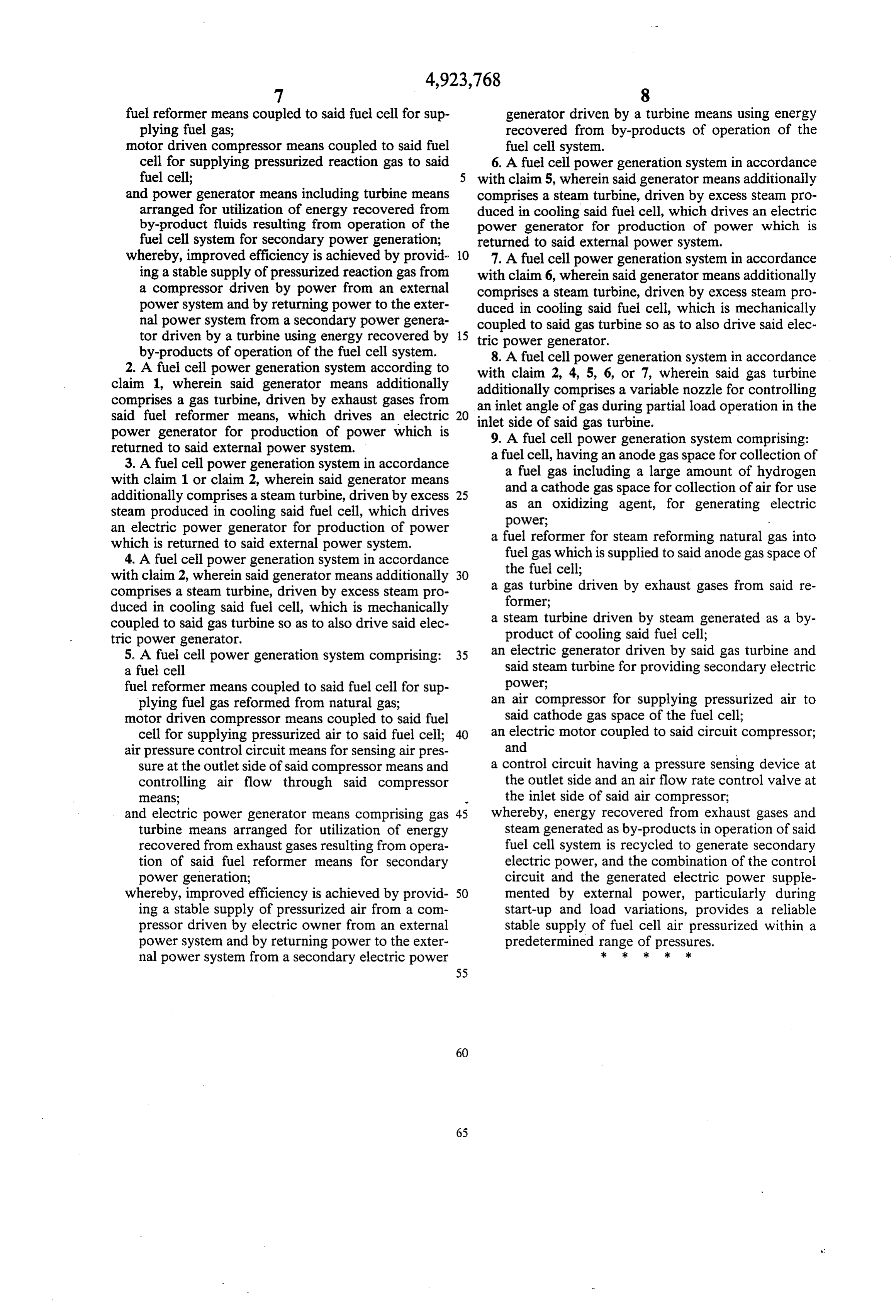
fuel reformer means coupled to said fuel cell for sup generator driven by a turbine means using energy plying fuel gas; recovered from by-products of operation of the motor driven compressor means coupled to said fuel fuel celi system.
cell for supplying pressurized reaction gas to said 6. A fuel cell power generation system in accordance fuel cell; 5 with claim 5, wherein said generator means additionally and power generator means including turbine means comprises a steam turbine, driven by excess steam pro arranged for utilization of energy recovered from duced in cooling said fuel cell, which drives an electric by-product fluids resulting from operation of the power generator for production of power which is fuel cell system for secondary power generation; returned to said external power system. whereby, improved efficiency is achieved by provid 10 7. A fuel cell power generation system in accordance ing a stable supply of pressurized reaction gas from with claim 6, wherein said generator means additionally a compressor driven by power from an external comprises a steam turbine, driven by excess steam pro power system and by returning power to the exter duced in cooling said fuel cell, which is mechanically nal power system from a secondary power genera coupled to said gas turbine so as to also drive said elec tor driven by a turbine using energy recovered by 15 tric power generator.
by-products of operation of the fuel cell system. 8. A fuel cell power generation system in accordance 2. A fuel cell power generation system according to with claim 2, 4, 5, 6, or 7, wherein said gas turbine claim 1, wherein said generator means additionally additionally comprises a variable nozzle for controlling comprises a gas turbine, driven by exhaust gases from an inlet angle of gas during partial load operation in the said fuel reformer means, which drives an electric 20 power generator for production of power which is inlet 9.
side of said gas turbine.
A fuel cell power generation system comprising:
returned to said external power system. a fuel cell, having an anode gas space for collection of 3. A fuel cell power generation system in accordance a fuel gas including a large amount of hydrogen with claim 1 or claim 2, wherein said generator means and a cathode gas space for collection of air for use additionally comprises a steam turbine, driven by excess 25 as an oxidizing agent, for generating electric steam produced in cooling said fuel cell, which drives power;
an electric power generator for production of power which is returned to said external power system. a fuel reformer for steam reforming natural gas into 4. A fuel cell power generation system in accordance fuel gas which is supplied to said anode gas space of with claim 2, wherein said generator means additionally 30 the fuel cell;
comprises a steam turbine, driven by excess steam pro a gas turbine driven by exhaust gases from said re duced in cooling said fuel cell, which is mechanically former;
coupled to said gas turbine so as to also drive said elec a steam turbine driven by steam generated as a by tric power generator. product of cooling said fuel cell; 5. A fuel cell power generation system comprising: 35 an electric generator driven by said gas turbine and a fuel cell said steam turbine for providing secondary electric fuel reformer means coupled to said fuel cell for sup power;
plying fuel gas reformed from natural gas; an air compressor for supplying pressurized air to motor driven compressor means coupled to said fuel said cathode gas space of the fuel cell; cell for supplying pressurized air to said fuel cell; 40 an electric motor coupled to said circuit compressor; air pressure control circuit means for sensing air pres and sure at the outlet side of said compressor means and a control circuit having a pressure sensing device at controlling air flow through said compressor the outlet side and an air flow rate control valve at means; the inlet side of said air compressor; and electric power generator means comprising gas whereby, energy recovered from exhaust gases and turbine means arranged for utilization of energy steam generated as by-products in operation of said recovered from exhaust gases resulting from opera fuel cell system is recycled to generate secondary tion of said fuel reformer means for secondary electric power, and the combination of the control power generation; circuit and the generated electric power supple whereby, improved efficiency is achieved by provid SO mented by external power, particularly during ing a stable supply of pressurized air from a com start-up and load variations, provides a reliable pressor driven by electric owner from an external stable supply of fuel cell air pressurized within a power system and by returning power to the exter predetermined range of pressures. nal power system from a secondary electric power sk : k ck s
Provenance
- Collection
- Cited prior art
- Original PDF
- patentimages.storage.googleapis.com →
- Filed
- 1989-08-17
- Pages
- 7
- Method
- pdftotext (the PDF's own text layer) + pdftoppm 300dpi page scans
- Source
- Google Patents bibliographic record
- Granted
- 1990-05-08
- Inventors
- Hideo Kaneko; Hideo Nishigaki; Fuji Electric Co Ltd
- Transcribed from
- patentimages.storage.googleapis.com →