patent · US4411223
Method of operating an I.C. engine
25 October 1983
Page 1 — bibliographic record
United States Patent (19) 11 4,411,223 Kiely 45) Oct. 25, 1983 54 METHOD OF OPERATING AN I.C. ENGINE 2608044 9/1977 Fed. Rep. of Germany. 76 Inventor: Martin Kiely, Airglooney, Tuam, 2808973 9/1979 Fed. Rep. of Germany. 123/DIG. 12 Co. Galway, Ireland 2327980 4/1977 France
(21) Appl. No.: 275,512 1513744 6/1978 United Kingdom.
22 Filed: Jun. 19, 1981 1561212 2/1980 United Kingdom . 30 Foreign Application Priority Data 1573601 8/1980 United Kingdom.
Jun. 20, 1980 (IE) Ireland ................................. 1292/80
May 14, 1981 IE Ireland................................. 1079/81 Primary Examiner-Charles J. Myhre 51) Int. Cl. ........................ F02B 43/08; F02B 75/12 Assistant Examiner-E. Rollins Cross 52 U.S. C. ....................................... 123/3; 123/1 A; Attorney, Agent, or Firm-Young & Thompson 123/25 E; 123/DIG. 12 (57) ABSTRACT
123/25 E, 575, 577 In fuel supply apparatus for an internal combustion engine, hydrogen gas is generated in a reaction vessel (56) References Cited by the reaction of an alkali or alkaline earth metal with
Re. 28,547 9/1975 Pacheco .................................. 123/3 engine. A vacuum-operated non-return valve admits 3,799,124 3/1974 Swain ......................... ... 123/1 A hydrogen gas from the reaction vessel to the duct when 3,818,875 6/1974 Phillips et al..................... 23/25 E the pressure at the engine intake is less than the pressure 3,862,624 1/1975 Underwood ... . 23/DIG. 12 in the reaction vessel. Air and optionally oxygen, also 3,946,711 3/1976 Wigal .................................. 123/536 pass to the engine intake through respective ducts. A 3,977,365 8/1976 Vierling et al.......................... 123/3 valve in each duct is interlinked with those in the other 4,016,836 4/1977 MacKay et al. ........................ 123/3 ducts and the valves control the flow of gas in the re
4,141,326 2/1979 Wolber ..................... 123/DIG. 12 spective ducts so that the flow of hydrogen to the en gine intake is in controlled proportion to the flows of air
FOREIGN PATENT DOCUMENTS and oxygen.
2525547 12/1976 Fed. Rep. of Germany . 12 Claims, 11 Drawing Figures
Page 2
Drawing sheet — no readable text.
Page 3
Drawing sheet — no readable text.
Page 4
Drawing sheet — no readable text.
Page 5
Drawing sheet — no readable text.
Page 6
Drawing sheet — no readable text.
Page 7
Drawing sheet — no readable text.
Page 8
high outputs, the engine may be operated on hydrogen
METHOD OF OPERATING AN I.C. ENGINE and oxygen, without air.
In a preferred embodiment, said means for generating
The invention relates to fuel supply apparatus for an hydrogen gas is adapted to generate hydrogen gas by internal combustion engine, using hydrogen as a fuel 5 the reaction of an alkali or alkaline earth metal with and to a method of operating an internal combustion water, and may comprise a reactor vessel adapted to engine using hydrogen as a fuel. It is applicable to both accommodate a quantity of an alkali metal or an alkaline vehicle and stationary engines but is particularly suit earth metal and means for supplying water to said metal able for stationary engines. to generate hydrogen gas, said water supplying means In recent years, oil has predominated as the most O being responsive to changes in pressure in the hydrogen widely used fuel for internal combustion engines, espe duct.
cially for automotive use. It was until recently rela The water supplying means may comprise a water tively cheap. Apart from its rapidly escalating price its vessel, and means for communicating between said most significant other disadvantages are its inflammabil 15 water vessel and the reactor vessel for flow of water ity, especially its lighter fractions, and its very consider therethrough from said water vessel to the reactor ves able potential for causing pollution, both in its liquid or sel when the pressure in the reactor vessel is less than unburnt state and by virtue of the noxious products that in said water vessel. The means for communicating resulting from its combustion. between said water vessel and the reactor vessel may comprise spray means disposed within the reactor ves
The three factors of exhaustion of supplies, increase 20 sel in price, and environmental awareness, have caused so that water flowing therethrough enters the reac attention to turn increasingly towards other fuels for the torInvessel in the form of a spray. the preferred embodiment, each said valve means i.c. engine, or other means by which the internal com comprises an element of a proportioning valve, and bustion engine may be replaced. The former approach, i.e. the replacement of oil by other fuels, but retaining 25 each of the valve elements of the proportioning valve comprises an apertured plate having a plurality of aper the internal combustion engine, with all the investment tures in a portion thereof, and a masking plate having a in facilities for manufacturing and maintaining it, is, at window or windows therein, the window or windows present at any rate, a more attractive option. One such having a total area at least equal to the area of said approach is to use a gaseous fuelin i.c. engines, and of portion available fuels, hydrogen has the particular attraction 30 aperturedof plate the apertured plate, the masking plate and the being movable relative to each other so that the specific power output of an engine using hydro that a selected number of the plurality of apertures may gen as a fuel is high. There is a considerable body of be aligned with the window literature relating to i.c. engines powered by hydrogen, plate, each of said aperturedorplates windows of the masking the generation of hydrogen gas for use in engines, and number of apertures, and the relativehaving a different movement of the the control of engine operation and gas generation, is plates of each valve element being interlinked with the Many of these engines and methods of generation are of relative movement or movements of the plate or plates considerable complexity and there exists a need for a of the other or others of said valve elements so that the simple fuel supply apparatus, and a related method of number of apertures of each apertured plate aligned operation, which will be capable of ready application in with the window or windows of its corresponding existing engines and installations, and which will be 40 masking plate is in a predetermined relationship with suitable for use in energy conversion apparatus using the number of correspondingly aligned apertures of the renewable energy sources to generate electricity. other or others of said apertured plates for each relative According to the invention, fuel supply apparatus for disposition of said plates.
an internal combustion engine comprises: The hydrogen duct may comprise a presetting valve means for generating hydrogen gas; 45 disposed downstream of the non-return valve with re a hydrogen duct for communicating between the spect to the engine intake.
hydrogen gas generating means and the intake of Preferably all of said apertures are of the same size, an internal combustion engine; but they may be of different sizes and/or shapes. In a an air duct for communicating between the atmo particular embodiment, the hydrogen plate has 24 aper sphere. and the engine intake and/or an oxygen 50 tures, the airplate has 36 apertures and the oxygen plate duct for communicating between an oxygen source has 12 apertures, all of the apertures being of the same and the engine intake; diameter. In the starting configuration of the propor a vacuum-operated non-return valve for admitting tioning valve, 4 hydrogen apertures, no oxygen aper hydrogen from the hydrogen gas generating means tures and all 36 air apertures are uncovered. If running !, to the hydrogen duct when the pressure at the 55 on full oxygen, all 24 hydrogen apertures, all 12 oxygen engine intake is less than the pressure in said means; apertures, but no air apertures, are uncovered. It will be and appreciated that other constructions of this valve may valve means in each of said ducts, each of which is be provided, or that the aperture ratios may be differ adapted for controlling at least in part the flow of ent.
gas through the respective duct, and interlinked 60 The proportioning valve serves to control at least in with the other or others of said valve means, so that part the flow of hydrogen gas through the hydrogen a flow of hydrogen gas through the hydrogen duct is duct in proportion to the flow of air through the air controllable in proportion to the flow of air duct and/or in proportion to the flow of oxygen through the air duct and/or the flow of oxygen through the oxygen duct, the ratio of the quantity of through the oxygen duct. f : . . . . . . . . . . . . . . 65 hydrogen passing through the element of the propor In use of the apparatus, it is preferred to supply only tioning valve in the hydrogen duct to the quantity of air hydrogen and air to the engine, but supply of oxygen is and/or oxygen passing through the elements of the optional for enhanced power output. For especially proportioning valve in the air and/or oxygen ducts
Page 9
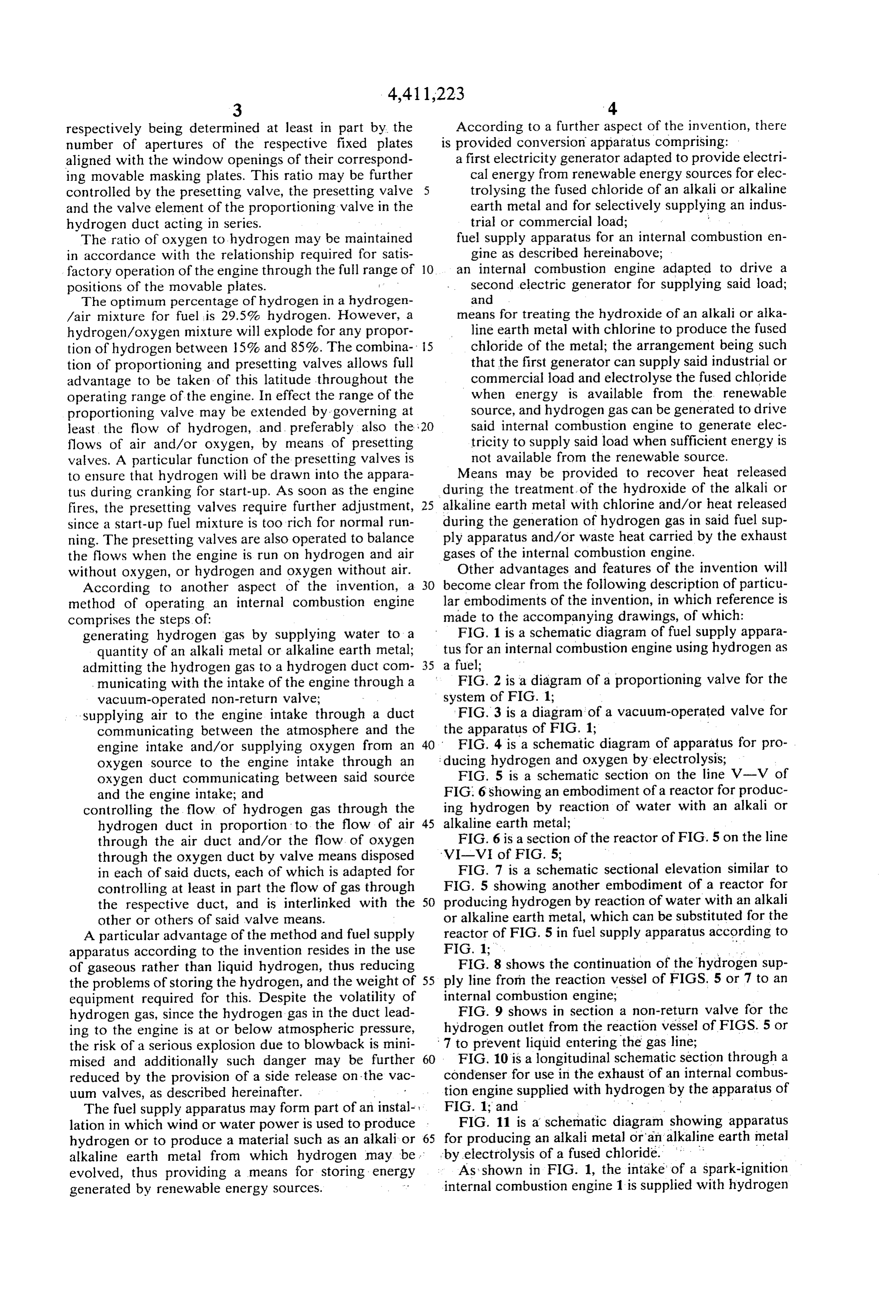
respectively being determined at least in part by the According to a further aspect of the invention, there number of apertures of the respective fixed plates is provided conversion apparatus comprising: aligned with the window openings of their correspond a first electricity generator adapted to provide electri ing movable masking plates. This ratio may be further cal energy from renewable energy sources for elec controlled by the presetting valve, the presetting valve 5 trolysing the fused chloride of an alkali or alkaline and the valve element of the proportioning valve in the earth metal and for selectively supplying an indus hydrogen duct acting in series. trial or commercial load; ; The ratio of oxygen to hydrogen may be maintained fuel supply apparatus for an internal combustion en in accordance with the relationship required for satis gine as described hereinabove; factory operation of the engine through the full range of 10. an internal combustion engine adapted to drive a positions of the movable plates. second electric generator for supplying said load; The optimum percentage of hydrogen in a hydrogen and /air mixture for fuel is 29.5% hydrogen. However, a means for treating the hydroxide of an alkali or alka hydrogen/oxygen mixture will explode for any propor line earth metal with chlorine to produce the fused tion of hydrogen between 15% and 85%. The combina 5 chloride of the metal; the arrangement being such tion of proportioning and presetting valves allows full that the first generator can supply said industrial or advantage to be taken of this latitude throughout the commercial load and electrolyse the fused chloride operating range of the engine. In effect the range of the when energy is available from the renewable proportioning valve may be extended by governing at Source, and hydrogen gas can be generated to drive least the flow of hydrogen, and preferably also the 20 said internal combustion engine to generate elec flows of air and/or oxygen, by means of presetting tricity to supply said load when sufficient energy is valves. A particular function of the presetting valves is not available from the renewable source. to ensure that hydrogen will be drawn into the appara Means may be provided to recover heat released tus during cranking for start-up. As soon as the engine during the treatment of the hydroxide of the alkali or fires, the presetting valves require further adjustment, 25 alkaline earth metal with chlorine and/or heat released since a start-up fuel mixture is too rich for normal run during the generation of hydrogen gas in said fuel sup ning. The presetting valves are also operated to balance ply apparatus and/or waste heat carried by the exhaust the flows when the engine is run on hydrogen and air gases of the internal combustion engine. without oxygen, or hydrogen and oxygen without air. Other advantages and features of the invention will According to another aspect of the invention, a 30 become clear from the following description of particu method of operating an internal combustion engine lar embodiments of the invention, in which reference is comprises the steps of: made to the accompanying drawings, of which: generating hydrogen gas by supplying water to a FIG. 1 is a schematic diagram of fuel supply appara quantity of an alkali metal or alkaline earth metal; tus for an internal combustion engine using hydrogen as admitting the hydrogen gas to a hydrogen duct com 35 a fuel;
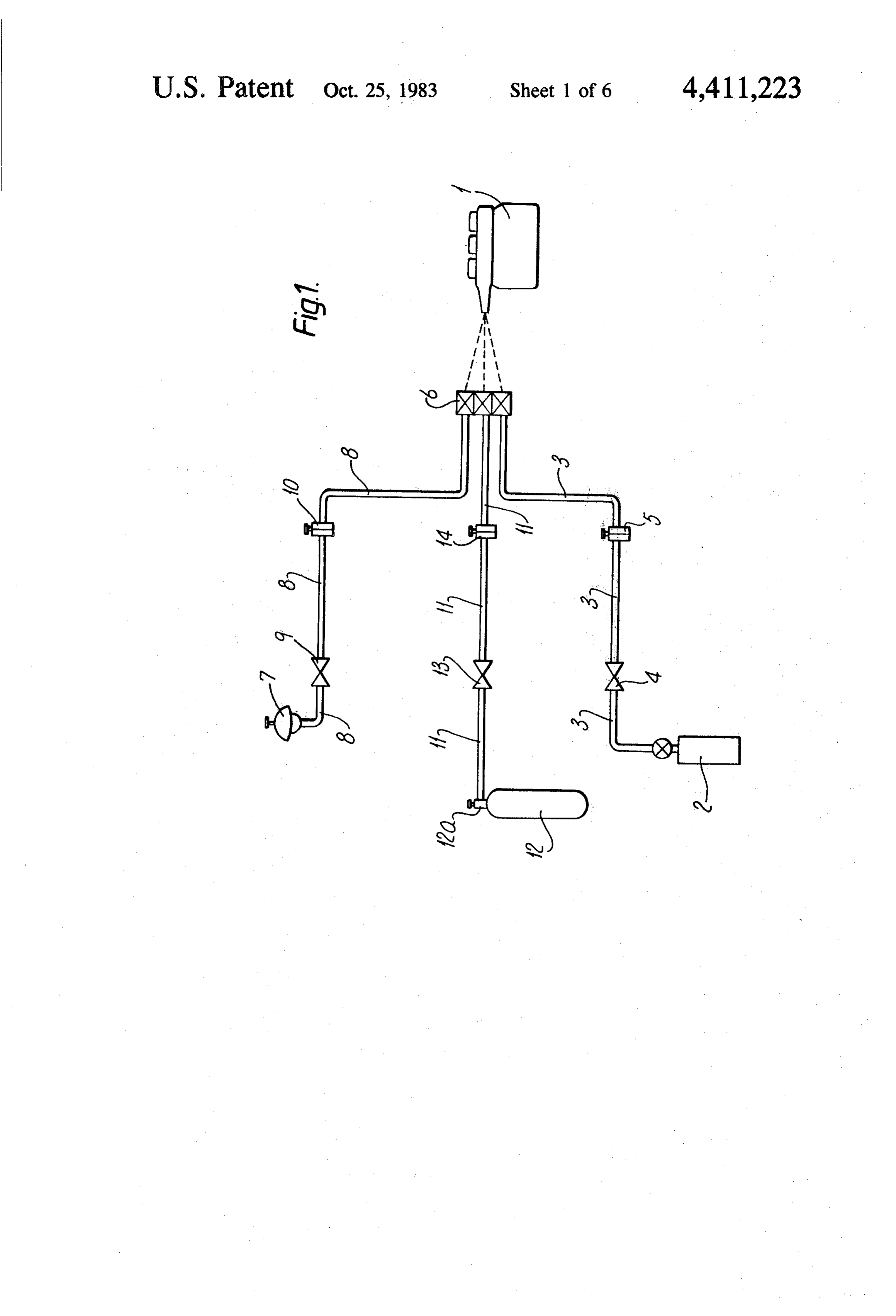
municating with the intake of the engine through a FIG. 2 is a diagram of a proportioning valve for the vacuum-operated non-return valve; system of FIG. 1;
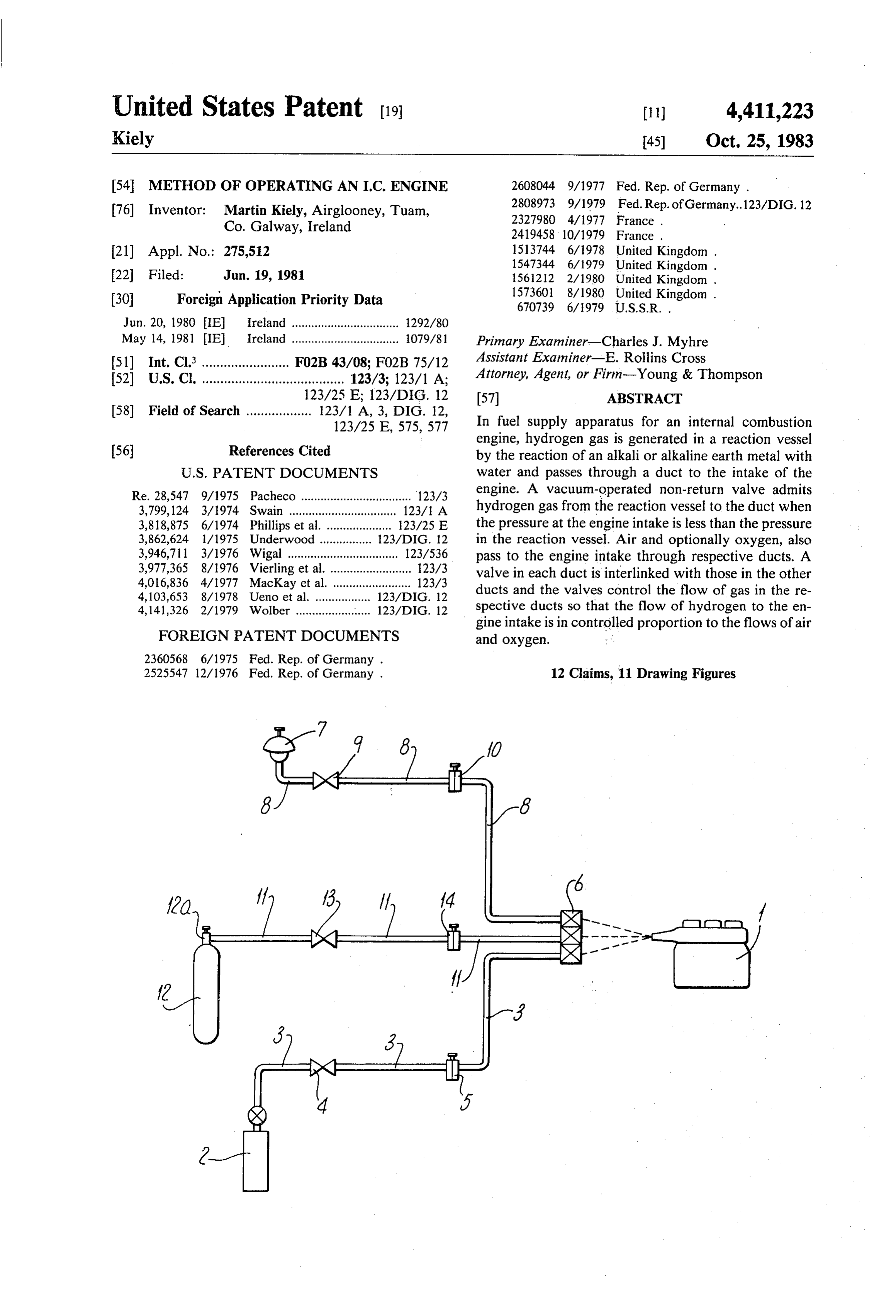
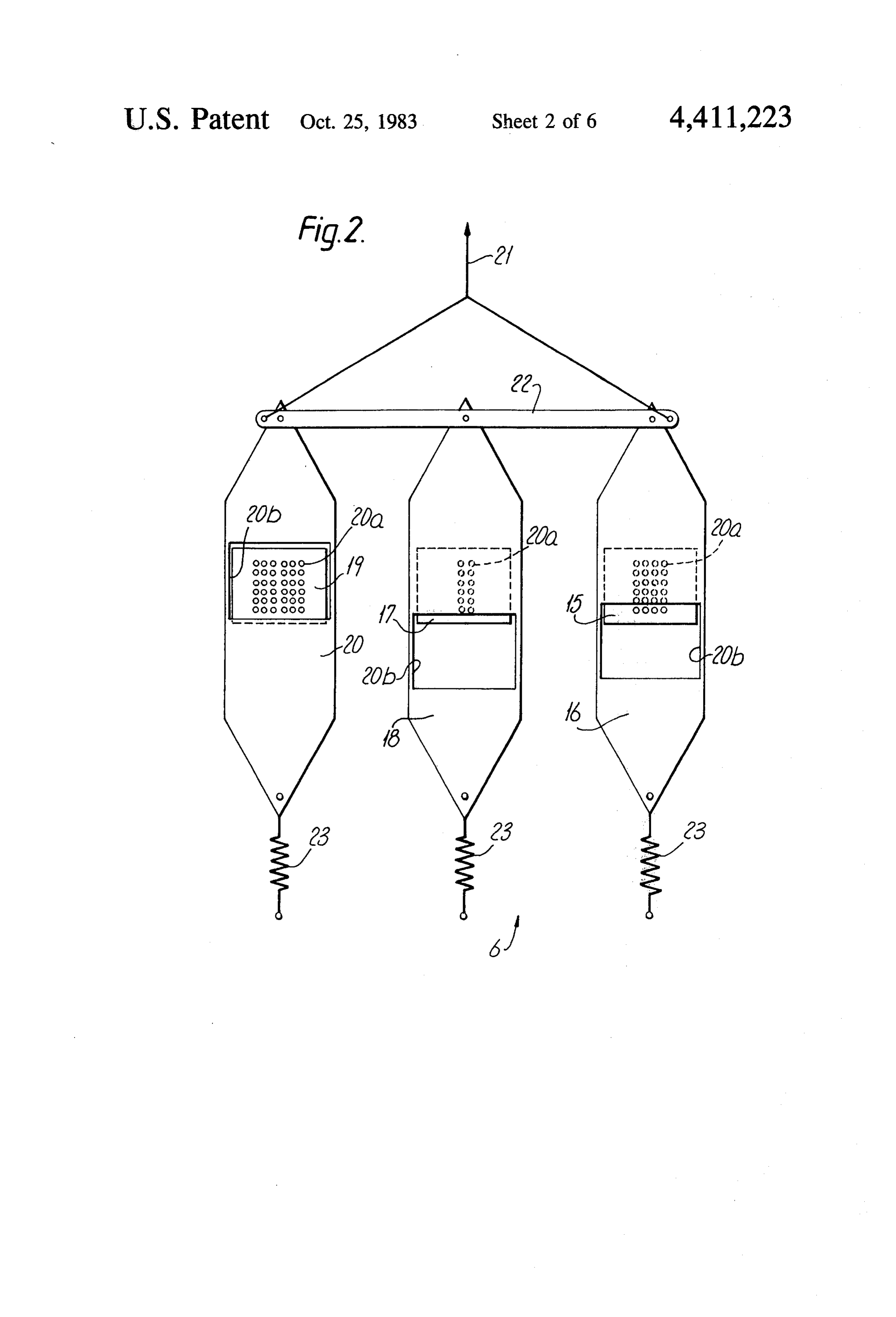
Supplying air to the engine intake through a duct IFIG. 3 is a diagram of a vacuum-operated valve for communicating between the atmosphere and the the apparatus of FIG. 1;
engine intake and/or supplying oxygen from an 40. FIG. 4 is a schematic diagram of apparatus for pro oxygen source to the engine intake through an ducing hydrogen and oxygen by electrolysis;
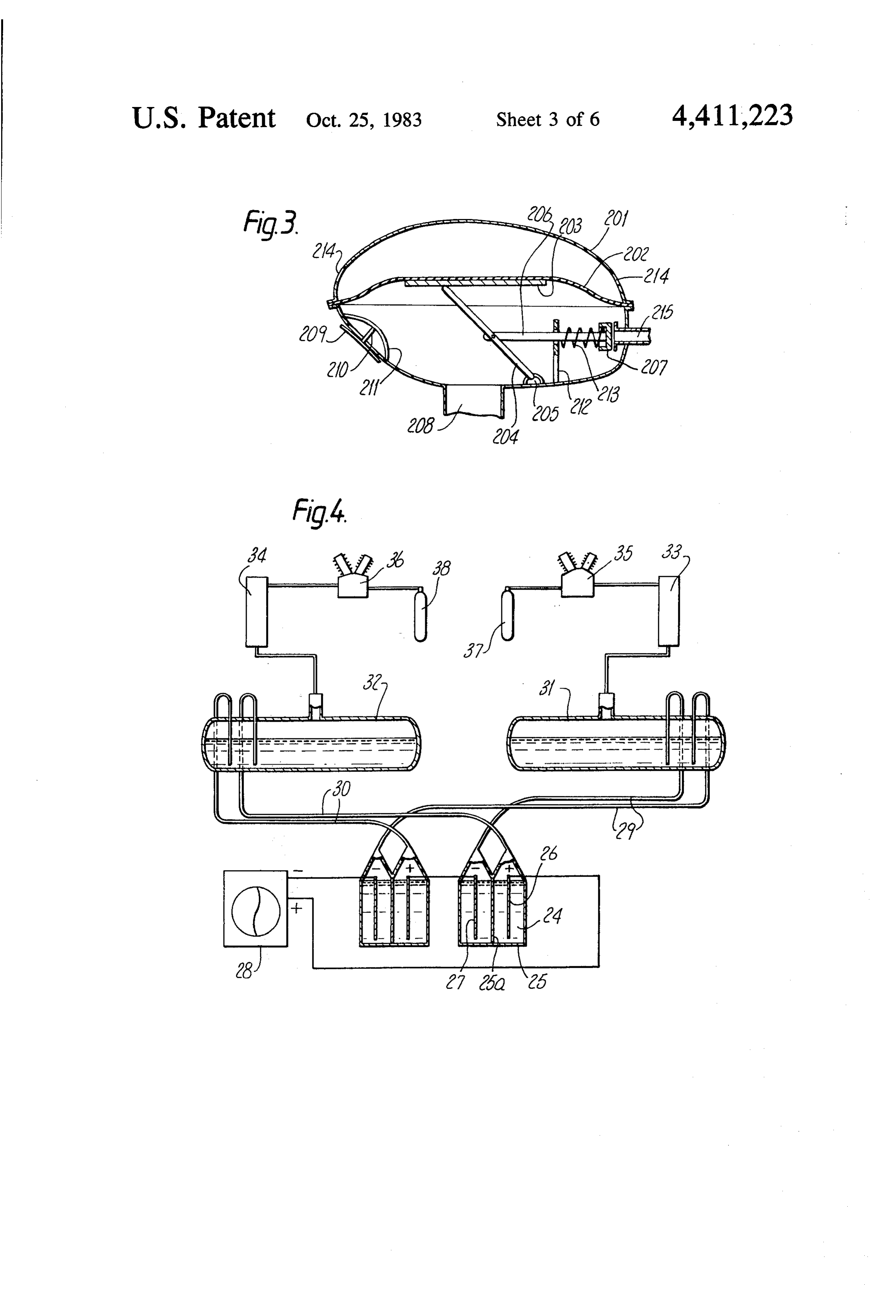
oxygen duct communicating between said source FIG. 5 is a schematic section on the line V-V of and the engine intake; and FIG. 6 showing an embodiment of a reactor for produc controlling the flow of hydrogen gas through the ing hydrogen by reaction of water with an alkali or hydrogen duct in proportion to the flow of air 45 alkaline earth metal;
through the air duct and/or the flow of oxygen FIG. 6 is a section of the reactor of FIG. 5 on the line through the oxygen duct by valve means disposed - VI-VI of FIG. 5;
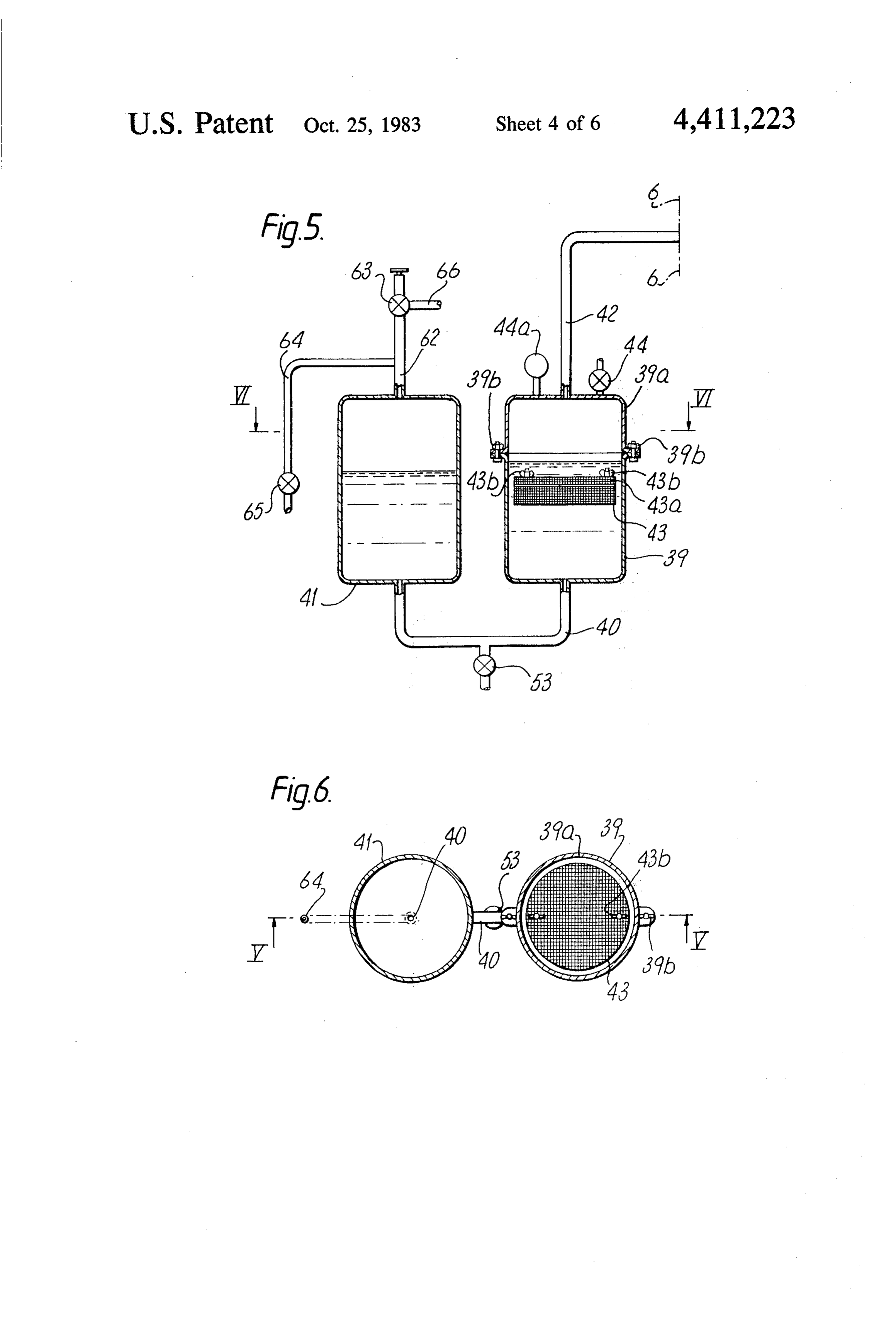
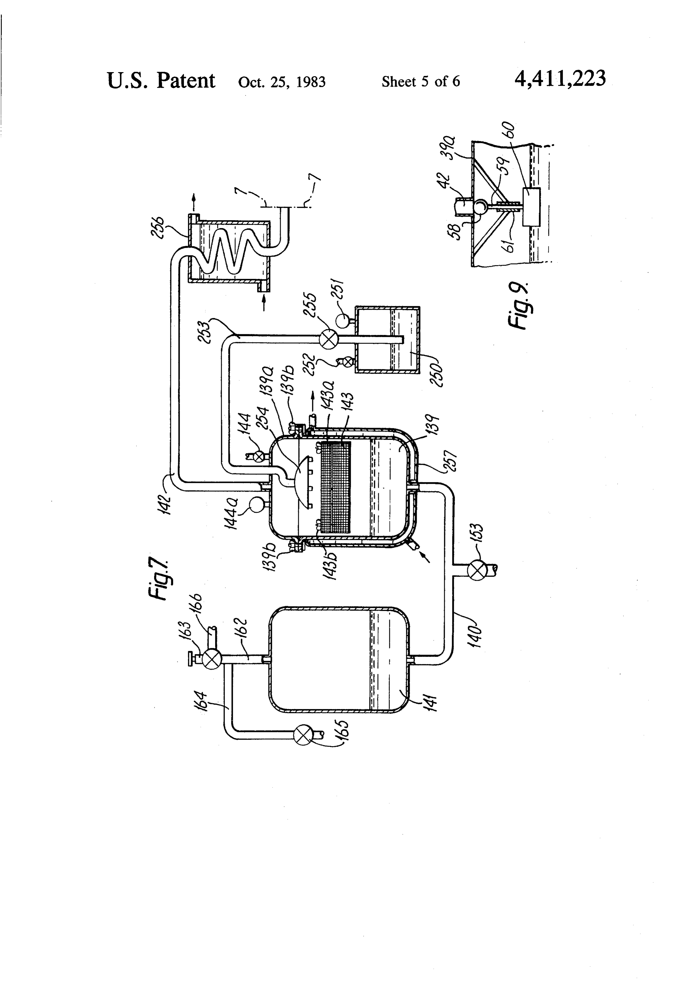
in each of said ducts, each of which is adapted for FIG. 7 is a schematic sectional elevation similar to controlling at least in part the flow of gas through FIG. 5 showing another embodiment of a reactor for the respective duct, and is interlinked with the 50 producing hydrogen by reaction of water with an alkali other or others of said valve means. or alkaline earth metal, which can be substituted for the A particular advantage of the method and fuel supply reactor of FIG. 5 in fuel supply apparatus according to apparatus according to the invention resides in the use FIG. 1;
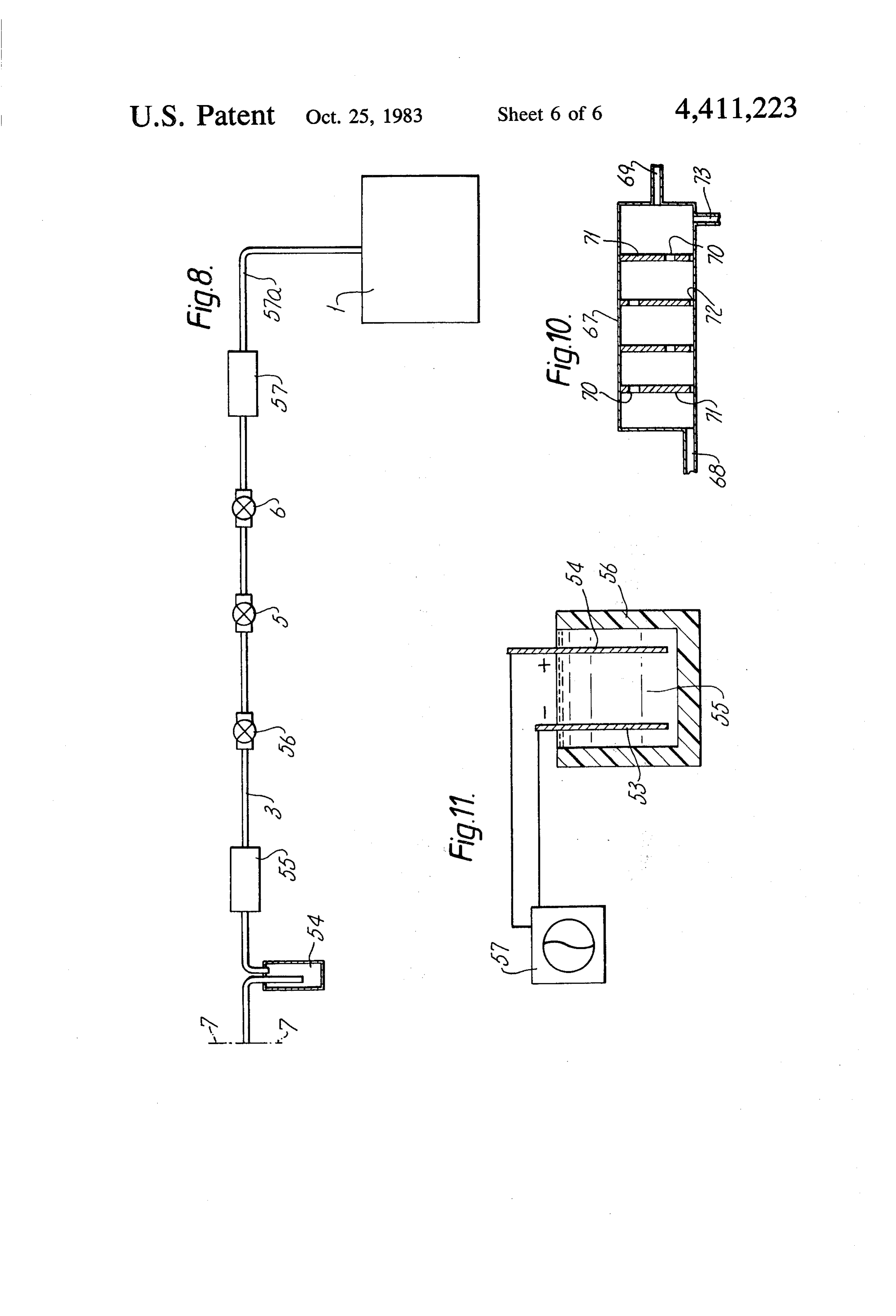
of gaseous rather than liquid hydrogen, thus reducing FIG. 8 shows the continuation of the hydrogen sup the problems of storing the hydrogen, and the weight of 55 ply line from the reaction vessel of FIGS. 5 or 7 to an equipment required for this. Despite the volatility of internal combustion engine;
hydrogen gas, since the hydrogen gas in the duct lead FIG. 9 shows in section a non-return valve for the ing to the engine is at or below atmospheric pressure, hydrogen outlet from the reaction vessel of FIGS. 5 or the risk of a serious explosion due to blowback is mini 7 to prevent liquid entering the gas line; mised and additionally such danger may be further 60 FIG. 10 is a longitudinal schematic section through a reduced by the provision of a side release on the vac condenser for use in the exhaust of an internal combus uum valves, as described hereinafter. tion engine supplied with hydrogen by the apparatus of The fuel supply apparatus may form part of an instal FIG. 1; and - lation in which wind or water power is used to produce FIG. 11 is a schematic diagram showing apparatus hydrogen or to produce a material such as an alkali or 65 for producing an alkali metal or an alkaline earth metal alkaline earth metal from which hydrogen may be . by electrolysis of a fused chloride.
evolved, thus providing a means for storing energ As shown in FIG. 1, the intake of a spark-ignition generated by renewable energy sources. internal combustion engine 1 is supplied with hydrogen
Page 10
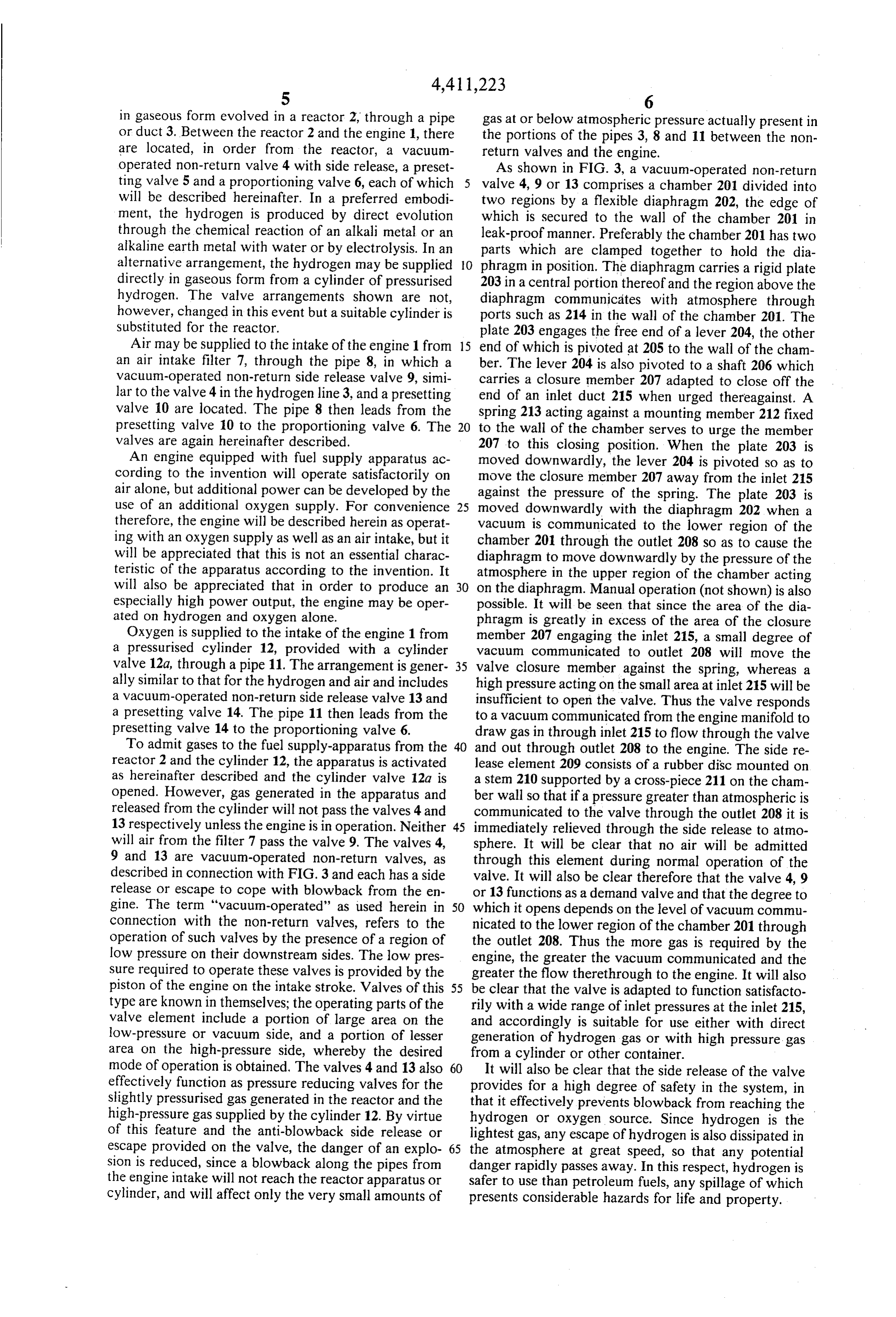
in gaseous form evolved in a reactor 2, through a pipe gas at or below atmospheric pressure actually present in or duct 3. Between the reactor 2 and the engine 1, there the portions of the pipes 3, 8 and 11 between the non are located, in order from the reactor, a vacuum return valves and the engine. operated non-return valve 4 with side release, a preset As shown in FIG. 3, a vacuum-operated non-return ting valve 5 and a proportioning valve 6, each of which valve 4, 9 or 13 comprises a chamber 201 divided into will be described hereinafter. In a preferred embodi two regions by a flexible diaphragm 202, the edge of ment, the hydrogen is produced by direct evolution which is secured to the wall of the chamber 201 in through the chemical reaction of an alkali metal or an leak-proof manner. Preferably the chamber 201 has two alkaline earth metal with water or by electrolysis. In an parts which are clamped together to hold the dia alternative arrangement, the hydrogen may be supplied O phragm in position. The diaphragm carries a rigid plate directly in gaseous form from a cylinder of pressurised 203 in a central portion thereof and the region above the hydrogen. The valve arrangements shown are not, diaphragm communicates with atmosphere through however, changed in this event but a suitable cylinder is ports such as 214 in the wall of the chamber 201. The Substituted for the reactor. plate 203 engages the free end of a lever 204, the other Air may be supplied to the intake of the engine 1 from 15 end of which is pivoted at 205 to the wall of the cham an air intake filter 7, through the pipe 8, in which a ber. The lever 204 is also pivoted to a shaft 206 which vacuum-operated non-return side release valve 9, simi carries a closure member 207 adapted to close off the lar to the valve 4 in the hydrogen line 3, and a presetting end of an inlet duct 215 when urged thereagainst. A valve 10 are located. The pipe 8 then leads from the spring 213 acting against a mounting member 212 fixed presetting valve 10 to the proportioning valve 6. The 20 to the wall of the chamber serves to urge the member valves are again hereinafter described. 207 to this closing position. When the plate 203 is An engine equipped with fuel supply apparatus ac moved downwardly, the lever 204 is pivoted so as to cording to the invention will operate satisfactorily on move the closure member 207 away from the inlet 215 air alone, but additional power can be developed by the against the pressure of the spring. The plate 203 is use of an additional oxygen supply. For convenience 25 moved downwardly with the diaphragm 202 when a therefore, the engine will be described herein as operat vacuum is communicated to the lower region of the ing with an oxygen supply as well as an air intake, but it chamber 201 through the outlet 208 so as to cause the will be appreciated that this is not an essential charac diaphragm to move downwardly by the pressure of the teristic of the apparatus according to the invention. It atmosphere in the upper region of the chamber acting will also be appreciated that in order to produce an 30 on the diaphragm. Manual operation (not shown) is also especially high power output, the engine may be oper possible. It will be seen that since the area of the dia ated on hydrogen and oxygen alone. phragm is greatly in excess of the area of the closure Oxygen is supplied to the intake of the engine 1 from member 207 engaging the inlet 215, a small degree of a pressurised cylinder 12, provided with a cylinder vacuum communicated to outlet 208 will move the valve 12a, through a pipe 11. The arrangement is gener 35 valve closure member against the spring, whereas a ally similar to that for the hydrogen and air and includes high pressure acting on the small area at inlet 215 will be a vacuum-operated non-return side release valve 13 and insufficient to open the valve. Thus the valve responds a presetting valve 14. The pipe 11 then leads from the to a vacuum communicated from the engine manifold to presetting valve 14 to the proportioning valve 6. draw gas in through inlet 215 to flow through the valve To admit gases to the fuel supply-apparatus from the 40 and out through outlet 208 to the engine. The side re reactor 2 and the cylinder 12, the apparatus is activated lease element 209 consists of a rubber disc mounted on as hereinafter described and the cylinder valve 12a is a stem 210 supported by a cross-piece 211 on the cham opened. However, gas generated in the apparatus and ber wall so that if a pressure greater than atmospheric is released from the cylinder will not pass the valves 4 and communicated to the valve through the outlet 208 it is 13 respectively unless the engine is in operation. Neither 45 immediately relieved through the side release to atmo will air from the filter 7 pass the valve 9. The valves 4, sphere. It will be clear that no air will be admitted 9 and 13 are vacuum-operated non-return valves, as through this element during normal operation of the described in connection with FIG. 3 and each has a side valve. It will also be clear therefore that the valve 4, 9 release or escape to cope with blowback from the en or 13 functions as a demand valve and that the degree to gine. The term "vacuum-operated' as used herein in 50 which it opens depends on the level of vacuum commu connection with the non-return valves, refers to the nicated to the lower region of the chamber 201 through operation of such valves by the presence of a region of the outlet 208. Thus the more gas is required by the low pressure on their downstream sides. The low pres engine, the greater the vacuum communicated and the sure required to operate these valves is provided by the greater the flow therethrough to the engine. It will also piston of the engine on the intake stroke. Valves of this 55 be clear that the valve is adapted to function satisfacto type are known in themselves; the operating parts of the rily with a wide range of inlet pressures at the inlet 215, valve element include a portion of large area on the and accordingly is suitable for use either with direct low-pressure or vacuum side, and a portion of lesser generation of hydrogen gas or with high pressure gas area on the high-pressure side, whereby the desired from a cylinder or other container.
mode of operation is obtained. The valves 4 and 13 also 60 It will also be clear that the side release of the valve effectively function as pressure reducing valves for the provides for a high degree of safety in the system, in slightly pressurised gas generated in the reactor and the that it effectively prevents blowback from reaching the high-pressure gas supplied by the cylinder 12. By virtue hydrogen or oxygen source. Since hydrogen is the of this feature and the anti-blowback side release or lightest gas, any escape of hydrogen is also dissipated in escape provided on the valve, the danger of an explo 65 the atmosphere at great speed, so that any potential sion is reduced, since a blowback along the pipes from danger rapidly passes away. In this respect, hydrogen is the engine intake will not reach the reactor apparatus or safer to use than petroleum fuels, any spillage of which cylinder, and will affect only the very small amounts of presents considerable hazards for life and property.
Page 11
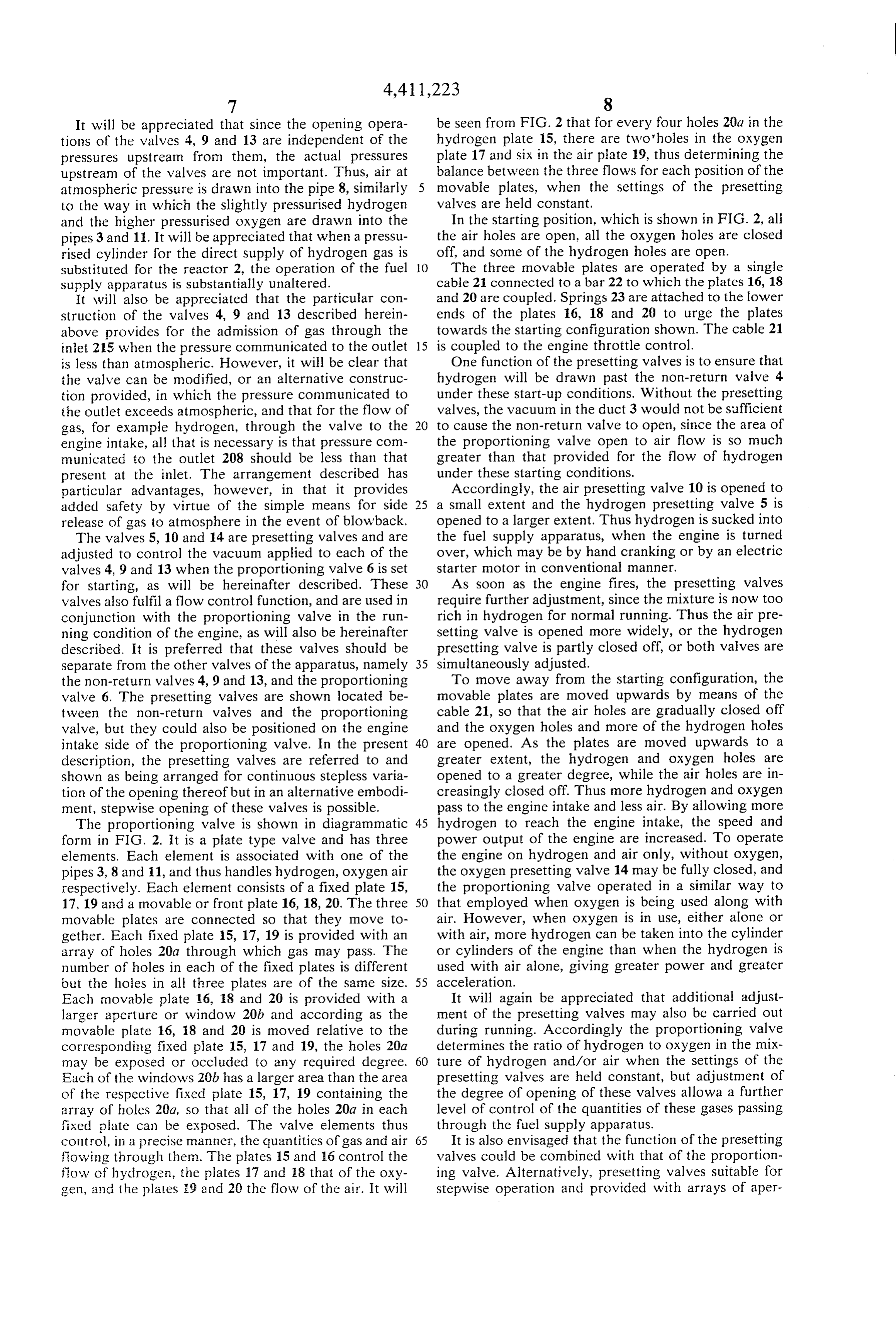
It will be appreciated that since the opening opera be seen from FIG. 2 that for every four holes 20a in the tions of the valves 4, 9 and 13 are independent of the hydrogen plate 15, there are two holes in the oxygen pressures upstream from them, the actual pressures plate 17 and six in the air plate 19, thus determining the upstream of the valves are not important. Thus, air at balance between the three flows for each position of the atmospheric pressure is drawn into the pipe 8, similarly movable plates, when the settings of the presetting to the way in which the slightly pressurised hydrogen valves are held constant, and the higher pressurised oxygen are drawn into the In the starting position, which is shown in FIG. 2, all pipes 3 and 11. It will be appreciated that when a pressu the air holes are open, all the oxygen holes are closed rised cylinder for the direct supply of hydrogen gas is off, and some of the hydrogen holes are open. substituted for the reactor 2, the operation of the fuel O The three movable plates are operated by a single supply apparatus is substantially unaltered. cable 21 connected to a bar 22 to which the plates 16, 18 It will also be appreciated that the particular con and 20 are coupled. Springs 23 are attached to the lower struction of the valves 4, 9 and 13 described herein ends of the plates 16, 18 and 20 to urge the plates above provides for the admission of gas through the towards the starting configuration shown. The cable 21 inlet 215 when the pressure communicated to the outlet 15 is coupled to the engine throttle control. is less than atmospheric. However, it will be clear that One function of the presetting valves is to ensure that the valve can be modified, or an alternative construc hydrogen will be drawn past the non-return valve 4 tion provided, in which the pressure communicated to under these start-up conditions. Without the presetting the outlet exceeds atmospheric, and that for the flow of valves, the vacuum in the duct 3 would not be sufficient gas, for example hydrogen, through the valve to the to cause the non-return valve to open, since the area of engine intake, all that is necessary is that pressure com the proportioning valve open to air flow is so much municated to the outlet 208 should be less than that greater than that provided for the flow of hydrogen present at the inlet. The arrangement described has under these starting conditions.
particular advantages, however, in that it provides Accordingly, the air presetting valve 10 is opened to added safety by virtue of the simple means for side 25 a small extent and the hydrogen presetting valve 5 is release of gas to atmosphere in the event of blowback. opened to a larger extent. Thus hydrogen is sucked into The valves 5, 10 and 14 are presetting valves and are the fuel supply apparatus, when the engine is turned adjusted to control the vacuum applied to each of the over, which may be by hand cranking or by an electric valves 4, 9 and 13 when the proportioning valve 6 is set starter motor in conventional manner. for starting, as will be hereinafter described. These 30 As soon as the engine fires, the presetting valves valves also fulfil a flow control function, and are used in require further adjustment, since the mixture is now too conjunction with the proportioning valve in the run rich in hydrogen for normal running. Thus the air pre ning condition of the engine, as will also be hereinafter setting valve is opened more widely, or the hydrogen described. It is preferred that these valves should be presetting valve is partly closed off, or both valves are separate from the other valves of the apparatus, namely 35 simultaneously adjusted.
the non-return valves 4, 9 and 13, and the proportioning To move away from the starting configuration, the valve 6. The presetting valves are shown located be movable plates are moved upwards by means of the tween the non-return valves and the proportioning cable 21, so that the air holes are gradually closed off valve, but they could also be positioned on the engine and the oxygen holes and more of the hydrogen holes intake side of the proportioning valve. In the present 40 are opened. As the plates are moved upwards to a description, the presetting valves are referred to and greater extent, the hydrogen and oxygen holes are shown as being arranged for continuous stepless varia opened to a greater degree, while the air holes are in tion of the opening thereof but in an alternative embodi creasingly closed off. Thus more hydrogen and oxygen ment, stepwise opening of these valves is possible. pass to the engine intake and less air. By allowing more The proportioning valve is shown in diagrammatic 45 hydrogen to reach the engine intake, the speed and form in FIG. 2. It is a plate type valve and has three power output of the engine are increased. To operate elements. Each element is associated with one of the the engine on hydrogen and air only, without oxygen, pipes 3, 8 and 11, and thus handles hydrogen, oxygen air the oxygen presetting valve 14 may be fully closed, and respectively. Each element consists of a fixed plate 15, the proportioning valve operated in a similar way to 17, 19 and a movable or front plate 16, 18, 20. The three 50 that employed when oxygen is being used along with movable plates are connected so that they move to air. However, when oxygen is in use, either alone or gether. Each fixed plate 15, 17, 19 is provided with an with air, more hydrogen can be taken into the cylinder array of holes 20a through which gas may pass. The or cylinders of the engine than when the hydrogen is number of holes in each of the fixed plates is different used with air alone, giving greater power and greater but the holes in all three plates are of the same size. 55 acceleration.
Each movable plate 16, 18 and 20 is provided with a It will again be appreciated that additional adjust larger aperture or window 20b and according as the ment of the presetting valves may also be carried out movable plate 16, 18 and 20 is moved relative to the during running. Accordingly the proportioning valve corresponding fixed plate 15, 17 and 19, the holes 20a determines the ratio of hydrogen to oxygen in the mix may be exposed or occluded to any required degree. 60 ture of hydrogen and/or air when the settings of the Each of the windows 20b has a larger area than the area presetting valves are held constant, but adjustment of of the respective fixed plate 15, 17, 19 containing the the degree of opening of these valves allowa a further array of holes 20a, so that all of the holes 20a in each level of control of the quantities of these gases passing fixed plate can be exposed. The valve elements thus through the fuel supply apparatus.
control, in a precise manner, the quantities of gas and air 65 It is also envisaged that the function of the presetting flowing through them. The plates 15 and 16 control the valves could be combined with that of the proportion flow of hydrogen, the plates 17 and 18 that of the oxy ing valve. Alternatively, presetting valves suitable for gen, and the plates 9 and 20 the flow of the air. It will stepwise operation and provided with arrays of aper
Page 12
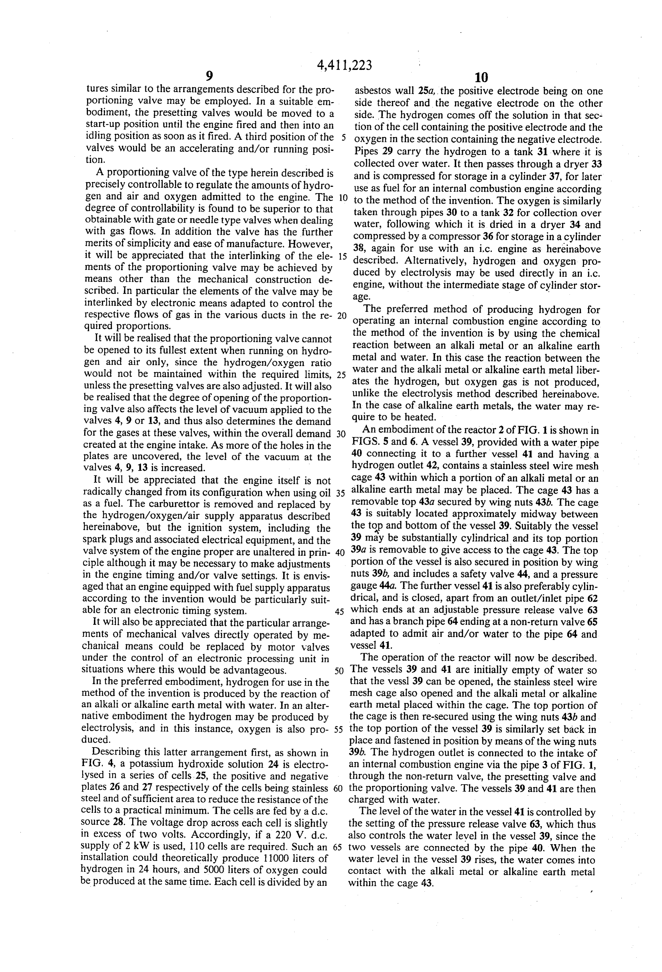
tures similar to the arrangements described for the pro asbestos wall 25a, the positive electrode being on one portioning valve may be employed. In a suitable en side thereof and the negative electrode on the other bodiment, the presetting valves would be moved to a side. The hydrogen comes off the solution in that sec start-up position until the engine fired and then into an tion of the cell containing the positive electrode and the idling position as soon as it fired. A third position of the 5 oxygen in the section containing the negative electrode. valves would be an accelerating and/or running posi Pipes 29 carry the hydrogen to a tank 31 where it is tion. collected over water. It then passes through a dryer 33 A proportioning valve of the type herein described is and is compressed for storage in a cylinder 37, for later precisely controllable to regulate the amounts of hydro use as fuel for an internal combustion engine according gen and air and oxygen admitted to the engine. The 10 the method of the invention. The oxygen is similarly degree of controllability is found to be superior to that to obtainable with gate or needle type valves when dealing taken through pipes 30 to a tank 32 for collection over water, following which it is dried in a dryer 34 and with gas flows. In addition the valve has the further compressed by a compressor 36 for storage in a cylinder merits of simplicity and ease of manufacture. However, 38, again for use with an ic. engine as hereinabove it will be appreciated that the interlinking of the ele 15 described. Alternatively, hydrogen and oxygen pro ments of the proportioning valve may be achieved by duced by electrolysis may be used directly in an ic. means other than the mechanical construction de scribed. In particular the elements of the valve may be engine, without the intermediate stage of cylinder stor interlinked by electronic means adapted to control the age.The preferred method of producing hydrogen for respective flows of gas in the various ducts in the re 20 operating an internal combustion engine according to quired proportions.
It will be realised that the proportioning valve cannot the method of the invention is by using the chemical reaction between an alkali metal or an alkaline earth be opened to its fullest extent when running on hydro metal and water. In this case the reaction between the gen and air only, since the hydrogen/oxygen ratio would not be maintained within the required limits, 25 water ates and the alkali metal or alkaline earth metal liber the hydrogen, but oxygen gas is not produced, unless the presetting valves are also adjusted. It will also be realised that the degree of opening of the proportion unlike the electrolysis method described hereinabove. In the case of alkaline earth metals, the water may re ing valve also affects the level of vacuum applied to the quire valves 4, 9 or 13, and thus also determines the demand to be heated.
for the gases at these valves, within the overall demand 30 An embodiment of the reactor 2 of FIG. 1 is shown in created at the engine intake. As more of the holes in the FIGS. 5 and 6. A vessel 39, provided with a water pipe plates are uncovered, the level of the vacuum at the 40 connecting it to a further vessel 41 and having a valves 4, 9, 13 is increased. hydrogen outlet 42, contains a stainless steel wire mesh It will be appreciated that the engine itself is not cage 43 within which a portion of an alkali metal or an radically changed from its configuration when using oil 35 alkaline earth metal may be placed. The cage 43 has a as a fuel. The carburettor is removed and replaced by removable top 43a secured by wing nuts 43b. The cage the hydrogen/oxygen/air supply apparatus described 43 is suitably located approximately midway between hereinabove, but the ignition system, including the the top a. and bottom of the vessel 39. Suitably the vessel
Spark plugs and associated electrical equipment, and the 39 may be substantially cylindrical and its top portion valve system of the engine proper are unaltered in prin 40 39a is removable to give access to the cage 43. The top ciple although it may be necessary to make adjustments portion of the vessel is also secured in position by wing in the engine timing and/or valve settings. It is envis nuts 39b, and includes a safety valve 44, and a pressure aged that an engine equipped with fuel supply apparatus gauge 44a. The further vessel 41 is also preferably cylin according to the invention would be particularly suit drical, and is closed, apart from an outlet/inlet pipe 62 able for an electronic timing system. 45 which ends at an adjustable pressure release valve 63 It will also be appreciated that the particular arrange and has a branch pipe 64 ending at a non-return valve 65 ments of mechanical valves directly operated by me adapted to admit air and/or water to the pipe 64 and chanical means could be replaced by motor valves vessel 41.
under the control of an electronic processing unit in The operation of the reactor will now be described. situations where this would be advantageous. 50 The vessels 39 and 41 are initially empty of water so In the preferred embodiment, hydrogen for use in the that the vessl 39 can be opened, the stainless steel wire method of the invention is produced by the reaction of mesh cage also opened and the alkali metal or alkaline an alkali or alkaline earth metal with water. In an alter earth metal placed within the cage. The top portion of native embodiment the hydrogen may be produced by the cage is then re-secured using the wing nuts 43b and electrolysis, and in this instance, oxygen is also pro 55 the top portion of the vessel 39 is similarly set back in duced. place and fastened in position by means of the wing nuts Describing this latter arrangement first, as shown in 39b. The hydrogen outlet is connected to the intake of FIG, 4, a potassium hydroxide solution 24 is electro an internal combustion engine via the pipe 3 of FIG. 1, lysed in a series of cells. 25, the positive and negative through the non-return valve, the presetting valve and plates 26 and 27 respectively of the cells being stainless 60 the proportioning valve. The vessels 39 and 41 are then Steel and of sufficient area to reduce the resistance of the charged with water. - cells to a practical minimum. The cells are fed by a d.c. The level of the water in the vessel 41 is controlled by Source 28. The voltage drop across each cell is slightly the setting of the pressure release valve 63, which thus in excess of two volts. Accordingly, if a 220 V. d.c. also controls the water level in the vessel 39, since the supply of 2 kW is used, 110 cells are required. Such an 65 two vessels are connected by the pipe 40. When the installation could theoretically produce 1 1000 liters of water level in the vessel 39 rises, the water comes into hydrogen in 24 hours, and 5000 liters of oxygen could contact with the alkali metal or alkaline earth metal be produced at the same time. Each cell is divided by an within the cage 43. v
Page 13
The result of this is a very rapid evolution of hydro sure vessel 250, on to the alkali or alkaline earth metal gen. It is necessary that the production rate of the hy contained in the cage 143. A valve 255 in the pipeline drogen exceeds the rate of its usage by the engine, and 253 controls the flow of water through the pipe. When in order to control the rate of evolution of the hydro the valve 255 is opened, water flows from the vessel gen, the reactor works as follows. As hydrogen is pro- 5 250, since the vessel is under pressure, and the end of duced, gas pressure builds up in the vessel 39 and pushes the pipe 253 within the vessel is below the water level. down the level of the water therein. When the level The water sprays onto the metal in the cage, hydrogen drops below that of the alkali or alkaline earth metal, is generated and pressure is immediately built up in the the production of hydrogen ceases. This fall of level in vessel 139. When the gas pressure in the vessel 139 the vessel 39 is partly compensated by a rise in the water 10 becomes equal to or exceeds the water pressure at the level in the vessel 41 and partly by water being con nozzles of devices 254, the water stops flowing into the sumed in producing the hydrogen. The relative sizes of reactor vessel 139. As the engine runs, and hydrogen is the vessels 39 and 41 and the setting of the valve 63 are withdrawn from the vessel 139, the pressure in this chosen so that hydrogen production will cease at a vessel again drops, so allowing water to once more specified pressure of hydrogen in the vessel 39. As the 15 spray onto the metal and again build up gas pressure in water level in the vessel 41 rises, the air above it is the vessel 139. Thus hydrogen is produced only on compressed. If the air pressure exceeds the setting of the demand by the engine.
valve 63, the pressure is relieved by the valve. Air As shown in FIG. 7, the vessel 139 contains a body of blowing off from valve 63 may be led away through a water and is connected by pipe 140 to the vessel 141, branch pipe 66 which may exhaust to atmosphere, or 20 similar to the arrangement shown in FIG. 5. While the over a water tray or vessel. presence of water in large quantity in the vessel 139 is According as the engine uses the hydrogen produced not essential with the spray arrangement of FIG. 7, a in the vessel 39 and the hydrogen is consumed, the certain amount is required in order to dilute the concen pressure in the vessel 39 falls. With the drop in pressure, trated hydroxide resulting from the reaction vessel of the water level can rise again in the vessel 39, as ex- 25 metal and the water. The operating pressure of the plained below, so that the water again comes into vessel 139 is low, and may be of the order of five to ten contact with the metal in the cage, and more hydrogen psi. Actual operating pressures will depend on the de is given off. sign of the reactor vessel and the hydrogen demand. The non-return valve 65 at the end of the branch pipe This embodiment of the reactor facilitates control of the 64 allows the water level in the vessel 39 to rise, by 30 rate of evolution of the hydrogen, which is especially admitting air to the vessel 41 above the level of the advantageous in situations where demand varies rap water in that vessel, when the pressure above the water idly.
in the vessel falls below atmospheric. The evolution of the hydrogen in the reactor is ac In order to “top up' the water in the vessels 39 and companied by the generation of a considerable amount 41, or to reintroduce condensed water from the engine 35 of heat. Thus it is advantageous to include a condenser exhaust in a closed system, the non-return valve may be cooled by water in the line 142 leading from the vessel arranged to be below, at least some of the time, the 139. As will be described below, the condenser is fol surface of water or condensate in a suitable tray or lowed by a water trap. The condenser includes a coil vessel, so that the water or condensate is sucked into the through which the gas passes and a water jacket and is vessel 41 by a negative pressure therewithin. To guard 40 of known design which will not be described further. against loss of water when the system is closed, the Advantageously, a water jacket 257 is also provided on branch pipe 66 may also end above the tray so that any the vessel 139. As also described hereinafter, the ex water expelled from the vessel 41 during the evolution haust line from the engine may also include a water of hydrogen in vessel 39 can be returned to be taken into cooler, so that the heat from all of these jackets and the vessel again when there is a negative pressure within 45 coolers may be collected in a single hot water circuit. In it. this circumstance the water from the condenser 256 is An alternative embodiment of the reactor 2 is shown first directed to the exhaust gas cooler and thereafter to in FIG. 7. The arrangement is in many respects similar the cooling jacket on the reactor vessel 139. In the case to that of FIGS. 5 and 6 but the hydrogen is evolved by of a stationary engine, the heat may be used for space spraying water onto the alkali or alkaline earth metal 50 heating or for supplying hot water. With mobile or contained in the cage, rather than by immersing the vehicle engines, the heat can be liberated in the form of metal in water, as is the case in the previously described steam, and may possibly be used to drive a small tur embodiment. Those items in FIG. 7 which are substan bine.
tially identical with items in FIGS. 5 and 6 are distin The alkali metal or alkaline earth metal may, in addi guished by the use of the same identifying numerals, 55 tion to the cage arrangements described above or in part with the addition of one hundred in each case. replacement of them, be fully encased in a water soluble As shown in FIG. 7, a pressure vessel 250 contains material or encased in a material insoluble in water but water and is charged to an outlet pressure determined having holes in it to admit water to the metal encased. by the pressure which the spray is required to overcome By this means an additional or alternative control may in the vessel 139. The vessel 250 is provided with a 60 be imposed on the rate at which the hydrogen gas is pressure gauge 251 and an inlet 252, through which it evolved.
may be charged with water and pressurized. Instead of The hydrogen evolved may be stored, if desired, the pressure vessel 250, a pump may be used, which is instead of being supplied direct to an internal combus adjusted and controlled to feed water at a predeter tion engine.
mined pressure to the vessel 139. A pipe 253 connects 65 FIG. 8 shows a modified version of the hydrogen line the pressure vessel 250 to the vessel 139, where it termi 3 of FIG. 1 continuing from the line 6-6 in FIG. 5 or nates in a nozzle device 254, adapted to spray water the line 7-7 in FIG. 6. In this case the line includes received through the pipe under pressure from the pres various elements not included in FIG. 1, mainly di
Page 14
rected towards drying of the hydrogen en route to the with the holes 70 in its upper part being followed by one engine 1. From the outlet 42 of vessel 39 in FIG. 5, or with the holes in its lower part, so as to promote con from the condenser 256 of FIG. 7, the hydrogen passes densation of water vapour in the exhaust. Each baffle 71 through a trap 54, intended to remove water from it, also has an opening 72 at its bottom part to allow con and then through a dryer 55, which contains a quantity densed water vapour to flow to a condensate outlet 73. of dessicating material. Valve 56 is a vacuum operated It is a further advantage of the reactor illustrated in side release safety valve and is followed by the preset FIGS. 5 or 7 that the alkali and alkaline earth metal used ting valve 5 and the proportioning valve 6 as shown in in the evolution of the hydrogen may be regenerated for FIG. 1. FIG. 8 only shows the hydrogen line 3 to the further use. The end result of the operations described proportioning valve 6 but it will be understood that O in relation to FIGS. 5 or 7 is a solution of the hydroxide there are also oxygen and air feeds to valve 6 and that of the alkali or alkaline earth metal, which may go as the line 57a leading from the proportioning valve to the high as 85% in strength before its replacement becomes engine 1 carries not only hydrogen but also air and/or necessary. The solution can be treated with chlorine gas oxygen. 57 represents a further dryer also containing a to produce the chloride of the alkali or alkaline earth quantity of desiccant for further drying the combined 15 metal from which the metal itself may be recovered. It gas flow between the proportioning valve and the en is a further advantage that heat evolved during the gine. With high compression ratio engines, it may be treatment of the hydroxide may be used at other stages preferable to omit the dryers 55 and 57, as very dry gas of the process, thereby improving the overall efficiency. can result in the emission of the pollutant nitric oxide. FIG. 11 shows a system for producing an alkali metal Thus the presence of a quantity of moisture may be 20 or alkaline earth metal, by electrolysis of the fused chlo preferable. ride of the metal required, with small quantities of an FIG. 9 shows one form of non-return valve for pre other alkali or alkaline earth metal chloride added in venting carry-over of water from the vessel 39 of FIG. order to reduce the melting point.
5 into the line 3 which can occur in operation of the A cathode 53 of iron and an anode 54 of carbon are engine in the event of a sudden surge or demand for gas. 25 used, and are placed in the fused chloride 55 to which is A ball valve element 58 is mounted on a rod 59 extend added the other alkali or alkaline earth metal chloride. ing from a float element 60 on the surface of the water The mixture is contained in a heated and insulated ves in the vessel, and is guided and restrained in vertical sel 56 and a d.c. source 57 is placed across the elec movement towards and away from the outlet 42 by trodes. The production of alkali or alkaline earth metals guides 61. Thus if the water level rises beyond a prede 30 in this way is well known.
termined amount, the ball 58 closes off the outlet 42 and Both the electrolysis method of generating hydrogen stops flow of gas until the surge has ceased. In this way and the system involving the use of an alkali or alkaline the line 3 and the valve associated with it are protected earth metal are envisaged as suitable for use in conjunc from flooding and possible damage by the water. tion with electricity generation using renewable sources It will be appreciated that FIGS. 8 and 9 represent 35 of energy, e.g. wind, small scale water generation, and only one method of embodying the features shown solar voltaic cells. A major disadvantage of renewable therein and that other equivalent means may be em energy sources is the difficulty of storing surplus en ployed within the scope of the invention. ergy, e.g. energy collected by a solar panel on a hot A further safety feature is shown in FIG. 6 in the sunny day, for use on subsequent occasions, e.g. on a form of valve 53 in the pipe 40 connecting the vessels 39 cold day. The most commonly used known method is and 41. This valve serves to drain the water from the by means of storage batteries, but this is cumbersome, reactor vessels when it is not desired to generate hydro expensive and not wholly satisfactory. The apparatus gen and it may lead to a drain compartment or vessel for and method described herein allow the conversion of the water. It also fulfills a safety function in that it can such surplus energy into hydrogen which may then be act as a dump valve to drain the reactor vessels rapidly 45 used as a fuel for known internal combustion engines, in the event of any untoward circumstance which re either immediately or on some later occasion, thus pro quires urgent cessation of the evolution of hydrogen. It viding convenient and safe storage of the energy. can thus be coupled to an emergency button or lever The surplus energy generated may be used for the available to the operator or driver. electrolysis of, for example, potassium hydroxide to A similar safety feature can be included in the reactor 50 produce hydrogen and oxygen gas directly, for immedi of FIG. 7 for rapid release of the pressure in the vessel ate use or for storage under pressure or the energy may 250. be used for electrolysis of fused chlorides to produce In another feature of the fuel supply apparatus, water alkali or alkaline earth metals for later use to produce in the exhaust from the engine can be condensed and the hydrogen for direct use in an engine. Hydrogen pro condensed water directed back to the vessel 41 or 141 55 duced may be stored in cylinders as described or may be so that the water system of the reactor is closed, and the stored in other means, e.g. under a bell, from which it water in it is continuously recycled. The condensate can may be drawn to run an i.c. engine for generating elec be pumped back to the vessel 41 or 141 or can flow tricity when weather conditions prevent energy being under gravity if the condenser is disposed at a higher drawn from the renewable resource, e.g. the wind or level than the vessel. The exhaust line condenser may 60. the sun.
additionally serve to clear the exhaust more effectively In another arrangement, a rennewable energy genera by causing a relative vacuum in the exhaust line. tor, such as a windmill may be used to supply power FIG. 10 shows a suitable form of exhaust line con and regenerate alkali metal. When the wind stops blow denser. The exhaust gases enter condenser 67 via inlet ing, the alkali metal may be used to produce hydrogen 68 and flow through it to outlet 69. On the way they 65 to drive an engine as described hereinabove. Thus the pass through holes 70 in baffles 71 disposed transversely method and apparatus of the invention provide an inte across the condenser. The holes 70 are disposed either grated energy generation and energy storage system of in the upper or lower part of each baffle, each baffle a simple and advantageous kind.
Page 15
In a known arrangement with a wind generator, the flow of hydrogen gas through the hydrogen duct is wind generator operates with a diesel generator, the controllable in proportion to the flow of air latter compensating for the fluctuations in output result through the air duct and/or the flow of oxygen ing from changing wind conditions. Using the apparatus through the oxygen duct. according to the invention, the wind generator can be 5 2. Fuel supply apparatus according to claim 1, deployed for regenerating the alkali or alkaline earth wherein said water supplying means comprises a water metal only, and power can be generated by the hydro vessel and means for communicating between said gen gas produced by the reaction of the metal and wa water vessel and the reactor vessel for flow of water ter. Thus the load fluctuation problems are avoided. therethrough from said water vessel to the reactor ves It is a further advantage of the alkali or alkaline earth O sel when the gas pressure in the reactor vessel is less metal method that the alkali or alkaline earth metal used than that in said water vessel. in the evolution of the hydrogen may be regenerated for 3. Fuel supply apparatus according to claim 2, further use. The end result of the operations described wherein said means for communicating between said in relation to FIGS. 5 or 7 is a solution of the hydroxide water vessel and the reactor vessel comprises spray of the alkali or alkaline earth metal. This can be then 15 means disposed within the reactor vessel so that water treated by chlorine gas to produce the chloride of the flowing therethrough enters the reactor vessel in the alkali or alkaline earth metal. Since chlorine gas is given form of a spray.
off at the carbon anode 54 in the system of FIG. 11 4. Fuel supply apparatus according to claim 1, during the production of the alkali or alkaline earth wherein each said valve means comprises an element of metal from the fused chloride thereof, this system may a proportioning valve.
suitably be employed in conjunction with the regenera 5. Fuel supply apparatus according to claim 4, tion of the metal from a hydroxide solution. Further wherein each of the valve elements of the proportioning more, oxygen is a by-product of this treatment of the valve comprises an apertured plate having a plurality of hydroxide with the chlorine gas, and this oxygen can, of apertures in a portion thereof, and a masking plate hav course, also be used in the method of the invention. 25 ing a window or windows therein, the window or win Thus waste in the system is reduced, and the advan dows having a total area at least equal to the area of said tages are enhanced when the necessary energy input is portion of the apertured plate, the masking plate and the obtained from a renewable resource. apertured plate being movable relative to each other so A suitable alkali metal is lithium, which is available in that a selected number of the plurality of apertures may reasonable abundance. However, since it will be contin 30 be aligned with the window or windows of the masking ually recycled and serve as an energy carrier, rather plate, each of said apertured plates having a different than as a consumable material, its relative scarcity or number of apertures, and the relative movement of the abundance is not of prime importance. It has the partic plates of each valve element being interlinked with the ular advantage that it is relatively non-inflammable in relative movement or movements of the plate or plates air, unlike sodium and potassium which are thus more 35 of the other or others of said valve elements so that the difficult to handle. number of apertures of each apertured plate aligned It will be appreciated that the descriptions of particu with the window or windows of its corresponding lar embodiments hereinabove are by way of example masking plate is in a predetermined relationship with only, and that the invention extends to all embodiments the number of correspondingly aligned apertures of the or methods within the scope of the appended claims. 40 other or others of said apertured plates for each relative I claim: disposition of said plates. 1. Fuel supply apparatus for an internal combustion 6. Fuel Supply apparatus according to claim 1, engine comprising: wherein vacuum-operated non-return valves are pro (a) means for generating hydrogen gas comprising vided in the hydrogen duct, the air duct and/or the (i) a reactor vessel adapted to accommodate a 45 oxygen duct and the respective vacuum-operated non quantity of an alkali metal or an alkaline earth return valve admits hydrogen, air or oxygen through metal, and the respective duct when the pressure at the engine (ii) means for supplying water to said metal to intake is less than atmospheric pressure. generate hydrogen gas by the reaction of said 7. Fuel supply apparatus according to claim 6, metal with water, said water supplying means 50 wherein each of the vacuum-operated non-return being responsive to changes in gas pressure in valves is provided with an escape element communicat said reactor vessel; ing to atmosphere to relieve excess pressure in the re (b) a hydrogen dust for communicating between the spective duct between the said valve and the engine reactor vessel and the intake of an internal combus intake.
tion engine; 55 8. Fuel supply apparatus according to claim 2, (c) an air duct for communicating between the atmo wherein the water vessel is provided with a pressure sphere and the engine intake and/or an oxygen release valve.
duct for communicating between an oxygen source 9. Fuel supply apparatus according to claim 2, and the engine intake; wherein the water vessel is provided with a non-return (d) a vacuum-operated non-return valve for admit 60 valve to admit air and/or water to the water vessel ting hydrogen from the reactor vessel through the when the air pressure in the water vessel falls below hydrogen duct when the pressure at the engine atmospheric pressure.
intake is less than the gas pressure in said reactor 10. Fuel supply apparatus for an internal combustion vessel; and engine comprising:
(e) valve means in each of said ducts, each of which 65 (a) means for generating hydrogen gas; is adapted for controlling at least in part the flow of (b) a hydrogen duct for communicating between the gas through the respective duct, and is interlinked hydrogen gas generating means and the intake of with the other or others of said valve means, so that an internal combustion engine;
Page 16
(c) an air duct for communicating between the atmo- window or windows of its corresponding masking sphere and the engine intake and/or an oxygen plate is in a predetermined relationship with the duct for communicating between an oxygen source number of correspondingly aligned apertures of and the engine intake; the other or others of said apertured plates for each (d) a vacuum-operated non-return valve for admit- 5 relative disposition of said plates. ting hydrogen from the hydrogen gas generating 11. Fuel supply apparatus according to claim 10, means to the hydrogen duct when the pressure at wherein the hydrogen duct comprises a presetting valve the engine intake is less than the pressure in said disposed downstream of the non-return valve with re means; and spect to the engine intake.
(e) valve means in each of said ducts, each of which 10 12. A method of operating an internal combustion is adapted for controlling at least in part the flow of engine comprising the steps of: gas through the respective duct, and is interlinked (a) generating hydrogen gas by supplying water to a with the other or others of said valve means, so that quantity of an alkali metal or alkaline earth metal in flow of hydrogen gas through the hydrogen duct is a reactor vessel, the supply of water being respon controllable in proportion to flow of air through 15 sive to changes in gas pressure in the reactor vessel; the air duct and/or flow of oxygen through the (b) admitting the generated hydrogen gas to a hydro oxygen duct, each valve means comprising an ele- gen duct communicating between the reactor ves ment of a proportioning valve and each said valve sel and the intake of the engine through a vacuum element comprising an apertured plate having a operated non-return valve; plurality of apertures in a portion thereof, and a 20 (c) supplying air to the engine intake through a duct masking plate having a window or windows communicating between the atmosphere and the therein, the window or windows having a total engine intake and/or supplying oxygen from an area at least equal to the area of said portion of the oxygen source to the engine intake through an apertured plate, the masking plate and the aper oxygen duct communicating between said source tured plate being movable relative to each other so 25 and the engine intake; and that a selected number of the plurality of apertures (d) controlling the flow of hydrogen gas through the may be aligned with the window or windows of hydrogen duct in proportion to the flow of air the masking plate, each of said apertured plates through the air duct and/or the flow of oxygen having a different number of apertures, and the through the oxygen duct by valve means disposed relative movement of the plates of each valve ele- 30 in each of said ducts, each of which is adapted for ment being interlinked with the relative movement controlling at least in part the flow of gas through or movements of the plate or plates of the other or the respective duct, and is interlinked with the others of said valve elements so that the number of other or others skof said valve means. apertures of each apertured plate aligned with the sk sk 2k xk
Page 17
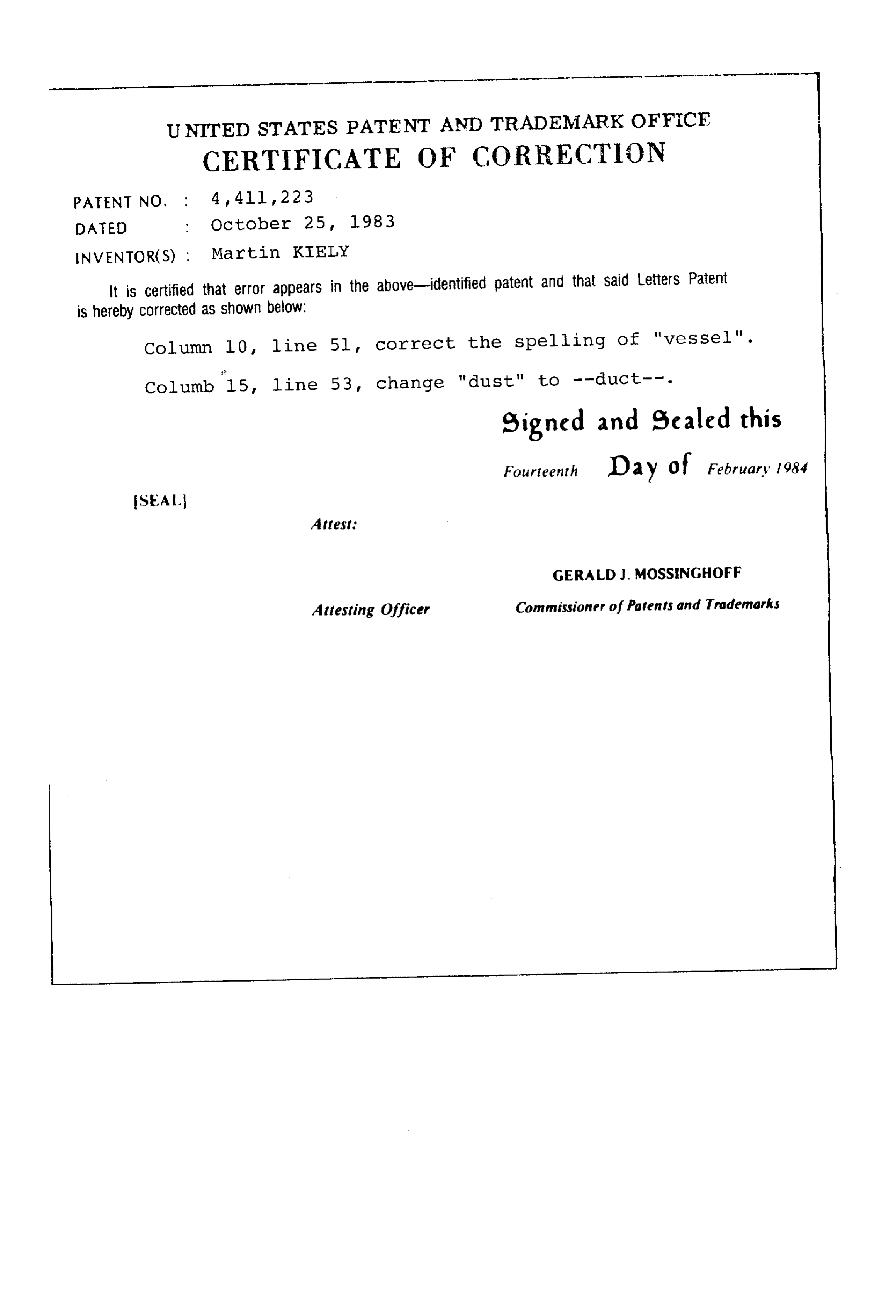
UNITED STATES PATENT AND TRADEMARK OFFICF
CERTIFICATE OF CORRECTION
NVENTOR(S) : Martin KIELY it is certified that error appears in the above-identified patent and that said Letters Patent is hereby Corrected as shown below:
Column l (), line 5l, correct the spelling of "vessel". Columb 15, line 53, change "dust" to --duct--. eigned and Scaled this
Fourteenth Da y of February 1984
SEAL
Attest:
GERALD J. MOSSINGHOFF
Attesting Officer Commissioner of Parents and Tradenarks
Provenance
- Collection
- Cited prior art
- Original PDF
- patentimages.storage.googleapis.com →
- Filed
- 1981-06-19
- Pages
- 17
- Method
- pdftotext (the PDF's own text layer) + pdftoppm 300dpi page scans
- Source
- Google Patents bibliographic record
- Granted
- 1983-10-25
- Inventors
- Martin Kiely
- Transcribed from
- patentimages.storage.googleapis.com →