patent · US3933614
Pressure vessel for hydrogen generator
20 January 1976
Page 1 — bibliographic record
United States Patent (19) 11 3,933,614 Bunn, Jr. (45) Jan. 20, 1976 54 PRESSURE WESSEL FOR HYDROGEN 3,346,470 10/1967 Henes.............m 204/29 GENERATOR 3,448,035 6/1969. Serfass..................... ... 204/266 X
(75) Inventor: Julian W. Bunn, Jr., Raleigh, N.C.
(73) Assignee: Trienco, Inc., Raleigh, N.C. Primary Examiner-T. Tung
Assistant Examiner-A. C. Prescott 22) Filed: July 7, 1975 Attorney, Agent, or Firm-B. B. Olive; Richard S. (21) Appl. No.: 593,751 Faust
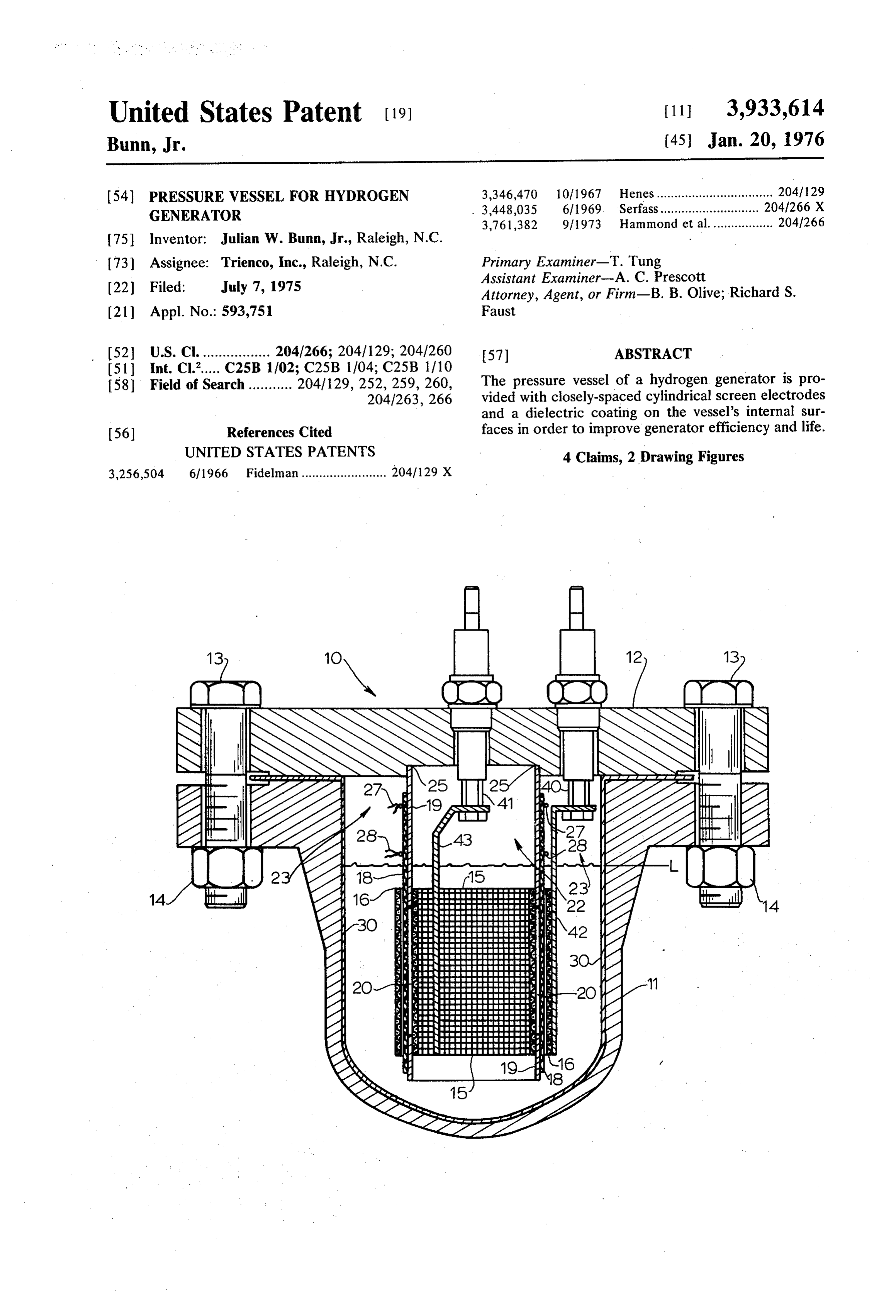
(52) U.S. Cl. ................. 204/266; 204/129; 204/260 57 ABSTRACT (51) Int. Cl...... C25B 1/02; C25B 1704; C25B 1/10 The pressure vessel of a hydrogen generator is pro 58 Field of Search ........... 204/129, 252, 259, 260, vided with closely-spaced cylindrical screen electrodes
and a dielectric coating on the vessel's internal sur (56) References Cited faces in order to improve generator efficiency and life. UNITED STATES PATENTS 4 Claims, 2 Drawing Figures 3,256,504 6/1966 Fidelman........................ 204/129 X
Ramaya
Page 2
Drawing sheet — no readable text.
Page 3
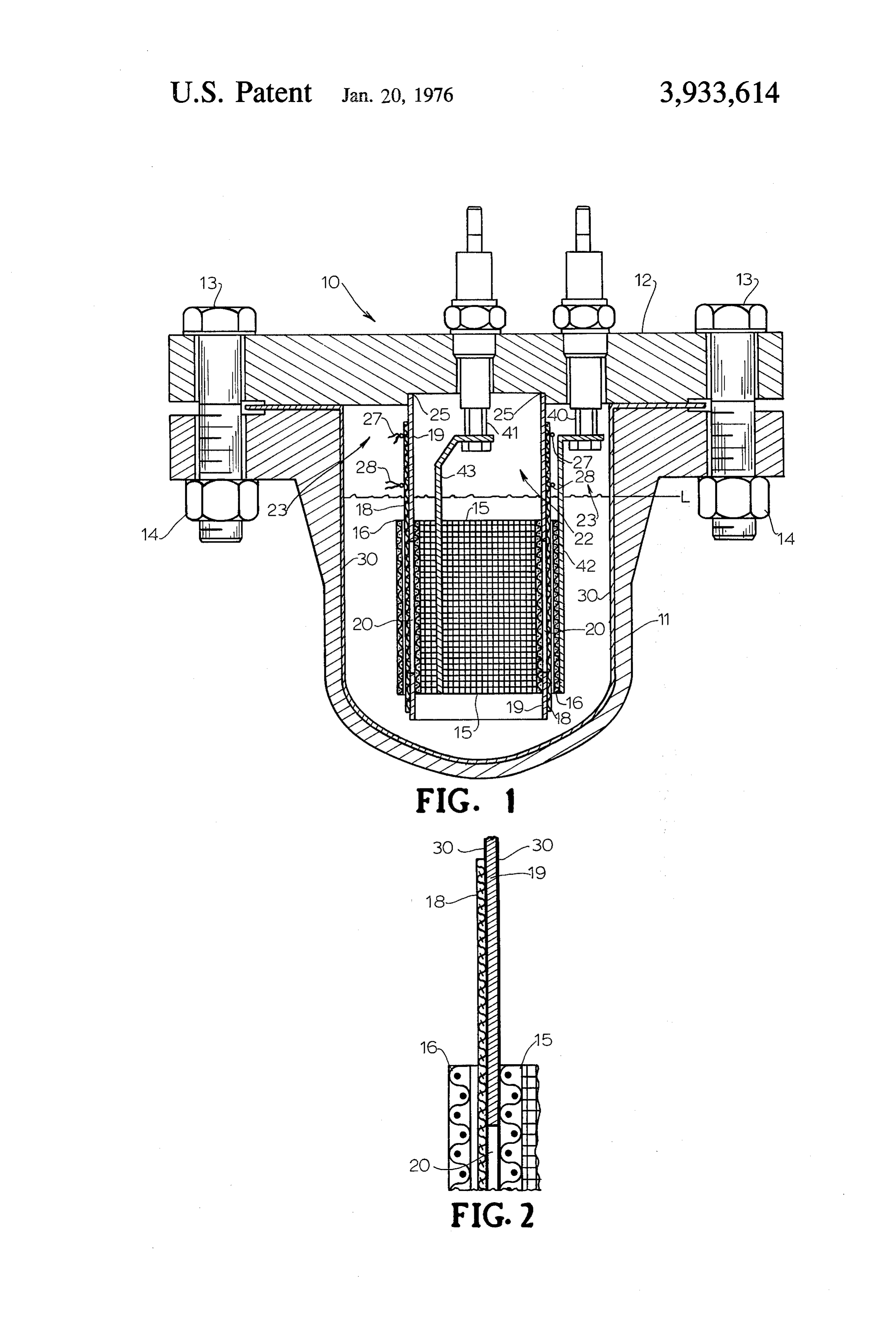
DESCRIPTION OF THE DRAWINGS
PRESSURE WESSEL FOR HYDROGEN
GENERATOR FIG. 1 is a section view of the pressure vessel showing the position of the hydrogen and oxygen electrodes and
BACKGROUND OF THE INVENTION 5 with the water inlet, hydrogen and oxygen outlets, and 1. Field of the Invention: level control means not shown but with the invention The invention relates to apparatus for generating improvements
FIG. 2 is an being shown.
enlarged section view of the electrodes, hydrogen, more specifically to the internal construc tube member and asbestos sleeve shown in FIG. 1. tion of the pressure vessel of such a generator. O 2. Description of the Prior Art: DESCRIPTION OF THE PREFERRED It is a well-known process to obtain hydrogen from EMBODIMENT the disassociation of water by electrolysis. Hydrogen As best shown in FIG. 1, pressure vessel 10 comprises generators using this principle generally employ a pres a tank member 11 and top member 12. In specific surized container in which the electrodes are situated 15 embodiment, tank 11 is a standard 4-inch weld cap and the oxygen and hydrogen gases are collected sepa welded to a standard 4-inch weld neck flange and top rately. U.S. Pat. No. 3,761,382 represents an important member 12 is a 4-inch blind flange. Members 11 and 12 improvement in the generation and purification of hy are secured together in a gas-tight seal by bolts 13 and drogen. The novel pressure vessel of this patented gen nuts 14. Tank 11 encloses four cylindrical components: erator includes a tank member which is hermetically 20 hydrogen electrode 15, oxygen electrode 16, asbestos secured to a closed top member. A controlled volume curtain 18, and tube member 19, which are arranged in of electrolytic solution is maintained in the tank during a closely spaced, concentric manner. operation. The hydrogen electrode (cathode) com Thin-wall, slotted tube member 19 is secured in a prises a cylindrical probe member which is mounted in 25 gas-tight connection 25 to the interior surface of top the center of the tank. An open-ended, cylindrical member 12 and extends downwardly within tank 11 to screen oxygen electrode (anode) surrounds the hydro asurface point approximately one-half inch from the bottom of tank 11. Tube 19 is made from 20-gauge gen electrode. The electrodes are spaced by a plastic carbon steel cylindrical sleeve member and a woven asbestos sleeve slots 20 whichand is provided with a plurality of vertical leave only sufficient skeleton to support
COWe.
The pressure vessel of the patented generator has woven asbestos curtain 18. Curtain 18 is wrapped
been found to have several drawbacks. First, an appre around tube 19 and secured by strings 27, 28. Curtain 18 covers slots 20 and prevents the passage of either ciable electrical flow from the anode to the internal oxygen or hydrogen through the slots. . . . . wall of the pressure vessel has resulted in reduced effi An oxygen electrode terminal 40 extends through top ciency of the generator. Second, the approximate 4 35 12 into tank 11. Attached to terminal 40 is an electrode inch space between the anode and cathode has resulted connector 42 which connects terminal 40 to the oxygen in a relatively high resistance to current flow between electrode screen 16. Electrode screen 16 is located anode and cathode. By reducing the space between immediately outside of asbestos curtain 18. In specific anode and cathode, the generating capacity of the gen embodiment, electrode 16 is made from a nickel 200 erator can be improved by increasing the current flow 40 screen having 12 by 12 mesh and 0.032 inch diameter for a given voltage. The high resistance has also caused wire. Electrode 16 serves as the anode in the electroly the generator to run at elevated temperatures thereby sis process. Screen electrode 16 covers and extends reducing the life of the asbestos screen and other inter slightly above and below slots 20 in tube 19. The stain nal components. Third, the vessel interior surface is 45 less steel hydrogen electrode screen 15 is connected to continuously exposed to a 18% solution of sodium 43. hydrogen electrode terminal 41 by electrode connector hydroxide, oxygen and hydrogen. It has been found Electrode 15 is made from 304 stainless steel that these substances corrode and otherwise tend to screen having 14 by 14 mesh and 0.025 inch wire. deteriorate the interior surfaces of the pressure vessel. the Electrode 15 is mounted inside of tube 19 to serve as It is the purpose of the present invention to overcome 50 16 arecathode. As best shown in FIG. 2, electrodes 15 and the disadvantages while maintaining the many advan and tubeseparated 19.
only by the thicknesses of curtain 18 tages of the generator pressure vessel of U.S. Pat. No. Slots 20 in tube 19 allow for the passage of ions be 3,761,382. tween the electrodes 15, 16 while the asbestos curtain SUMMARY OF THE INVENTION 18 serves as a barrier to the flow of gas through the 55 slots. The 20-gauge steel construction of tube 19 pro
The apparatus of the invention provides a novel pres vides a 0.0375 inch wall thickness. It has been found sure vessel construction for electrolytic hydrogen or that this approaches the minimum wall thickness which oxygen generators. The pressure vessel includes a top will provide structural integrity at operating tempera member which is hermetically secured to a tank mem tures. As discussed previously, the thickness of tube 19 ber. Appropriate openings are provided in the top for 60 determines the distance between electrodes 15 and 16. introducing water into the tank, removing hydrogen By placing electrodes 15, 16 in a close spatial relation and oxygen gas from the tank and securing the hydro ship, the resistance to electrical flow between the elec gen and oxygen electrode terminals. The tank houses trodes is decreased thereby increasing the hydrogen the hydrogen and oxygen electrodes which are cylindri output per unit of electrical energy consumed. A fur cal screen members separated only by a woven asbestos 65 ther advantage of placing the electrodes close together curtain and an electrically insulated, thin-wall steel is that heat generation is kept at a minimum thereby tube. The interior surface of the tank is also electrically increasing the life of the internal components. Tube 19 insulated to prevent power loss to such surface. is made from an electrical conducting material; and,
Page 4
therefore, it must be coated with an insulating coating What is claimed is:
30 since it may be in physical contact with electrode 15 1. In an electrolytic hydrogen or oxygen generator and is positioned only a short distance from electrode apparatus of the type having a pressure tank adapted to 16. The preferred coating is No. ECB-136A Epoxy contain an electrolytic solution including water and an manufactured by Polymer corporation of Reading, 5 electrolyte, and having a water inlet, an oxygen outlet Pennsylvania. Polymer Epoxy No. ECA-1283 and cer and a hydrogen outlet, the improved pressure tank tain polyvinyl chlorides with good dielectric qualities assembly comprising, in combination: have also been used successfully. It has been found that a. a metal tank member having a closed bottom and if the interior wall surface of tank 10 is made from an an open top, electrical conducting material, there will be a power 10 b. a cover member hermetically secured to the open loss due to electrical flow from electrode 16 to the wall top of said tank member, said cover member pro surface; therefore, the interior wall surface of tank 11 is viding openings for said water inlet, oxygen outlet coated with coating 30, as used on tube 19. and hydrogen outlet;
The operation of pressure vessel 10 will now be de c. a thin-wall integral cylindrical tube member having scribed. Before start-up, the level of the electrolytic 15 electrically insulating surfaces and positioned cen solution in tank 11 is brought to level L which is suffi trally inside of said tank member, the upper end ciently high to assure that the solution completely cov portion of said tube member being connected to ers electrode screens 15 and 16. An electric potential is said cover member in a gas-tight seal and having a created between electrodes 15 and 16 thereby generat lower open end portion terminating immediately ing oxygen and hydrogen by electrolysis in the manner 20 above the closed bottom surface of said tank mem well known to those skilled in the art. Oxygen collects ber and including openings cut therein; in oxygen collection space 23 and hydrogen collects in d. a woven, cylindrical asbestos curtain covering said hydrogen collection space 22. Gas-tight seal 25 pre tube openings and adapted to act as an impervious vents mixing of the gases. The oxygen is bled to the atmosphere from collection space 23 through a suitable 25 allowingtothehydrogen barrier passage and oxygen gas flow while of ions and electrolytic solu relief valve (not shown) and the hydrogen is conveyed tion therethrough;
from the generator through suitable tubing (not shown) e. oxygen electrode means mounted inside said tank at such rates that the level of caustic fluid remains at a satisfactory level for further electrolysis. Suitable con member and having electrically conducting means trol means (not shown) are provided to keep the elec-30 trode meansthrough extending said cover, said oxygen elec comprising a fine mesh screen elec trolytic solution at operative levels. trode wrapped in close spaced relation around said In summary, the novel and efficient construction of asbestos curtain and covering said tube openings; pressure vessel 10 leads to increased efficiency in the f. hydrogen electrode means mounted inside said operation of a hydrogen generator of the type de scribed in U.S. Pat. No. 3,761,382. The epoxy coating 35 tank member and having electrically conducting 30 on the interior wall surface of tank 11 prevents means extending through said cover, said hydrogen corrosion due to the continuous exposure to the caustic electrode means comprising a fine mesh screen electrolytic solution. Coating 30 also serves to insulate electrode positioned inside of said tube and being the tank wall from electrode screen 16 thereby elimi coaxial with said tube in a close spaced relation nating any electrical flow from electrode 16 to the wall. 40 therewith said tube and having a height sufficient to cover
By coating slotted tube member 19 with coating 30, it is possible to use an electrically insulated, thin-wall g- an electrically insulating coating impervious to and steel tube instead of the thicker plastic tube members inert with respect to hydrogen, oxygen, and sodium of the prior art. As a result there is a close spatial rela hydroxide applied to the entire interior side and tionship between electrodes 15 and 16 which reduces 45 bottom wall surfaces of said tank member. the resistance between electrodes and allows a higher 2. The apparatus of claim 1 wherein said oxygen current flow at a constant voltage. It has been found electrode screen is a nickel screen and said hydrogen that this reduction in electrical resistance allows the electrode screen is a stainless steel screen. hydrogen generator to produce approximately 25% 3. The apparatus of claim 1 wherein said tube is made more hydrogen at constant power consumption. The 50 of steel having a thickness less than 0.040 inches and lower resistance also cuts back on heat generation in covered with an electrically insulating coating selected tank 11 and thereby increased the life of the internal from the group consisting of epoxy and polyvinyl chlo components. ride.
Since the present invention follows. U.S. Pat. No. 4. The apparatus of claim 1 wherein said electrically 3,761,382, a more complete understanding of the in- 55 insulating coating applied to the interior surfaces of vention, its advantages and operation, may be had by said tank member is selected from the group consisting resort to that patent and whose teachings have not been of epoxy and polyvinyl chloride. repeated here. : k . . .
Provenance
- Collection
- Cited prior art
- Original PDF
- patentimages.storage.googleapis.com →
- Filed
- 1975-07-07
- Pages
- 4
- Method
- pdftotext (the PDF's own text layer) + pdftoppm 300dpi page scans
- Source
- Google Patents bibliographic record
- Granted
- 1976-01-20
- Inventors
- Julian W. Bunn, Jr.; Trienco Inc
- Transcribed from
- patentimages.storage.googleapis.com →