patent · US4124463
Electrolytic cell
7 November 1978
Page 1
United States Patent (19) 11) 4,124,463 Blue 45) Nov. 7, 1978 54) ELECTROLYTC CELL (56) References Cited
(75) Inventor: Archie H. Blue, Christchurch, New
Zealand 1,219,333 3/1917 Kynaston ......................... 204/149 X 1,376,207 4/1921 Jacobs .............................. 204/265 X 1,431,047 10/1922 Ruben .................................. 204/265 73) Assignees: Ross Derisley Wood; Roland Edgar; 1,544,052 6/1925 Avery .............................. 204/149 X Alec Henry Taylor, all of St. Martin's 1,862,663 6/1932 Curtis .............................. 204/288 X Guernsey, Channel Islands; 2,000,815 5/1935 Berl.................................. 204/265 X Margaret Elizabeth Pyke, Essex, 3,192,138 6/1965 Enk et al. ........................ 204/246X England 3,433,729 3/1969 Proskuryakov et al. ........ 204/129 X 3,518,036 6/1970 Staats et al. ..................... 204/129 X (21) Appl. No.: 755,608 Primary Examiner-Arthur C. Prescott Attorney, Agent, or Firm-Haseltine, Lake & Waters
(51 Int, Cl’.......................... C25B 1/02; C25B 9/00; In the electrolytic production of hydrogen and oxygen, C25B 9/02 air is pumped through the cell while the electrolysis is in 52 U.S. C. .................................... 204/129; 204/265; progress so as to obtain a mixture of air with the electro 204/277; 204/288 lytically produced hydrogen and oxygen.
204/266, 269, 270, 277,278, 275, 288, 289 5 Claims, 3 Drawing Figures
III
Page 2
Drawing sheet — no readable text.
Page 3
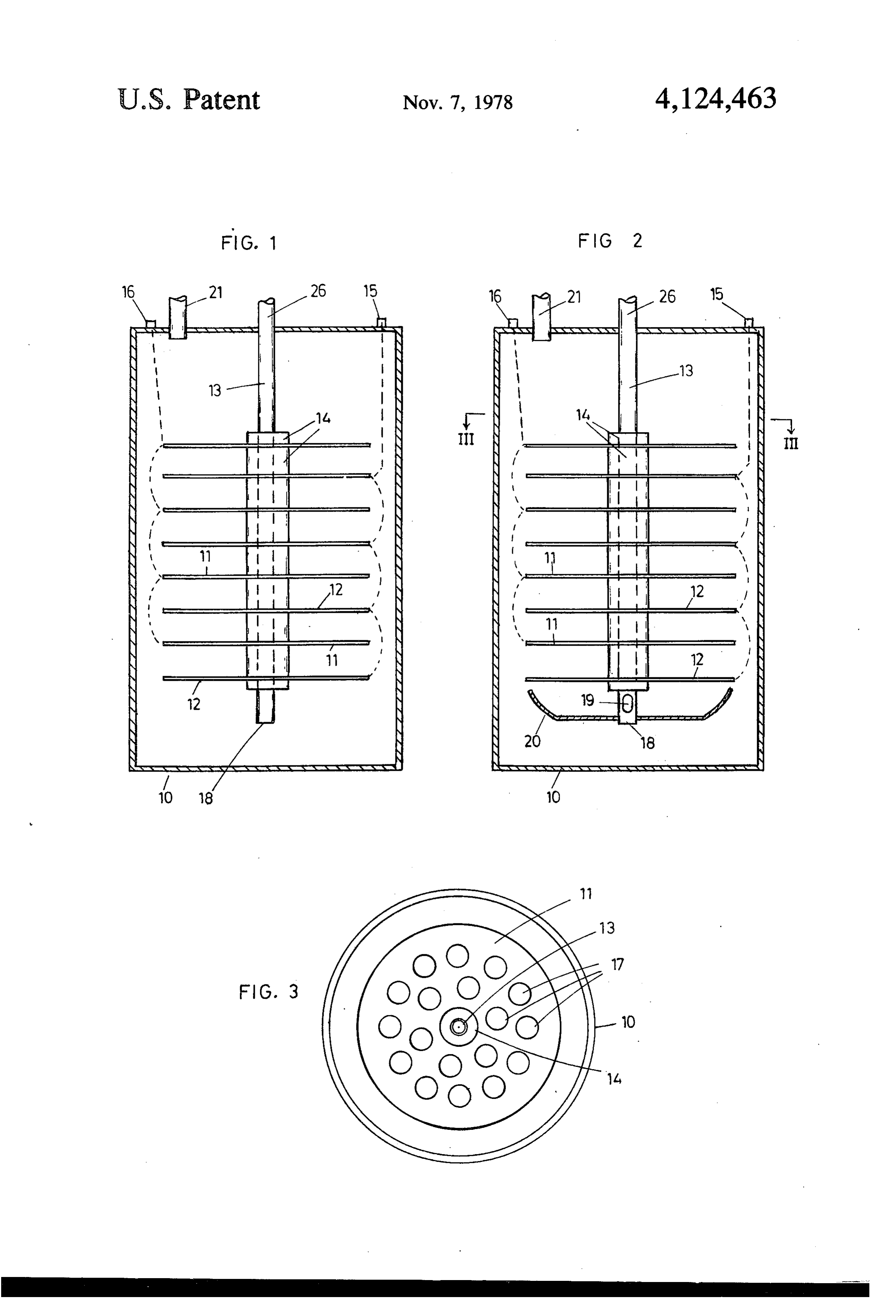
insulating central post 13, with the cathodes and anodes
ELECTROLYTIC CELL being spaced apart by means of insulating spacers 14. The anodes 12 are all connected in parallel to a positive
BACKGROUND AND BRIEF DESCRIPTION OF 5 parallel topost terminal the 15 while the cathodes are all connected in negative terminal post 16, these connec
THE INVENTION.
tions being indicated in dotted lines in the drawings.
This invention relates to the production of gases The cathodes and the anodes are preferably in the form which can be utilized primarily but not necessarily as a of disc like plates of a suitable metal which is consistent fuel. , with the composition of the electrolyte utilized so as to To electrically decompose water it is necessary to 10 ensure a satisfactory life to the cell. The plates may be pass direct current between a pair of electrodes which shaped to conform with the shape of the walls of the are immersed in a suitable electrolyte. It is normal in cell which may be circular in cross section as indicated such electrolysis to place some form of gas barrier be or any other desired shape.
tween the two electrodes in order to prevent the gases The central post 13 is preferably in the form of a tube evolved during the electrolysis from forming an explo 15 which extends out of the cell as at 13a. The lower end sive mixture. However provided suitable precautions 18 of the tube is open so that air can be pumped into the are taken it has been found that the gases can be allowed cell through the central post 13 and enter the cell via the to mix and can be fed into a storage tank for subsequent lower end 18 where it will pass up through the electro use. Because the gases when mixed form an explosive lyte. This will keep the electrolyte constantly in motion mixture, it is possible for the mixture to be utilized for 20 and thereby assist in the rapid removal from the elec instance as a fuel for an internal combustion engine. In trodes of any gases that might be adhering thereto. such circumstances it is desirable that the gases should In the modification shown in FIG. 2 and 3, the elec also be mixed with a certain proportion of air in order to trodes are each provided with holes 17 and in such a control the explosive force which results when the case the central post 13 is preferably formed with at gases are ignited. 25 least one air hole 19 adjacent the lower end 18 thereof. One of the difficulties encountered with electrolysis A deflector plate 20 is also supported by the central post is that bubbles of gas are liable to remain on the elec 13, this plate being dish shaped so as to deflect air issu trodes during the electrolysis thus effectively limiting ing out of the air hole 19 up through the holes 17 in the the area of electrode which is in contact with the elec electrodes. Such action further assists in dislodging any trolyte and preventing optimum current flow between 30 bubbles of gas clinging to the electrodes. the electrodes. Because in accordance with the present The cell also includes a gas outlet 21 so that the air invention it is desirable that the gases evolved during which enters the cell together with the gases produced the electrolysis be mixed with air, then it is possible for by the electrolysis can be exhausted out of the cell into air to be passed through the cell while the electrolysis is a suitable storage tank (not shown in the drawings). If in progress. The passage of air through the cell can be 35 desired such storage tank can be arranged to accept the directed past the electrodes so as to entrain in the pas gases under pressure and for this purpose the air sage of air any bubbles of gas remaining on the elec pumped into the cell will be pumped in under the re trodes. quired pressure. A gas drier (not shown in the draw Accordingly the invention comprises an electrolytic ings) can also be interposed between the gas outlet 21 cell including a gas tight casing, a plurality of electrodes and the storage tank.
adapted to be supported on a central post within the cell Although the electrolysis will naturally produce con in a spaced apart relationship and to be electrically siderable heat, nevertheless it can be found advanta insulated from each other, each alternative electrode geous to install a heater in the cell, preferably in the being adapted to be connected to a positive direct cur bottom of the cell, to assist and facilitate the warming rent source or a negative direct current source respec 45 up of the electrolyte so that the cell reaches its most tively and wherein the central post is in the form of a efficient operating conditions as quickly as possible. tube, one end of which is extended out of the cell and is Preferably also, current limiting means as is known in adapted to be connected to a source of air under pres the art are employed so that the intensity of the electro sure, with the other end of the central post terminating lytic action can be controlled.
in an air outlet below the said electrodes, the said cell 50 Means may also be provided for the automatic re including a gas outlet to exhaust air forced into the cell plenishment of water within the cell as the level of the through the central post and to exhaust the electrolyti electrolytic drops during use.
cally produced gases mixed with the said air. While it is recognized that the mixing of hydrogen DETAILED DESCRIPTION OF THE and oxygen will create a dangerous explosive mixture, 55 nevertheless by carrying out the invention as hereinbe
INVENTION
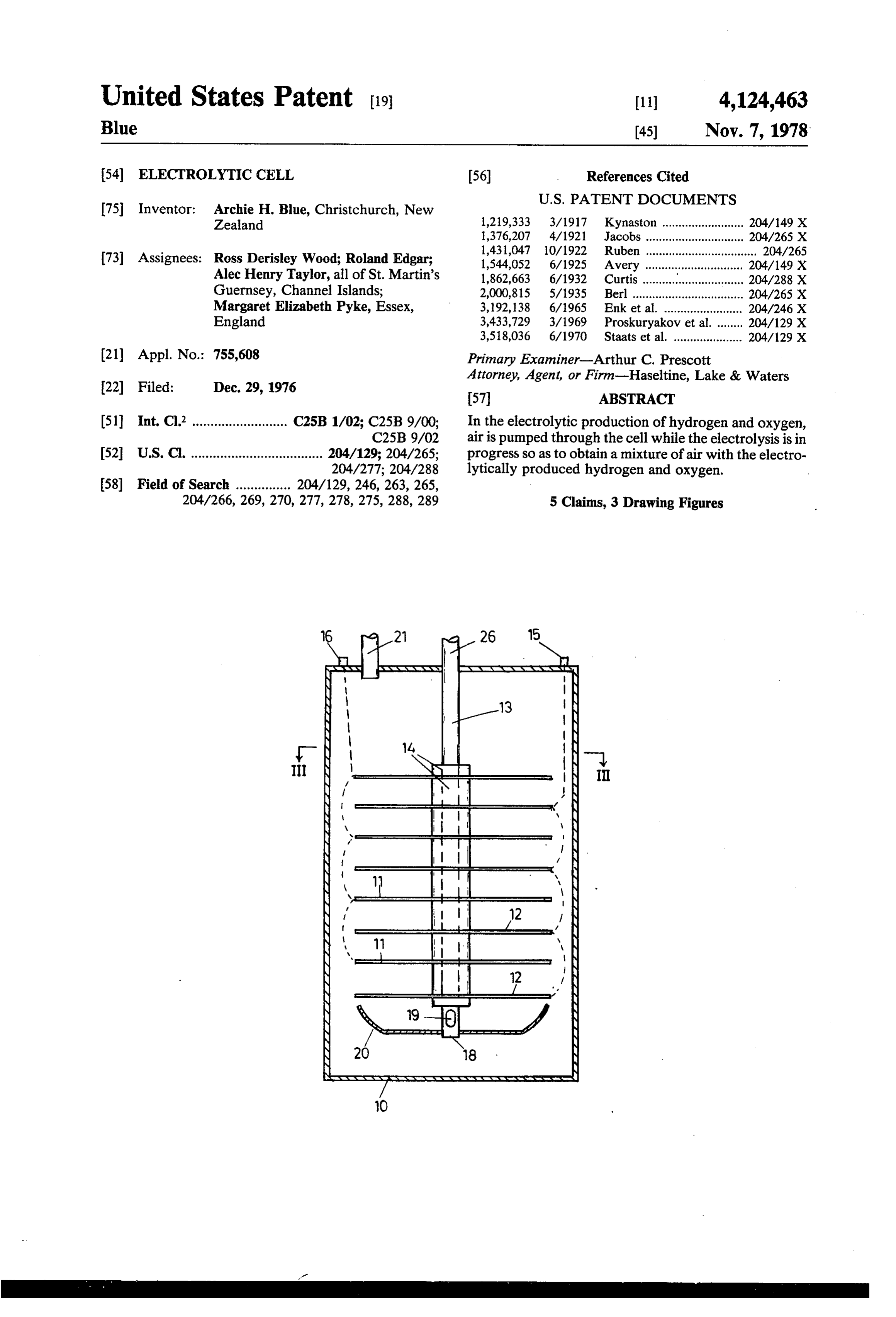
Various forms of the invention will now be described fore described the risk of explosion is minimized. The gases produced can be utilized for instance as a fuel to with the aid of the accompanying drawings wherein: power an internal combustion engine and for this pur FIG. 1 is a diagrammatic elevational view partly in pose it is desirable, as beforementioned, to mix with the section of one form of the invention, gases evolved during the electrolysis a proportion of air FIG. 2 is a diagrammatic elevational view partly in so that when the mixture is ignited within the cylinder section of a modified form of the invention, or cylinders of the engine, the explosive force so cre FIG. 3 is a section along the line III-III of FIG. 2. ated can be of the desired amount.
The cell as shown in FIG. 1 comprises a gas-tight While in the foregoing description reference is made casing 11 which is formed from a non-corrodible mate 65 to the utilization of the mixed gases as a fuel, it will of rial such as a plastics material as is known in the art. A course be understood that the gases can be separated for plurality of cathodes 11 and a plurality of anodes 12 are individual use by techniques as known in the art. supported within the cell by means of an electrically What is claimed is:
Page 4
1. A process for producing by electrolysis of an aque 3. The process according to claim 1 further including ous liquid a combustible mixture of hydrogen and oxy a dish-shaped air deflector plate supported on the said gen, comprising: electrolyzing the aqueous liquid into post below the said air outlet. 4. Apparatus for producing by electrolysis of an aque hydrogen and oxygen in an electrolytic cell having a 5 ous liquid a combustible mixture of hydrogen and oxy gas-tight casing, a substantially central tubular post gen, comprising: an electrolytic cell having a gas-tight mounted in the casing and having an air inlet at its upper casing, a substantially central tubular post mounted in end, and a plurality of electrodes supported on the post the casing and having an air inlet at its upper end, and a plurality of electrodes supported on the post and axially and axially spaced therealong, alternate electrodes 10 spaced therealong, alternate electrodes being connected being connected to a first electrical terminal and to a to a first electrical terminal and to a second electrical second electrical terminal respectively connected to a terminal respectively for connection to respective poles respective poles of a current source and being mutually of a current source and being mutually insulated, the insulated, the post having an air outlet below the elec 15 of airhaving post an air outlet below the electrodes for flow from the air inlet into the cell and over the elec trodes out of which flows air from the air inlet into the trodes; a dish-shaped air deflector supported on said cell and over the electrodes; and a source of air under post below said air outlet; and a source of air under pressure connected to the said air inlet forcing a flow of pressure connected to the said air inlet for forcing a flow of air through the aqueous liquid contained in the air through the aqueous liquid contained in the cell in 20 cell in operation thereof; the cell having in its upper operation thereof; the cell having in its upper region a region a common outlet for exhausting the combustible common outlet exhausting the combustible mixture mixture comprising air forced through the cell and comprising air forced through the cell and hydrogen hydrogen and oxygen produced by electrolysis of said produced by electrolysis of said liquid in said cell. liquid in said cell.
2. The process according to claim 1 wherein the electrodes 5. The apparatus according to claim 4 wherein the are discs each having a plurality of holes electrodes are discs each having a plurality of holes therethrough.
therethrough.
Provenance
- Collection
- Cited prior art
- Original PDF
- patentimages.storage.googleapis.com →
- Filed
- 1976-12-29
- Pages
- 4
- Method
- pdftotext (the PDF's own text layer) + pdftoppm 300dpi page scans
- Source
- Google Patents bibliographic record
- Granted
- 1978-11-07
- Inventors
- Archie H. Blue
- Transcribed from
- patentimages.storage.googleapis.com →