patent · US4344831
Apparatus for the generation of gaseous fuel
17 August 1982
Page 1 — bibliographic record
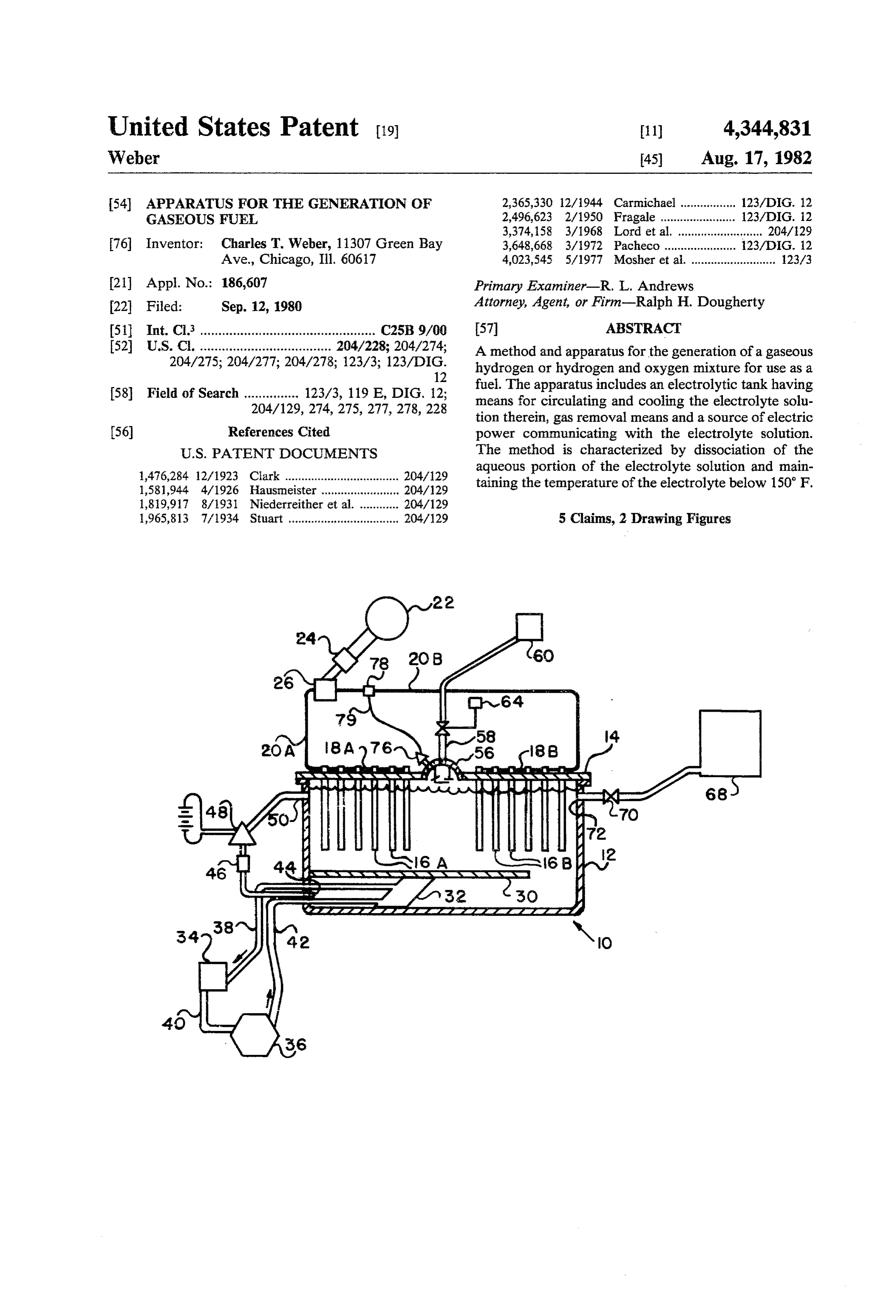
United States Patent (19) 11 4,344,831 Weber 45) Aug. 17, 1982 54 APPARATUS FOR THE GENERATION OF 2,365,330 2/1944 Carmichael ................. 123/DIG. 12 GASEOUS FUEL 2,496,623 2/1950 Fragale ..... ... 123DCG. 2 3,374,158 3/1968 Lord et al. ....................... 204/129 76 Inventor: Charles T. Weber, 11307 Green Bay 3,648,668 3/1972 Pacheco ........... 23ADIG. 12 Ave., Chicago, Ill. 60617 4,023,545 5/1977 Mosher et al. .......................... 123/3 21 Appl. No.: 186,607 Primary Examiner-R. L. Andrews 22 Filed: Sep. 12, 1980 Attorney, Agent, or Firm-Ralph H. Dougherty 51 Int. Cli................................................ C25B 9/00 57 ABSTRACT 52 U.S. C. .................................... 204/228; 204/274; A method and apparatus for the generation of a gaseous 204/275; 204/277; 204/278; 123/3; 123/DIG. hydrogen or hydrogen and oxygen mixture for use as a
58 Field of Search ............... 123/3, 119 E, DIG. 12; fuel. The apparatus includes an electrolytic tank having 204/129, 274, 275, 277,278, 228 means for circulating and cooling the electrolyte solu tion therein, gas removal means and a source of electric 56) References Cited power communicating with the electrolyte solution.
1,476,284 12/1923 Clark ................................... 204/129 aqueous portion of the electrolyte solution and main 1,581,944 4/1926 Hausmeister ........................ 204/129 taining the temperature of the electrolyte below 150 F.
1,965,813 7/1934 Stuart .................................. 204/129 5 Claims, 2 Drawing Figures
, all 5
Page 2
Drawing sheet — no readable text.
Page 3
APPARATUS FOR THE GENERATION OF DETALED DESCRIPTION
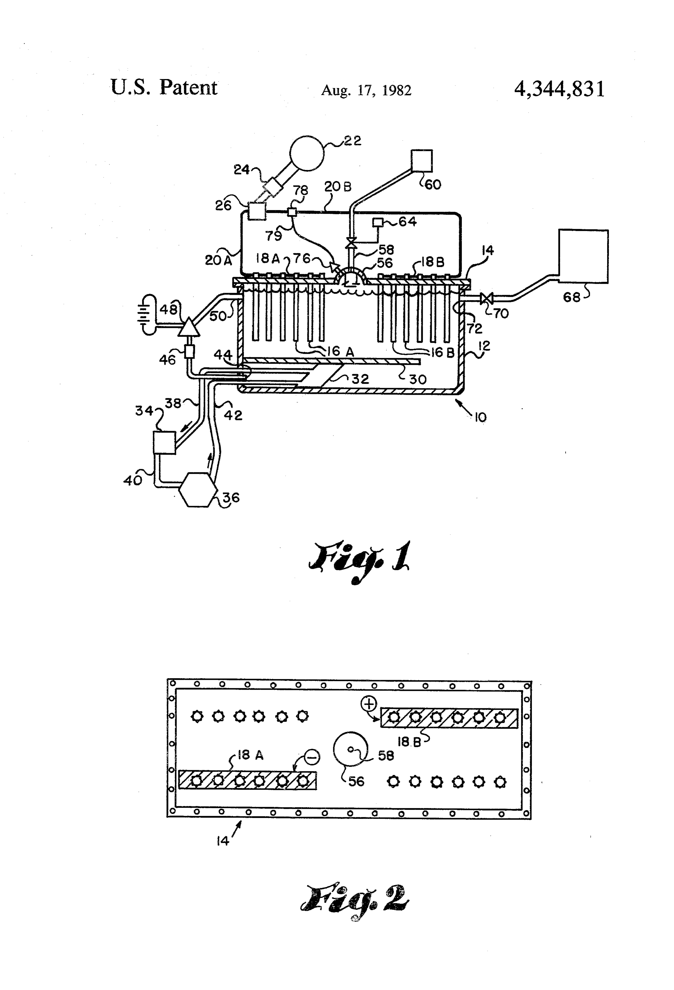
GASEOUS FUEL Referring now to FIG. 1, electrolysis unit 10 includes a tank 12 for containing electrolyte fluid, and having a
BACKGROUND OF THE INVENTION 5 cover 14 sealingly engaging tank 12. A plurality of The present invention relates to the generation of electrodethe anodes plates 16-A and 16-B depend from cover 14;
16-A are connected to bus bar 18-A exterior gaseous fuel for internal combustion engines, particu to tank 2, whereas larly for such engines which use petroleum products to bus bar 18-B. The the bus cathodes 16-B are connected to bars are connected through form explosive mixtures when vaporized in air.
It has long been known that internal combustion power leads 20-A and 20-B to an alternating current
engines can be fueled by a mixture of hydrogen and generator 22. The generator may be mounted on the oxygen as well as by the standard vaporized petroleum rent passes driven engine and through by it; preferably the generator cur a full bridge rectifier 24 and an products. However, until recently, there has been no alternating current filter method for generating hydrogen in a practical manner 15 the bus bars. This results26inbetween direct the generator and current being sup which would avoid the problem of storage of hydrogen plied to the bus bars.
prior to use. When hydrogen is generated from water, it The lower part of tank 12 is separated from the upper occupies many times the volume of the liquid water part by a separator or baffle 30 which extends across the from which it is generated. Thus, storage facilities must tank and is open at one end. Within the lower chamber be under high pressure at low temperature, which re 20 formed by the bottom of the tank and baffle 30 is an quires additional power input to compress and cool the evaporative cooler 32 which is provided with a con hydrogen, or the hydrogen must be stored in large tanks denser 34 exterior to the tank and compressor 36 along which are unsuitable for connection to an internal com with the necessary conduits 38, 40 and 42 for recirculat bustion engine. In either case, the storage of hydrogen is ing the cooling fluid within the system. extremely inefficient. 25 At the end of the lower chamber opposite the baffle In the past several years, atmospheric pollution has opening is a fluid outlet 44. Fluid is cooled by passing it increased many-fold from automotive emissions due to around evaporator-cooler 32, then removed from the the fact that the burning of petroleum-based fuels results lower chamber at outlet 44, passed through filter 46 and in the production of carbon monoxide and carbon diox recirculating pump 48, then the electrolyte fluid is in ide which are emitted into the atmosphere. Internal 30 jected into the upper chamber through inlet 50. combustion engines powered by hydrogen or a mixture A dome 56 in cover 14 is provided for the accumula of hydrogen and oxygen result in the emission of a small tion of gases. The dome is so constructed that fluid does amount of hydrogen, a small amount of oxygen and not enter the product gas conduit. Outlet pipe 58 is principally water in the forms of liquid or vapor, none 35 connected to the apex of the dome to remove the prod of which pollute the atmosphere. uct gases formed within the electrolytic cell. The fuel It is preferable that both hydrogen and oxygen be gas conduit communicates with a carburetor 60 or an provided in gaseous form to an internal combustion intake manifold of an internal combustion engine. Valve engine in ready-to-burn form. The present invention 62 is provided in the conduit 58 to shut off the flow of achieves this aim by employing an electrolytic cell hav gas to the carburetor upon command of solenoid 64; that is, when the ignition is not on, the solenoid 64 ing a plurality of carbon-plate electrodes divided into an closes valve 62.
equal number of anodes and cathodes, a source of water Make up water may be provided from water reser for injection into the cell, an electrolyte in solution in the water and a cell cooler located within the cell to voir 68 through valve 70 and water inlet 72 to the inte maintain the temperature of the cell at a desired low 45 riorA ofpressure the tank 12.
regulator 76 is mounted in dome 56 to level.
Although this invention is principally applicable to monitor the gas pressure within the dome. Pressure regulator 76 is connected to electrical switch 78 by internal combustion engines, the gaseous fuel product is connecting wire 79. Alternatively switch 78 can be a suitable for heating or any other fuel use. voltage regulator to vary the voltage within the electri OBJECTS OF THE INVENTION 50 cal circuit or to open and close the circuit. The principal object of the present invention is to addition In operation, an electrolyte fluid is formed by the provide a method for generating a hydrogen-oxygen cell. Sodium of a salt to the water within the electrolytic chloride and calcium chloride are suitable fuel suitable for powering internal combustion engines. salts. The fluid level is maintained to the top of the Another object of this invention is to provide appara 55 tus for powering an internal combustion engine which carbon rather plates 16. The electrodes are made of carbon than any other material, as I have found carbon will reduce polluting emissions into the atmosphere. to be resistant to disintegration during electrolysis. Another object of this invention is to provide a means An external source of power is required to start the for powering a vehicle utilizing water as one of the generation of gaseous fuel in electrolytic cell 10. When basic sources of energy. this source of power is the internal combustion engine BRIEF DESCRIPTION OF THE DRAWINGS for which the cell generates fuel, the engine must be started by utilizing stored gaseous fuel or some outside
The foregoing and other objects of this invention will source of power. As soon as hydrogen generation in cell be better understood from the following detailed de i0 is sufficient to raise the pressure within dome 56 to a scription and the appended drawings in which: 65 sufficient level to operate the engine, solenoid 64 is FIG. 1 is a schematic cross-section of my electrolytic actuated to open valve 62 and the hydrogen-oxygen cell apparatus showing the necessary connections. fuel gas flows to carburetor 60. Fluid is recirculated, FIG. 2 is a top view of the cell of FIG. 1. filtered and cooled by removing it from the tank
Page 4
through outlet 44, pumping it by pump 48 through filter generating a gaseous fuel useful as a heat source as well 46 and reinjecting it into the upper section of the elec as in an internal combustion engine which is non-pollut trolytic cell through water inlet 46 from which it passes ing, the materials for which are readily available in all through and around electrode plates 16, around the end parts of the world.
of baffle 30, then through and around the bins of 5 What is claimed is:
evaporator-cooler 32 and out of the cell. Filter 46 is 1. Apparatus for the electrolytic generation of a hy optional, but is preferable to remove any particulate drogen-oxygen fuel mixture comprising: matter which may form within the cell, foam or impuri an electrolytic tank containing an electrolyte solution ties from the water. Distilled water or tap water can be and having a plurality of carbon electrodes sus employed. In addition, aqueous solutions of ammonia 10 pended therein;
and some mild acids are also suitable electrolytes. a horizontally extending baffle in said tank beneath The salt concentration in the cell controls the amper said electrodes partially dividing said tank into an age passing through the electrolyte, and the greater the upper chamber and a lower chamber, said baffle current, the larger the amount of dissociated gases being open at one end;
formed. Thus if a greater amount of current is desired 15 a recirculating electrolyte line communicating with for a given voltage, more salt is added to the cell. The the upper chamber of said tank and with the closed amperage will also vary with the electrolyte level. As end of said lower chamber and having solution the level falls, the salt concentration increases, and with recirculating means therein; it the generation of gas increases. means connected to said tank for cooling the electro I have found that it is necessary to maintain the elec 20 lyte solution;
trolyte at a low temperature, below 150 F., and prefer a dome in the top of said tank for accumulating gases ably below 100' F., to prevent vaporization of water, formed in said tank by electrolysis; which will dilute the gaseous fuel product and be drawn a gas outlet in the top of said dome; and off with it. It is possible to maintain the electrolyte a source of electric power communicating with said temperature at or below 80 F. with a standard evapora 25 electrodes.
tor-cooler. 2. Apparatus according to claim 1 further comprising ALTERNATIVE EMBODIMENTS means in said dome for measuring the pressure within said dome, said pressure measuring means being con
As an alternative embodiment, I may employ baffles in nected to a voltage regulator for regulating the voltage within the tank adjacent the water inlet 72 and/or water 30 said circuit.
inlet 50 to prevent excessive turbulence of the electro 3. Apparatus according to claim 1 wherein an lyte solution against the carbon plates. Also the elec evaporator-cooler is positioned in said lower chamber trode plates 16 may be horizontal, connected to bus bars to cool the electrolyte therein.
through the side walls, instead of depending from the 4. Apparatus according to claim 1 wherein said gas cover 14. 35 outlet is connected to the carburetor of an internal com In another embodiment, baffles of a non-conducting bustion engine.
material may be inserted between the electrodes to 5. Apparatus according to claim 1 further comprising prevent contact between adjacent electrodes. a make-up water reservoir communicating with the From the foregoing it is readily apparent that I have interior of said tank. s k sk 2k invented a new and improved method and apparatus for
Provenance
- Collection
- Cited prior art
- Original PDF
- patentimages.storage.googleapis.com →
- Filed
- 1980-09-12
- Pages
- 4
- Method
- pdftotext (the PDF's own text layer) + pdftoppm 300dpi page scans
- Source
- Google Patents bibliographic record
- Granted
- 1982-08-17
- Inventors
- Charles T. Weber
- Transcribed from
- patentimages.storage.googleapis.com →