patent · US3910831
Hydrogen generating system
7 October 1975
Page 1 — bibliographic record
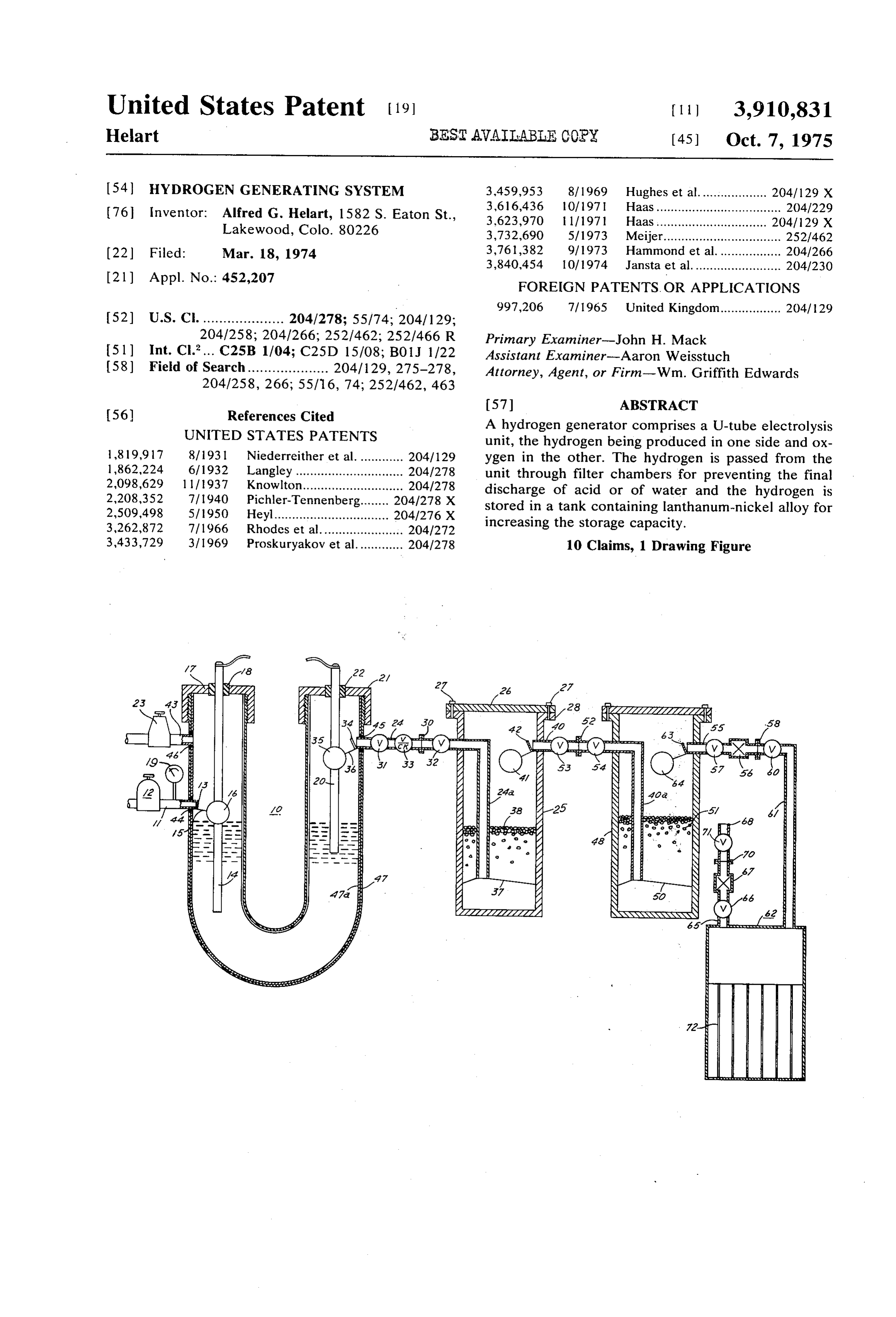
United States Patent (19) 11 3,910,831 Heart BEST AWAIIABLE COPY (45 Oct. 7, 1975
54 HYDROGEN GENERATING SYSTEM 3.459,953 8/1969 Hughes et al................... 204/129 X 3,616,436 lO/1971 Haas................................... 204/229 76 Inventor: Alfred G. Helart, 1582 S. Eaton St., 3,623,970 1 1/1971 Haas..... ... 204/129 X Lakewood, Colo. 80226 3,732,690 5/1973 Meijer................................. 252/462 3,761.382 9/1973 Hammond et al.................. 204/266 22 Filed: Mar. 18, 1974 3,840,454 10/1974 Jansta et al......................... 204/230 (21) Appl. No.: 452,207 FOREIGN PATENTS OR APPLICATIONS
204/258; 204/266; 252/462; 252/466 R Primary Examiner-John H. Mack 51) Int. C.?... C25B 1/04; C25D 15/08; B01J 1/22 Assistant Examiner-Aaron Weisstuch (58) Field of Search.................... 204/129, 275-278, Attorney, Agent, or Firm-Wm. Griffith Edwards
56) References Cited A hydrogen generator comprises a U-tube electrolysis UNITED STATES PATENTS unit, the hydrogen being produced in one side and ox 1819,917 8? 1931 Niederreither et al............. 204/129 ygen in the other. The hydrogen is passed from the 1862,224 6/1932 Langley .............................. 2041278 unit through filter chambers for preventing the final 2,098,629 1 11 1937 Knowlton - - - - - - - - - - - - - - - - - - - - - - - - - - - - 2041278 discharge of acid or of Water and the hydrogen is
cy. . . . . . . . . . . . . . . . . . . . . . . . 22. stored in a tankw containing lanthanum-nickel alloy for 3,262,872 7/1966 Rhodes et al....................... , increasing the storage capacity. 3,433,729 3/1969 Proskuryakov et al............. 2041278 10 Claims, 1 Drawing Figure
Page 2
Drawing sheet — no readable text.
Page 3
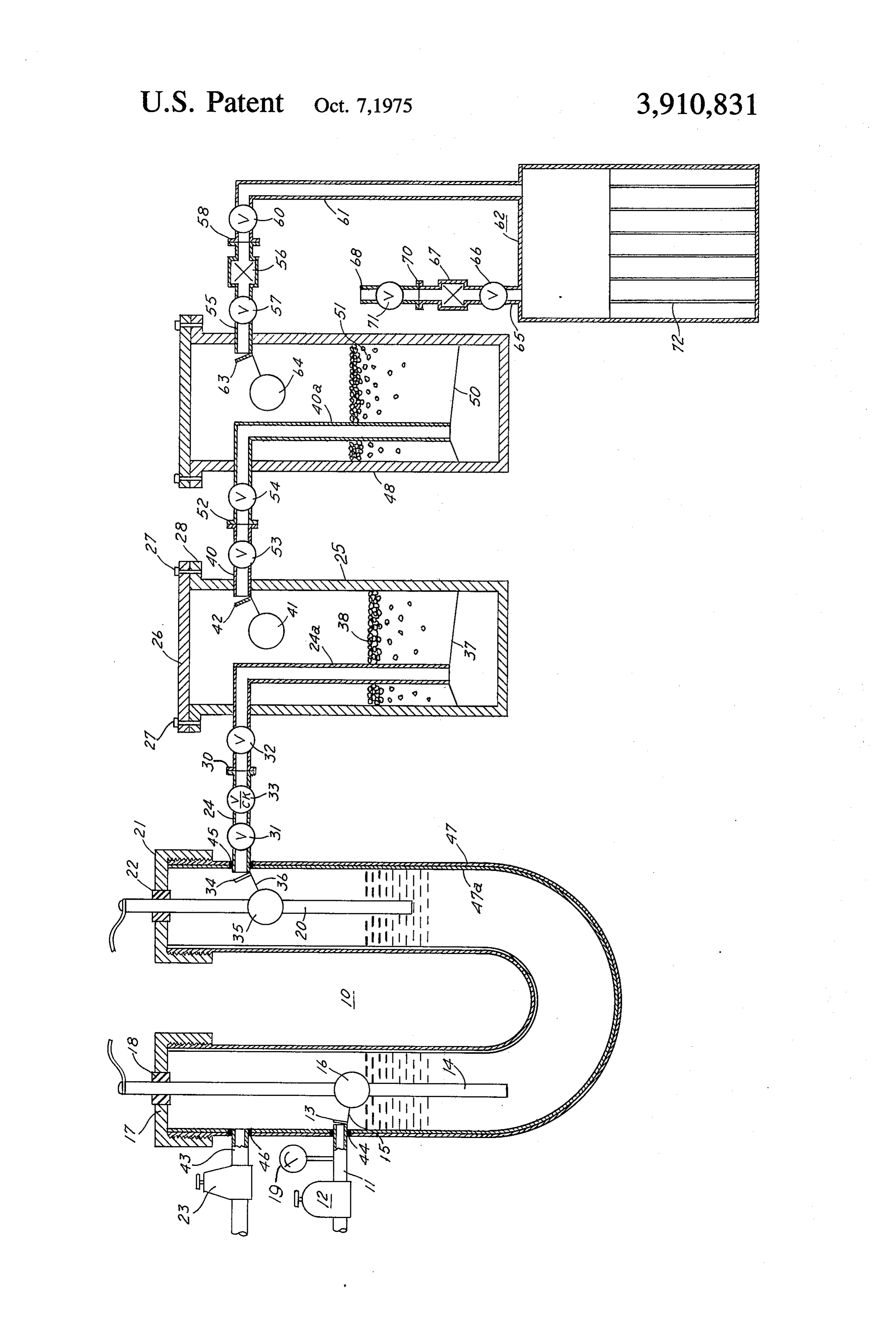
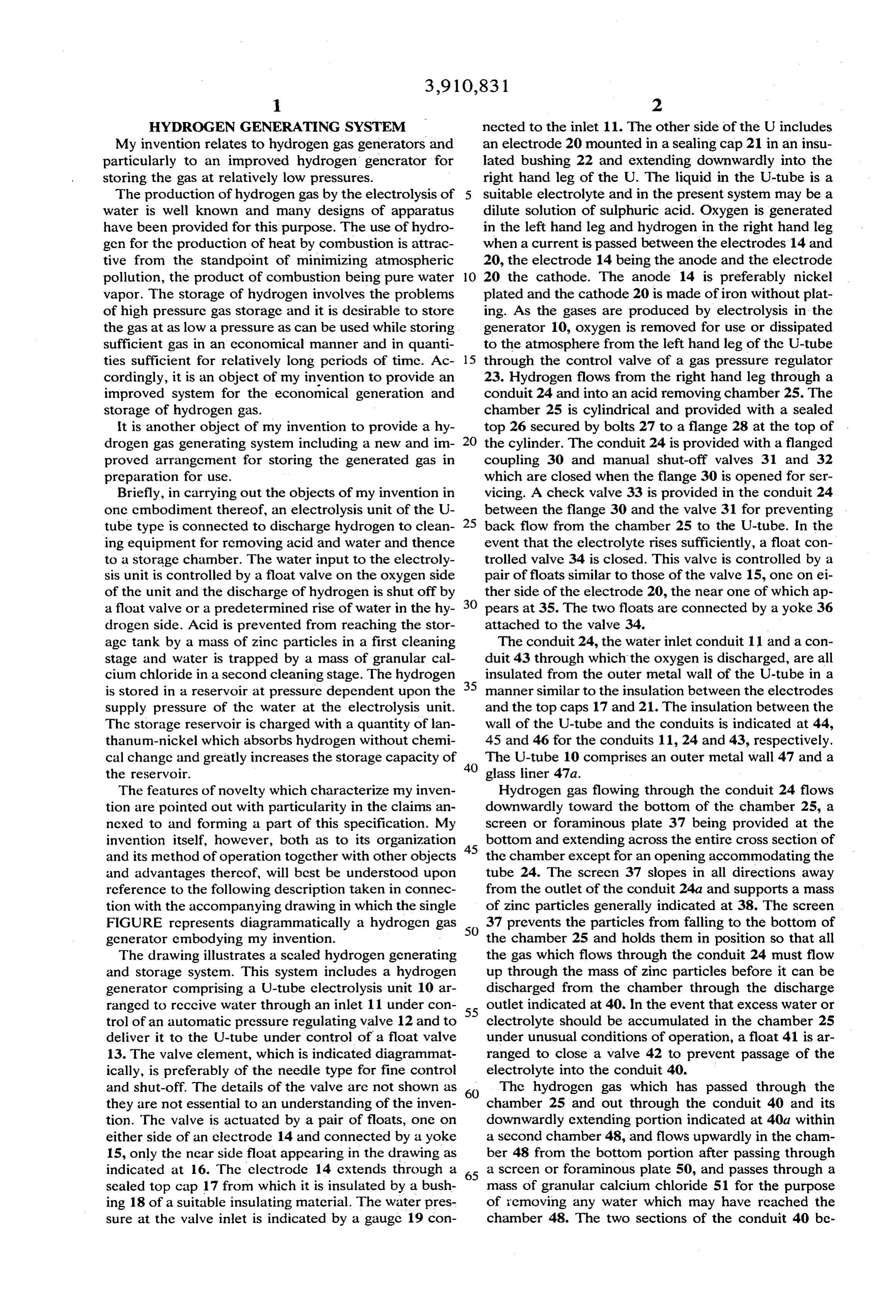
HYDROGEN GENERATING SYSTEM nected to the inlet 11. The other side of the U includes My invention relates to hydrogen gas generators and an electrode 20 mounted in a sealing cap 21 in an insu particularly to an improved hydrogen generator for lated bushing 22 and extending downwardly into the storing the gas at relatively low pressures. right hand leg of the U. The liquid in the U-tube is a The production of hydrogen gas by the electrolysis of suitable electrolyte and in the present system may be a water is well known and many designs of apparatus dilute solution of sulphuric acid. Oxygen is generated have been provided for this purpose. The use of hydro in the left hand leg and hydrogen in the right hand leg gen for the production of heat by combustion is attrac when a current is passed between the electrodes 14 and tive from the standpoint of minimizing atmospheric 20, the electrode 14 being the anode and the electrode pollution, the product of combustion being pure water O 20 the cathode. The anode 14 is preferably nickel vapor. The storage of hydrogen involves the problems plated and the cathode 20 is made of iron without plat of high pressure gas storage and it is desirable to store ing. As the gases are produced by electrolysis in the the gas at as low a pressure as can be used while storing generator 10, oxygen is removed for use or dissipated sufficient gas in an economical manner and in quanti to the atmosphere from the left hand leg of the U-tube ties sufficient for relatively long periods of time. Ac 15 through the control valve of a gas pressure regulator cordingly, it is an object of my invention to provide an 23. Hydrogen flows from the right hand leg through a improved system for the economical generation and conduit 24 and into an acid removing chamber 25. The storage of hydrogen gas. chamber 25 is cylindrical and provided with a sealed It is another object of my invention to provide a hy top 26 secured by bolts 27 to a flange 28 at the top of drogen gas generating system including a new and im the cylinder. The conduit 24 is provided with a flanged proved arrangement for storing the generated gas in coupling 30 and manual shut-off valves 31 and 32 preparation for use. which are closed when the flange 30 is opened for ser Briefly, in carrying out the objects of my invention in vicing. A check valve 33 is provided in the conduit 24 one embodiment thereof, an electrolysis unit of the U between the flange 30 and the valve 31 for preventing tube type is connected to discharge hydrogen to clean 25 back flow from the chamber 25 to the U-tube. In the ing equipment for removing acid and water and thence event that the electrolyte rises sufficiently, a float con to a storage chamber. The water input to the electroly trolled valve 34 is closed. This valve is controlled by a sis unit is controlled by a float valve on the oxygen side pair of floats similar to those of the valve 15, one on ei of the unit and the discharge of hydrogen is shut off by ther side of the electrode 20, the near one of which ap a float valve or a predetermined rise of water in the hy pears at 35. The two floats are connected by a yoke 36 drogen side. Acid is prevented from reaching the stor attached to the valve 34.
age tank by a mass of zinc particles in a first cleaning The conduit 24, the water inlet conduit 11 and a con stage and water is trapped by a mass of granular cal duit 43 through which the oxygen is discharged, are all cium chloride in a second cleaning stage. The hydrogen insulated from the outer metal wall of the U-tube in a is stored in a reservoir at pressure dependent upon the 35 manner similar to the insulation between the electrodes supply pressure of the water at the electrolysis unit. and the top caps 17 and 21. The insulation between the The storage reservoir is charged with a quantity of lan wall of the U-tube and the conduits is indicated at 44, thanum-nickel which absorbs hydrogen without chemi 45 and 46 for the conduits 11, 24 and 43, respectively. cal change and greatly increases the storage capacity of 40 The U-tube 10 comprises an outer metal wall 47 and a the reservoir. glass liner 47a.
The features of novelty which characterize my inven Hydrogen gas flowing through the conduit 24 flows tion are pointed out with particularity in the claims an downwardly toward the bottom of the chamber 25, a nexed to and forming a part of this specification. My screen or foraminous plate 37 being provided at the invention itself, however, both as to its organization 45 bottom and extending across the entire cross section of and its method of operation together with other objects the chamber except for an opening accommodating the and advantages thereof, will best be understood upon tube 24. The screen 37 slopes in all directions away reference to the following description taken in connec from the outlet of the conduit 24a and supports a mass tion with the accompanying drawing in which the single of zinc particles generally indicated at 38. The screen FIGURE represents diagrammatically a hydrogen gas 37 prevents the particles from falling to the bottom of generator embodying my invention. the chamber 25 and holds them in position so that all The drawing illustrates a sealed hydrogen generating the gas which flows through the conduit 24 must flow and storage system. This system includes a hydrogen up through the mass of zinc particles before it can be generator comprising a U-tube electrolysis unit 10 ar discharged from the chamber through the discharge ranged to receive water through an inlet 11 under con 55 outlet indicated at 40. In the event that excess water or trol of an automatic pressure regulating valve 12 and to electrolyte should be accumulated in the chamber 25 deliver it to the U-tube under control of a float valve under unusual conditions of operation, a float 41 is ar 13. The valve element, which is indicated diagrammat ranged to close a valve 42 to prevent passage of the ically, is preferably of the needle type for fine control electrolyte into the conduit 40. and shut-off. The details of the valve are not shown as 60 The hydrogen gas which has passed through the they are not essential to an understanding of the inven chamber 25 and out through the conduit 40 and its tion. The valve is actuated by a pair of floats, one on downwardly extending portion indicated at 4.0a within either side of an electrode 14 and connected by a yoke a second chamber 48, and flows upwardly in the cham 15, only the near side float appearing in the drawing as ber 48 from the bottom portion after passing through indicated at 16. The electrode 14 cxtends through a 65 a screen or foraminous plate 50, and passes through a sealed top cap 17 from which it is insulated by a bush mass of granular calcium chloride 51 for the purpose ing 18 of a suitable insulating material. The water pres of removing any water which may have reached the sure at the valve inlet is indicated by a gauge 19 con chamber 48. The two sections of the conduit 40 be
Page 4
tween the chambers 25 and 48 are joined by a detach electrode 20 and which disconnects the electric circuit able flanged coupling 52 and are provided with respec until the electrolyte again rises to contact the clec tive shut-off valves 53 and 54 for preventing the pas trode, whereupon the generation of hydrogen is re sage of gas in or out of the two chambers when the cou sumed.
pling is opened. The dry hydrogen gas passes out of the 5 The hydrogen generating system as disclosed has the chamber 48 through a conduit 55 having therein a filter advantage of providing a gas which is clean in that it 56 and a shut-off valve 57. This gas flows through a de burns without particulate residue, the product of com tachable flanged coupling 58 and a shut-off valve 60 bustion being pure water vapor. and thence downwardly through a conduit 61 to a stor The electricity for operation of the electrolysis gener age tank 62. A safety or emergency float valve compris ator may be supplied in any suitable manner and for ing a valve 63 and a float 64 is provided in the tank 48 many installations it is preferable to employ electrical to close the outlet in the event of flooding of the cham generating means which do not require the combustion ber 48. In the event of such emergency this prevents of ordinary fuels. Thus, water wheel generators, wind the admission of water to the storage tank 62. The stor mills and solar generators are suited for use in connec age tank 62 is provided with an outlet conduit 65 from 15 tion with this system. In all cases the electrolysis gener the top thereof and the conduit is provided with a shut ation may be continued during the operation of the off valve 66 and a filter 67. A supply conduit 68 for an water wheel, windmill or solar generator to store sub appliance or other utilization device employing hydro stantial amounts of hydrogen during the active period gen is connected to the conduit 65 by a flanged cou of the power means, the hydrogen being available over pling 70 and is provided with a manual shut-off valve extended periods due to the increased storage capabil 71. The pressure within the system as illustrated in the ity of the tank 62 when the generator is not in opera drawing is controlled by the pressure of the water en tion.
tering the electrolysis unit 10 through the inlet 11. The While I have illustrated a specific. preferred arrange system throughout is substantially at this pressure ex ment of my hydrogen gas generating system, other ap cept for differences in pressure due to the flow of the 25 plications and modifications will occur to those skilled hydrogen gas, and for differences in pressure due to the in the art. Therefore, I do not desire my invention to be water levels in the U-tube. The combined action of the limited to the details of the system illustrated and I in regulators 12 and 23 serves to control the pressure in tend by the appended claims to cover all modifications the system and maintain it within selected limits. For 30 which fall within the spirit and scope of my invention. example, with a water supply pressure at say fifty I claim:
pounds per square inch, the regulators may be set to 1. A hydrogen gas generating and storage system maintain a system pressure of the order of twenty-five comprising:
pounds per square inch for the generation and storage means utilizing the electrolysis of water for produc of hydrogen. The pressure maintained in the system 35 ing oxygen and hydrogen and including means pro may be somewhat variable over a selected relatively viding zones for collecting and for discharging the narrow range in the neighborhood of twenty-five two gases separately;
pounds per square inch during the operation of the sys means for supplying water to said producing means tem. and for maintaining a predetermined range of pres It is desirable to store large quantities of gas without 40 sures in said system;
requiring storage at high pressure and for this purpose a reservoir for storing the hydrogen gas at the pres I provide in the storage tank 62 a body of lanthanum sure maintained by said supplying means and con nickel alloy indicated at 72 and which is initially in the nected to the hydrogen zone of said producing form of rods or bars as supplied by the manufacturer. means;
At the present time this lanthanum-nickel alloy may be a body of lanthanum-nickel in said reservoir for rais purchased from Molybdenum Company of America, 45 ing the storage capacity thereof, and, White Plains, New York. Over the period of the opera means for withdrawing hydrogen from said reservoir tion of the system, lanthanum-nickel (LaNis) disinte for use.
grates from its bar form and forms a mass of powdered 2. A hydrogen gas generating and storage system as material in the lower portion of the tank 62. This mate set forth in claim including means connected between rial will last as a storage means over a long period of said producing means and said storage means for re time provided water and oxygen or other substances moving water from the hydrogen flowing to said stor capable of reacting with the alloy are prevented from age reservoir.
reaching it. The lanthanum-nickel alloy has the prop 3. A hydrogen gas generating and storage system as erty of absorbing large amounts of hydrogen and the 55 set forth in claim 1 including means for removing acid presence of the metal within the tank makes it possible from the hydrogen flowing toward said reservoir. to charge a substantially greater volume of gas within 4. A hydrogen gas generating and storage system as the tank, than can be charged in the tank at the same set forth in claim 1 including filtering and cleaning pressure without the metal present. As a result, sub means for removing foreign matter from the hydrogen stantial amounts of hydrogen gas may be stored within 60 and disposed in a hydrogen conduit between said pro the tank 62 for use as required by the utilization de ducing means and said reservoir means for supplying vices connected to the supply conduit 68. The electrol substantially pure hydrogen to said reservoir. ysis generator 10 may thus be run substantially continu 5. A hydrogen gas generating and storage system as ously over long periods of time subject to shut-down in set forth in claim 1 wherein said producing means is an the event of long periods of non-use of a stored gas. 65 electrolysis generator of the U-tube type wherein oxy The electrolysis operation is discontinued when the gas gen is generated in the water inlet leg of the U-tube and in the tank 62 reaches a predetermined pressure which hydrogen in the other leg thereof and including a first forces the electrolyte in the U-tube down below the float controlled valve for shutting the water supply on
Page 5
S 6 a predetermined rise of water in said inlet leg and a sec ing oxygen and hydrogen including means provid ond float controlled valve for closing the hydrogen out ing respective separate zones for collecting the let of said producing means upon a predetermined rise gases and means for discharging the separate gases; of water in said other leg. means for supplying water under pressure to said pro 6. A hydrogen gas generating and storage system as ducing means and utilizing the pressure of the set forth in claim 4 including two closed chambers con water for maintaining a predetermined range of nected in series in the hydrogen conduit between said pressures in said system; producing means and said reservoir, one of said cham a closed reservoir connected to the hydrogen zone of bers having means for retaining a mass of acid remov said producing means for receiving the discharged ing material therein and having means for directing the gas for storage at the pressure maintained by said flow of hydrogen from the lower portion upwardly supplying means;
through said mass, and the second of said chambers a body of metal alloy capable of absorbing large having a mass of dehydrating material therein and amounts of hydrogen gas at pressures of the order means for directing the hydrogen flowing therethrough of twenty-five pounds arranged in said reservoir for upwardly through said mass. 15 raising the storage capacity thereof, and, 7. A hydrogen gas generating and storage system as means for discharging hydrogen from said reservoir set forth in claim 1 including filter means connected in for use.
the discharge conduit of said reservoir for removing 10. A hydrogen gas generating and storage system as particulate matter from the hydrogen removed from set forth in claim 9 wherein said producing means is an said reservoir. electrolysis generator of the U-tube type wherein oxy 8. A hydrogen gas generating and storage system as gen is generated in the water inlet leg of the U-tube and set forth in claim 4 including detachable couplings in hydrogen in the other leg thereof and including a first the hydrogen conduit between said producing means float controlled valve for shutting the water supply on and said filtering and cleaning means and between said a predetermined rise of water in said inlet leg and a sec last mentioned means and said reservoir, and shut-off 25 ond float controlled valve for closing the hydrogen out valves on cach side of each of said couplings for pre let of said producing means upon a predetermined rise venting the loss of hydrogen to the atmosphere. of water in said other leg and wherein said separate 9. A hydrogen gas generating and storage system zones lie in the upper portions of respective ones of comprising: said legs.
means utilizing the electrolysis of water for produc k k k k ck
Provenance
- Collection
- Cited prior art
- Original PDF
- patentimages.storage.googleapis.com →
- Filed
- 1974-03-18
- Pages
- 5
- Method
- pdftotext (the PDF's own text layer) + pdftoppm 300dpi page scans
- Source
- Google Patents bibliographic record
- Granted
- 1975-10-07
- Inventors
- Alfred G Helart
- Transcribed from
- patentimages.storage.googleapis.com →