(T1) · also written as a run, T1a xxx T1n
Duty Cycle of Pulse Train
Also written Resonant Pulse-train
Where it is first named
Adjusting Pulse-train (210a xxx 210n) in such a way as to allow pulse off-time (T2) to be synchronized with collapsing and re-formation of electromagnetic field coupling across pulsing transformer (52/53) to produce unipolar pulse frequency (T1a xxx T1n), as illustrated in (220) of Figure (18) as to Figure (17).
How it is written
- (T1) 7×
- (T1a xxx T1n) 5×
- (T1/T2 - T3/T4) 2× with (T2) Duty Cycle of Pulse Train, (T3) Unipolar Pulse-Train, (T4) Trigger Pulse Frequency
- (T1/T4 - T3/T2) 1× with (T4) Trigger Pulse Frequency, (T3) Unipolar Pulse-Train, (T2) Duty Cycle of Pulse Train
- (T1 + T2a xxx T1 + T2n) 1× with (T2) Duty Cycle of Pulse Train
- (T1a xx T1n) 1×
- (T1 - T2a xxx T1 – T2n) 1× with (T2) Duty Cycle of Pulse Train
T1a xxx T1n is Meyer's shorthand for a run of the same thing: T1a is the first, T1n the last, and the x's stand for however many lie between. Every stage of the run is this one numeral.
Drawings 45
-
... causing "electron clustering" (641a xxx 641n) to take place within Copper Wire Zone (52) during pulse on- time (T1) · Electron Bounce Phenomenon
-
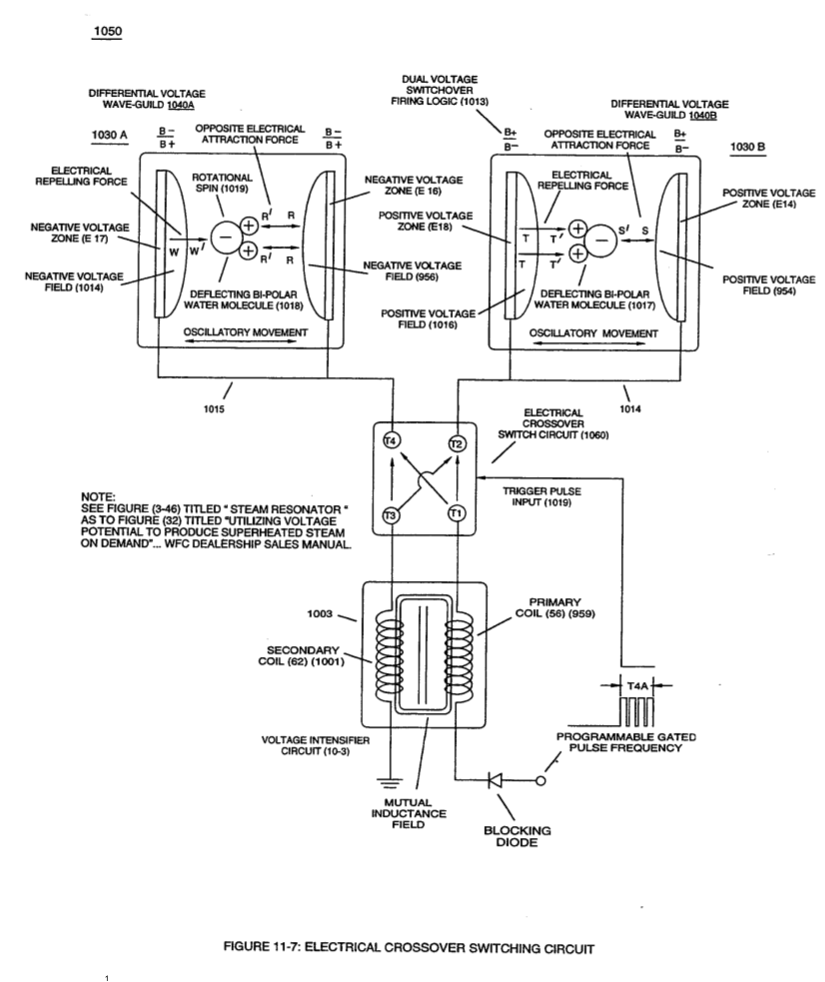
When (B+/B+ - B-/B- / 1030B) switch function is activated, switch terminals (T1/T2 - T3/T4) are closed. · Electrical Crossover Switching Circuit
-
(650) of Figure (7-4) · Amp Inhibiting Circuit Vs Voltage Enhancement
-
The figure it sits on · VIC Matrix Circuit
-
(628) of Figure (7-7) · Instant Explosion of Water
-
(T2) of Figure (7-8) · Instant Explosion of Water
-
(FI) of Figure (7-3b) · Instant Explosion of Water
-
Figure (7-8) · Resistance (Rs)
-
(650) of Figure (7-4) · Resistance (Rs)
-
(690) of Figure (7-8) · Resistance (Rs)
-
The figure it sits on · Inductance (FL)
-
(690) of Figure (7-8) · Inductance (FL)
-
(650) of Figure (7-4) · Inductance (FL)
-
Figure (7-3) · Inductance (FL)
-
(650) of Figure (7-4) · Capacitance (Cd)
-
(640) of Figure (7-3) · Capacitance (Cd)
-
(690) of Figure (7-8) · Capacitance (Cd)
-
(690) of Figure (7-8) · Inductance Reactance (Rs - Cd - FL)
-
(627) of Figure (7-7) · Inductance Reactance (Rs - Cd - FL)
-
Figure (7-8) · Inductance Reactance (Rs - Cd - FL)
-
Figure (7-3) · Multi-layer Coil
-
(690) of Figure (7-8) · Taper Resonant Capacitor (ERt)
-
"Voltage Deflection" of Figure (7-4) · Capacitance Reactance
-
690 of Figure 7-8 · Circuit Resistance
-
Inductance Charging Effect (660) of Figure (7-5) · Transformer Action
-
Distributed Capacitance (Cda xxx Cdn) of Figure (7-3) · Electron Bounce Phenomenon
-
Opposite Electrical Attraction Force (SS' ~ 617 ~ RR' - T3 - SS' ~ 617 - RR') of Figure (7-4) · Electron Bounce Phenomenon
-
(52) of Figure (7-8) · Electron Bounce Phenomenon
-
The figure it sits on · WFC 426 - Illustrations
-
The figure it sits on · WFC 426 - Illustrations
-
The figure it sits on · WFC 426 - Illustrations
-
The figure it sits on · WFC 426 - Illustrations
-
The figure it sits on · 8-2 - Traveling Voltage Wave-Guides
-
(690) of Figure (7-8) · 8-2 - Traveling Voltage Wave-Guides
-
(52) of Figure (7-8) · 8-3 - Electrical Voltage-Pulse Wave-Transmission
-
(Cp) of Figure (7-8) · 8-4 - State Space (Sp)
-
(650) of Figure (7-4) · 8-4 - State Space (Sp)
-
(690) of Figure (7-8) · 8-6 - VIC Voltage Sync-Pulse Circuit
-
(650) of Figure (7-4) · 8-6 - VIC Voltage Sync-Pulse Circuit
-
(Cp) of (7-8) · 8-6 - VIC Voltage Sync-Pulse Circuit
-
(690) of Figure (7-8) · Propagating Electrical Stress
-
"bifilar" wrapped coils (Figure 7-3) · Propagating Electrical Stress
-
The figure it sits on · Propagating Electrical Stress
-
The figure it sits on · WFC 429 - Illustrations
-
The figure it sits on · VIC Switchover Circuit
Where it is named · 18
Water Fuel Injector (Taper Resonant Cavity Chamber) 3×
-
Adjusting Pulse-train (210a xxx 210n) in such a way as to allow pulse off-time (T2) to be synchronized with collapsing and re-formation of electromagnetic field coupling across pulsing transformer (52/53) to produce unipolar pulse frequency (T1a xxx T1n), as illustrated in (220) of Figure (18) as to Figure (17).
-
Pulse on-time (T1) having a predetermined constant voltage level (xxx VL xxx) is adjusted to maximize transference of electromagnetic energy to Secondary Coil (53) during pulsing operations.
-
Resonant Pulse-train (T1 + T2a xxx T1 + T2n)
The resultant and newly formed gated Resonant Pulse-train (T1 + T2a xxx T1 + T2n) (58) voltage amplitude (Vo xxx Vn) is, now, attenuated by Sequential Voltage Amplitude Control Circuit (59) once step up Secondary Coil (53) produces a higher voltage level (xxxVL) above incoming pulse-train (210) since Secondary Coil (53) has a greater number of turns of wire.
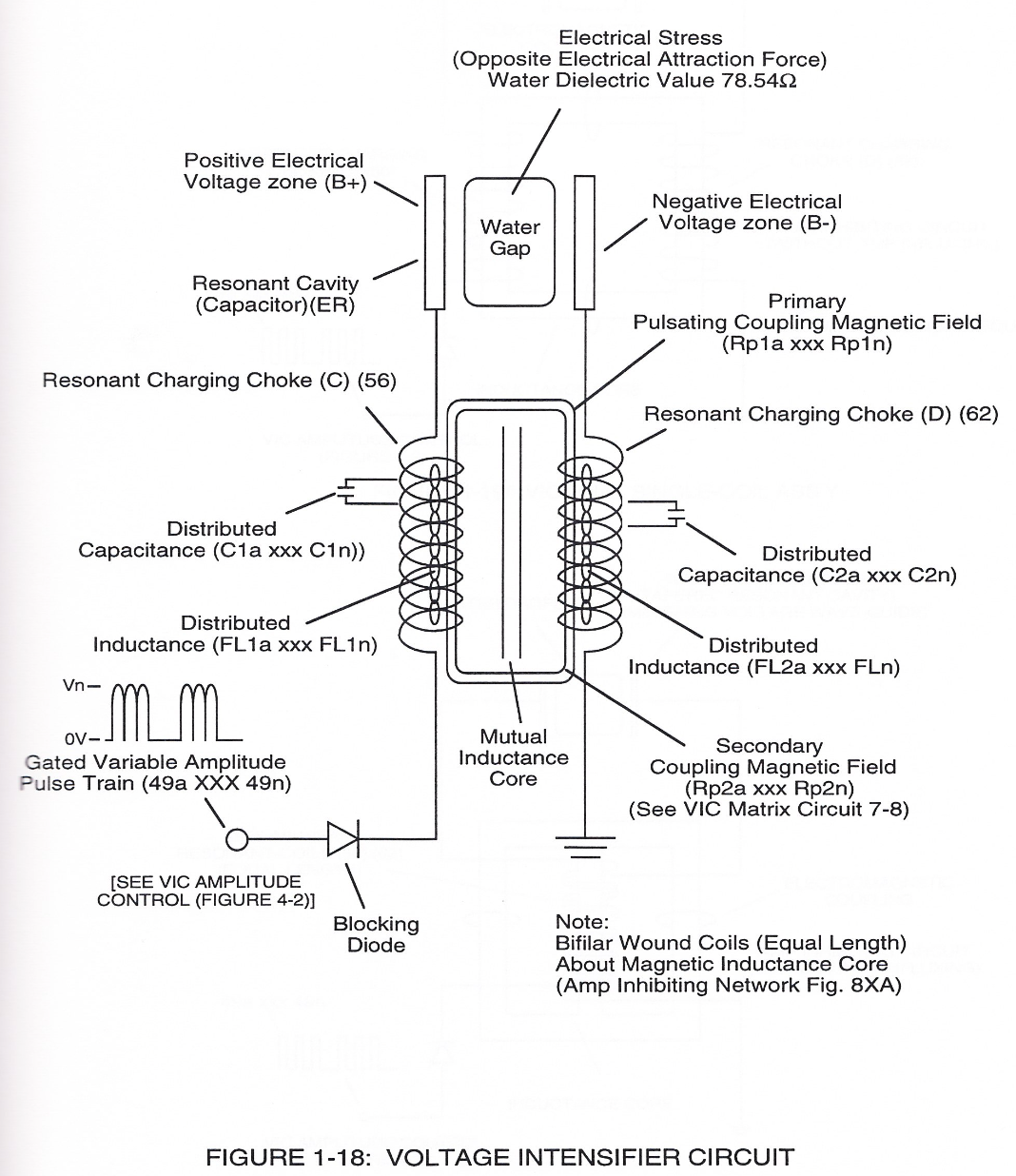
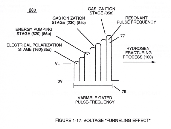
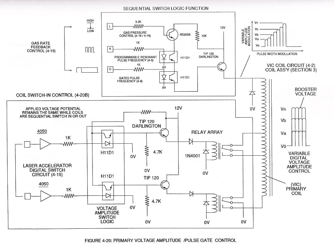
Instant Explosion of Water 1×
-
... producing unipolar voltage wave-form (64a xxx 64n) during repeated pulse-signal (46a xxx 46n) on-time (T1a xxx T1n)
Capacitance (Cd) 2×
-
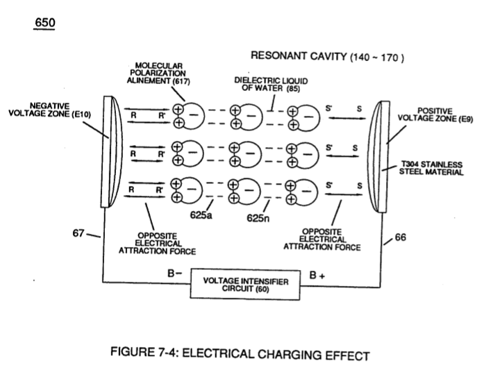
... which, after occurring, the newly formed molecular electrical orientation (625a xxx 625n) of Figure (7-4) remains in electrical atomic alignment after pulse off-time (T2) aiding the transference of voltage potential during pulse on-time (T1)
-
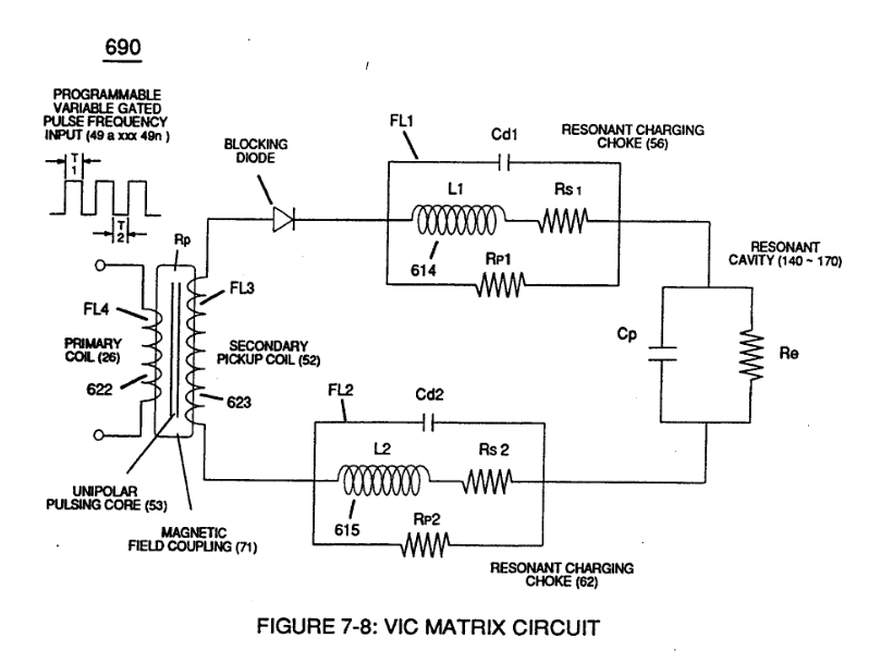
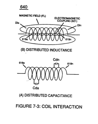
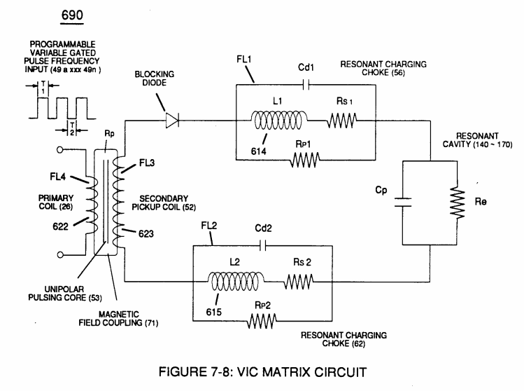
The circular-spiral turns of wire (forming parallel electrical surfaces) is separated by an Insulated Dielectric Coating Material which forms a series of capacitors (Cda xxx Cdn) when magnetic flux-lines (619a xxx 619n) produce Electromagnetic Coupling Field (621) during pulse on-time (T1), as illustrated in (640) of Figure (7-3) as to (690) of Figure (7-8).
Inductance Reactance (Rs - Cd - FL) 1×
-
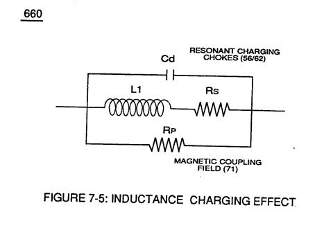
... overcoming any potential loss of pulse signal due to resistive interaction (Rsl/Rs2) of either or both Inductor Cores (L1/L2) wire-material to the formation of Inductance Fields (FL1/FL2) during reoccurring pulse on-time (T1a xxx T1n).
In-Line Circuit Components 2×
-
effectuates "Step Charging Effect" (680) of Figure (7-7) when Pulse off-time (T2) is less than Pulse on-time (T1)
-
Duty Cycle of Pulse Train (T1 - T2a xxx T1 – T2n)
Duty Cycle of Pulse Train (T1 - T2a xxx T1 – T2n)
Transformer Action 4×
-
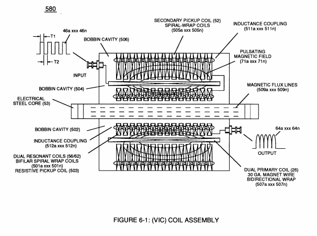
… currents that induce magnetic flux lines of forces (71a xxx 71n) emanating away from magnetic core material (53) and caused by Primary Coil (26) being electrically energized during pulsing operations (T1a xx T1n), as illustrated in (690) of Figure (7-8).
-
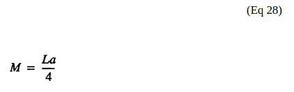
(1'2) is the sum of the magnetic field strength (FL4) of the primary coil (26) and the induced magnetic field (FL3) of the Secondary Pickup Coil (52) during each pulse cycle (T1) in direct relationship to repetitive pulse cycling (T1a xxx T1n) and both magnetic fields (FL3/FL4) interacting, and is expressed in the following equation:
-
(1'2) is the sum of the magnetic field strength (FL4) of the primary coil (26) and the induced magnetic field (FL3) of the Secondary Pickup Coil (52) during each pulse cycle (T1) in direct relationship to repetitive pulse cycling (T1a xxx T1n) and both magnetic fields (FL3/FL4) interacting, and is expressed in the following equation:
-
... thus, allowing Inductance Fields (FL1 - FL2 - FL3 - FL4) to be aiding one another during the same sequence of pulse-time (T1) ... …
Electron Bounce Phenomenon 2×
-
… orce (71a xx 71n) (Rp) emanating away from closed-loop magnetic pulsing core (53) of Figure (190) penetrates Inductance coil-windings (52 - 56 - 62) simultaneously during each and every pulse on-time (T1a xxx T1n) as programmable pulse-train (49a xxx 49n T3 - 49a xxx 49n) is adjusted to "Tune - in" to the dielectric property of Water (Re)
-
... causing "electron clustering" (641a xxx 641n) to take place within Copper Wire Zone (52) during pulse on- time (T1)
Electrical Crossover Switching Circuit 3×
-
When (B+/B+ - B-/B- / 1030B) switch function is activated, switch terminals (T1/T2 - T3/T4) are closed.
-
Switch position (T1/T4 - T3/T2) reverses voltage polarity once switch function (T1/T2 - T3/T4) goes to close position after Switch Logic Function (1013) becomes an open circuit
-
Switch position (T1/T4 - T3/T2) reverses voltage polarity once switch function (T1/T2 - T3/T4) goes to close position after Switch Logic Function (1013) becomes an open circuit