(220)
Voltage Dynamics
Also written Voltage Intensifier Circuit
Where it is first named
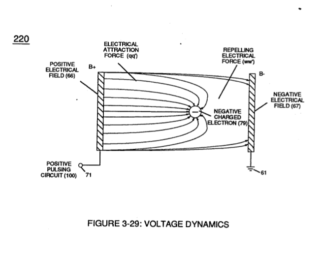
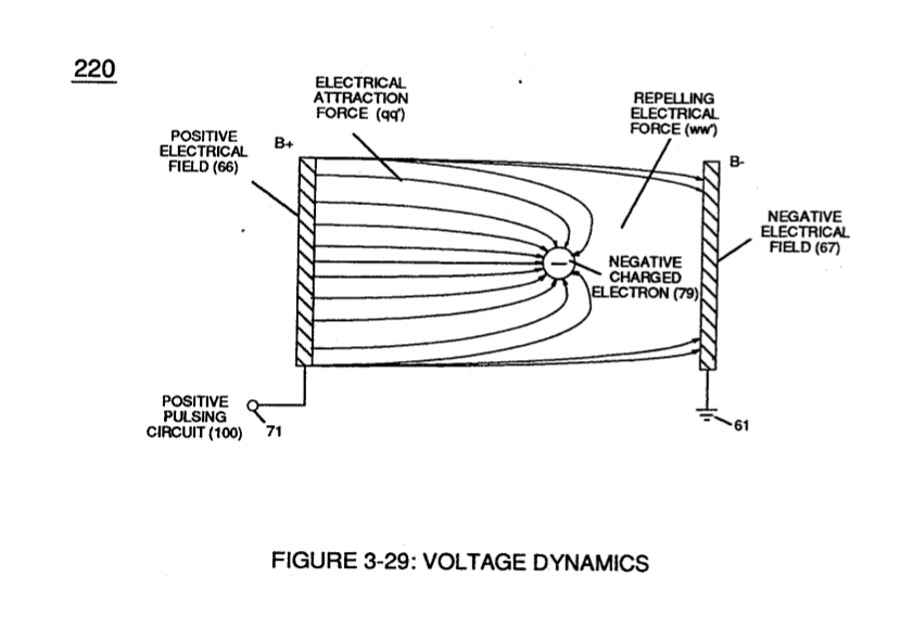
Ions or particle mass having the same or like electrical charges will move away from one another, as illustrated in (220) of Figure (3-29).
How it is written
- (220) 14×
Drawings 15
-
In both cases, electrical charge deflection or movement is directly related to applied voltage (65). · Voltage Dynamics
-
Ions or particle mass having the same or like electrical charges will move away from one another, as illustrated in (220) of Figure (3-29). · Voltage Dynamics
-
Figure (3-29) · Electrically Charged Water Molecule
-
Carries this number · WFC 422DA - Illustrations
-
Carries this number · Electronic Circuit Design
-
Carries this number · Electronic Circuit Design
-
Carries this number · Electronic Circuit Design
-
Carries this number · Electronic Circuit Design
-
Carries this number · Electronic Circuit Design
-
(220) of Figure (18) · Water Fuel Injector (Taper Resonant Cavity Chamber)
-
thereby, attenuating voltage amplitude (voltage intensity) beyond Secondary Coil (53) voltage levels (71), as illustrated in (220) of Figure (18). · Funneling Effect
-
Carries this number · Steam Resonator Assembly
-
Voltage Dynamics (220) of Figure (3-29) · Electron Bounce Phenomenon
-
Voltage Dynamics (220) of Figure (3-29) · WFC Exhaust Air Reclaimer
-
Figure (4-4) · Water Fuel Injection System - Page 1
Where it is named · 14
Voltage Dynamics 1×
-
Ions or particle mass having the same or like electrical charges will move away from one another, as illustrated in (220) of Figure (3-29).
Water Fuel Injector (Taper Resonant Cavity Chamber) 7×
-
Voltage Intensifier Circuit (220)
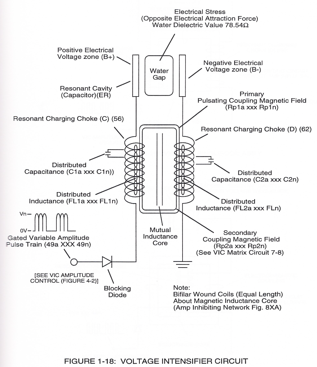
Voltage Intensifier Circuit (220) of Figure (18) allows Electrical-Stress variation (SS' = RR' / TT' = UU') since voltage Intensifier Circuit (220) inhibits electron-flow (amp restriction) into voltage triggering process (210) of Figure (17) as to (100) of Figure (6).
-
voltage Intensifier Circuit (220)
Voltage Intensifier Circuit (220) of Figure (18) allows Electrical-Stress variation (SS' = RR' / TT' = UU') since voltage Intensifier Circuit (220) inhibits electron-flow (amp restriction) into voltage triggering process (210) of Figure (17) as to (100) of Figure (6).
-
Incoming pulse-train (210a xxx 210n) is adjusted to "tune-in" to the Dielectric Properties of Water (47) which allows Resonant Action (see WFC Memo 424, once again) to occur since the Dielectric property of water (78.54 value) becomes a integral part of Electronic Circuit (110) of Figure (7) as to (220) of Figure (18)
-
(220) of Figure (18)
-
... forming a capacitor (E7 / E8) in series with Resonant Charging Chokes (56/57) placed on opposite sides of Resonant Cavity Zone (35) as to Figure (7) and (8) . . . forming a Resonant Pulsing Circuit (110) of Figure (7) with step-up Pulsing Transformer (33/36), as shown in (220) of Figure (18).
-
Adjusting Pulse-train (210a xxx 210n) in such a way as to allow pulse off-time (T2) to be synchronized with collapsing and re-formation of electromagnetic field coupling across pulsing transformer (52/53) to produce unipolar pulse frequency (T1a xxx T1n), as illustrated in (220) of Figure (18) as to Figure (17).
-
(220) of Figure (18)
Funneling Effect 2×
-
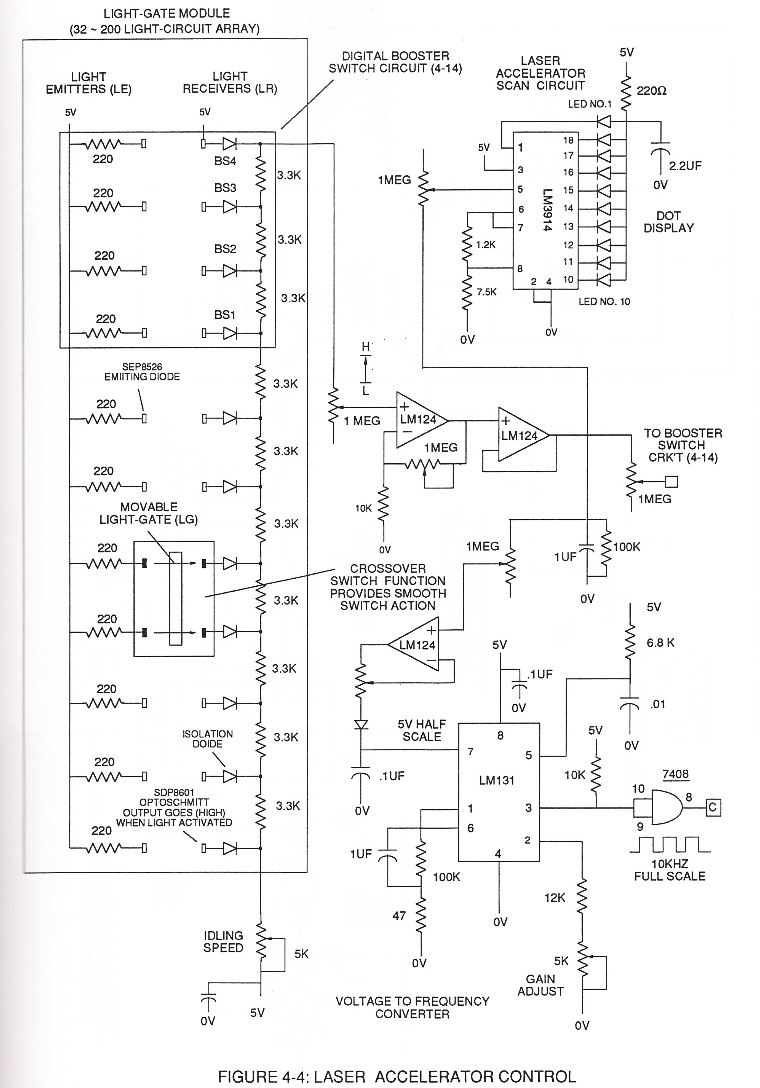
thereby establishing Voltage Level Logic Function (260) which is electronically transferable in sequential order (260a xxx 260n) by Laser Acceleration Control Circuit (4-4) of (220) of Figure (18).
-
thereby, attenuating voltage amplitude (voltage intensity) beyond Secondary Coil (53) voltage levels (71), as illustrated in (220) of Figure (18).
Electron Bounce Phenomenon 2×
-
Voltage Dynamics (220)
... setting up and performing pulsating Opposite Electrical Attraction Force (SS' ~ 617 ~ RR' - T3 - SS' ~ 617 - RR') of Figure (7-4) as to Voltage Dynamics (220) of Figure (3-29)
WFC Exhaust Air Reclaimer 2×
-
Voltage Dynamics (220)
... pulling apart and separating the atoms of the Nitric Oxide NO molecule by way of Voltage Dynamics (220) of Figure (3-29) under the law of physics which states "opposite electrical charges attracts", as so illustrated in (900) of Figure (9-1).